One of the most common problem with the Amiga 4000 is for sure Battery leakage.
This post will be about repairing such stuff and will be updated.
If you get an Amiga. first thing you should do is remove the battery. The machine runs just fine without it and most can live without it. the only thing it does is to keep time and date when the machine is turned off. IF you decide to use a battery, please solder wieres and place the battery somewhere else FAR AWAY from the motherboard. (there are space in the front) or install a coin-cell battery, but you have to add a diode so the machine does not try to charge that battery. more about that later hopefully.
Well, many times you are too late and have a machine that stopped to work due to leakage.
First, remove the battery and clean up. I usually add concentraded lemonjuice first (YUP! you read it all right) this will start a reacion and it will fizz for a while.
When the reacion is done, clean the board GOOD with isopropanol (99% clean atleast) and toothbrush. this might often actually damage weak traces. but have to be done.
If you want to do it really good, I recomend to unsolder and out back new ICs around aswell. as base from the battery (no, not acid) could have come under the ICs and slowly still kill it.
Then the hard job starts, to check for bad traces. here I will put a list of traces to check.
Many times you will end up in a nonbooting machine, mouse works bad or no fastmem.
so first for Mouseproblems and no boot:
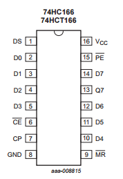
U975 and U976 is a 74HCT166 with pinout:
So where is those pins connected: well simply:
U975:
1 – U976 Pin 13
2 – R981 -> +5V
3 – R982 -> +5V
4 – R983 -> +5V
5 – R984 -> +5V
6 – U976 Pin 6
7 – U976 Pin 7
8 – GND
9 – U976 Pin 9
10 – R985 -> +5V
11 – R986 -> +5V
12 – R987 -> +5V
13 – U450 Pin 20 (MDAT) (IF this line is low machine will not boot!)
14 – R988 -> +5V
15 – U976 Pin 15
15 – +5V (C975)
U976:
If you notice that you only have ECS screenmodes in WB. this is the problem. usually GND is corroded meaning this is not working atall.. then you will loose AGA screenmodes in WB.
(in games and demos it will work!)
1 – R975 -> GND
2 – GND
3 – GND
4 – R993 -> +5V (J975 Pin 1)
5 – R994 -> +5V (J975 Pin 3)
6 – U975 Pin 6 -> CN200 Pin 3 (Pin 10 of U131) (DISABLE)
7 – U975 Pin 7 -> R500 -> U450 Pin 22 (SCLK)
8 – GND
9 – U975 Pin 9 -> U140 Pin 6 (_IORST)
10 – R992 -> +5V (J975 Pin 5)
11 – R991 -> +5V (J975 Pin 7)
12 – R990 -> +5V (J975 Pin 9)
13 – U975 Pin 1
14 – R989 -> +5V (J975 Pin 11)
15 – U975 Pin 15 -> U450 Pin 21 (_MLD)
16 – +5V (C976)
U177
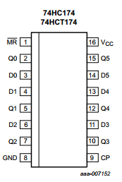
This is a 74HCT174 With pinout: A badly damaged U177 can be a root of “green screen of death” problems. remove it and it should work. (then replace..if you want RTC..)
1 – R182 -> +5V
2 – RP176 Pin 5 -> U178 Pin 7
3 – A(31:5)
4 – A(31:4)
5 – RP176 Pin 4 -> U178 Pin 6
6 – A(31:3)
7 – RP176 Pin 3 -> U178 Pin 5
8 – GND
9 – U354 Pin 9 (also a via under U198 close to Pin 1)
10 – RP178 Pin 2 -> U176 Pin 4
11 – A(31:2)
12 – Not Connected
13 – Not Connected
14 – Not Connected
15 – Not Connected
16 – +5C (C177)
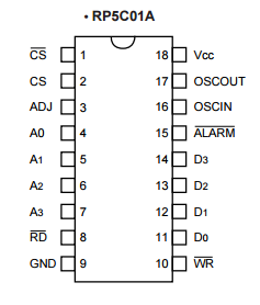
And the RTC Chip U178, an RP5C01 With pinout:
1 – R181 -> GND
2 – PWR GOOD (CN160 Pin 1)
3 – GND
4 – U177 Pin 10
5 – U177 Pin 7
6 – U177 Pin 5
7 – U177 Pin 2
8 – RP176 Pin 7 -> U150 Pin 52 (_RTCR)
9 – GND (C200)
10 – RP176 Pin 6 -> U150 Pin 50 (_RTCW)
11 – U175 Pin 16
12 – U175 Pin 17
13 – U175 Pin 18
14 – U175 Pin 19
15 – RP176 Pin 8 (_ALARM)
16 – Y176 Pin 1 -> VC190
17 – Y176 Pin 2 -> C179
18 – C200
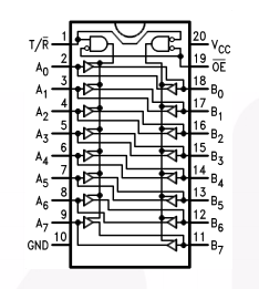
And finally we have U891 that handles the lower 8 bits of the fastmem and usually are affected, leaving the machine without fastmem, or a red screen
This is a 74F245 with Pinout:
1 – U130 Pin 6 (BR_W)
2 – U853 Pin 2 (SIMM Bit 0)
3 – U853 Pin 4 (SIMM Bit 1)
4 – U854 Pin 6 (SIMM Bit 2)
5 – U854 Pin 8 (SIMM Bit 3)
6 – U854 Pin 20 (SIMM Bit 4)
7 – U854 Pin 22 (SIMM Bit 5)
8 – U854 Pin 24 (SIMM Bit 6)
9 – U854 Pin 26 (SIMM Bit 7)
10 – GND
11 – R8 – U250 Pin 78
12 – R7 – U250 Pin 79
13 – R6 – U250 Pin 81
14 – R5 – U250 Pin 82
15 – R4 – U250 Pin 83
16 – R3 – U250 Pin 84
17 – R2 – U250 Pin 85
18 – R1 – U250 Pin 86
19 – U894 Pin 19
20 – +5V (C891)
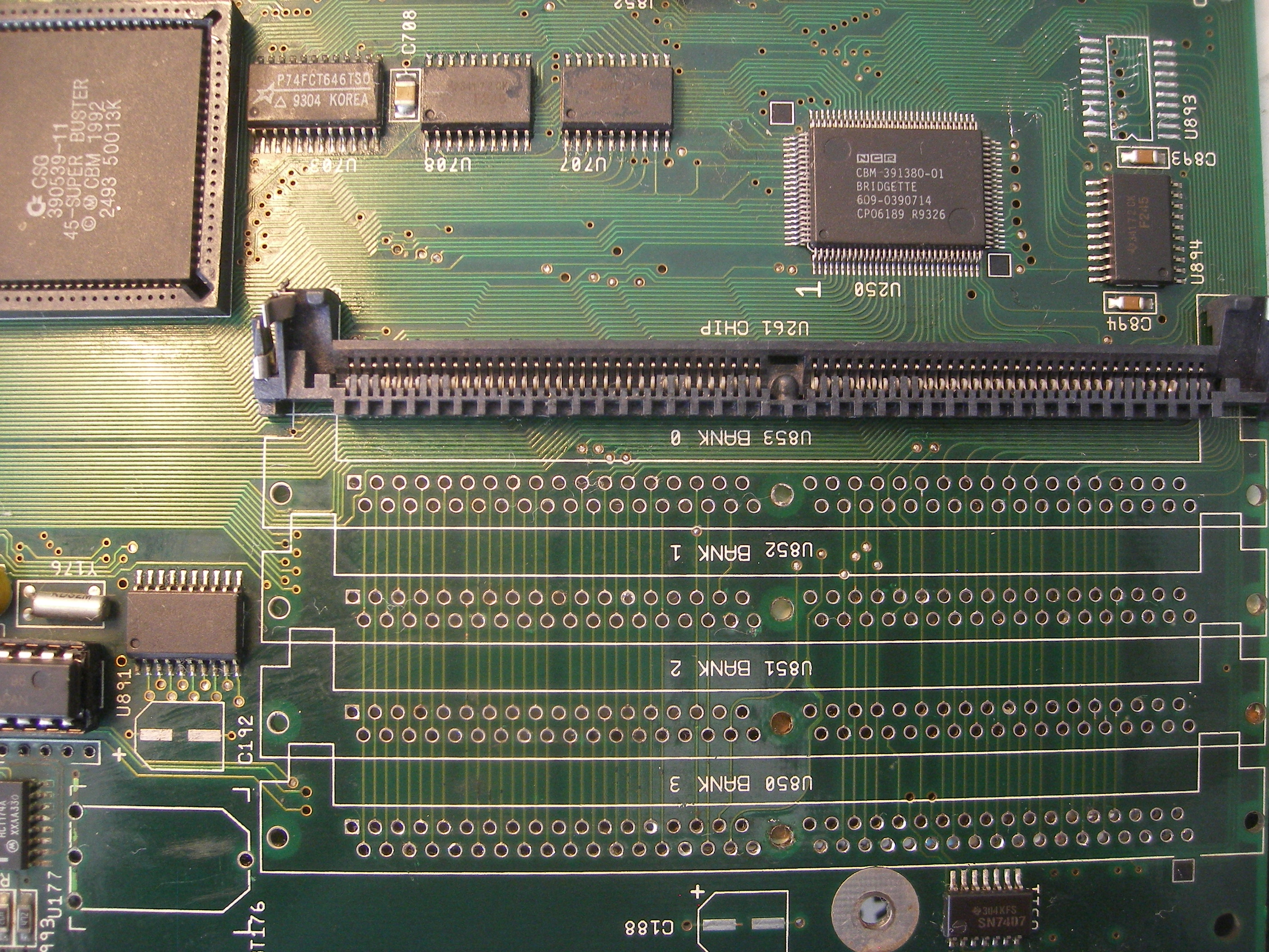
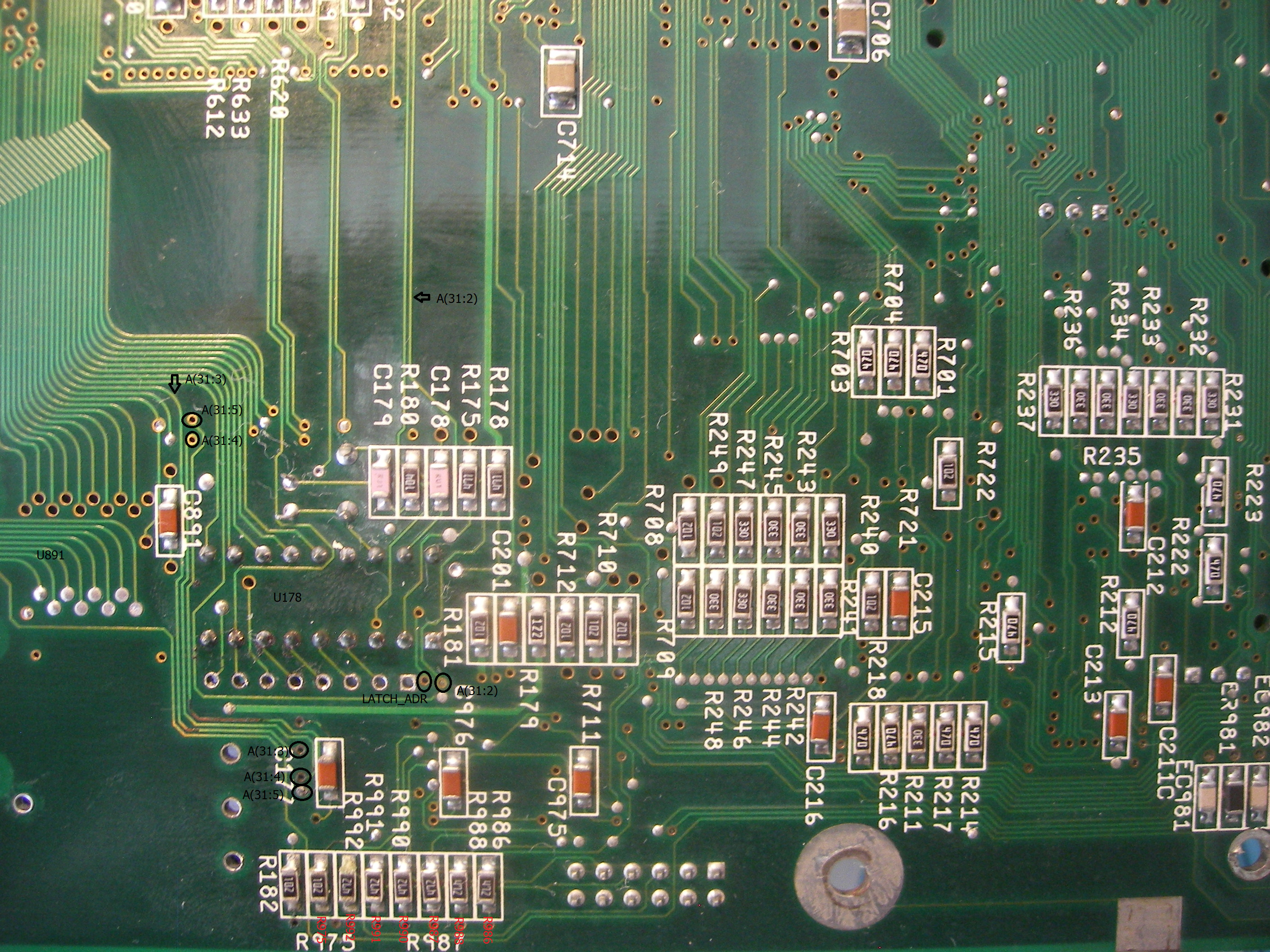
Here are pictures of the motherboard with some signals marked, and SIMM sockets removed:
TOP Side:

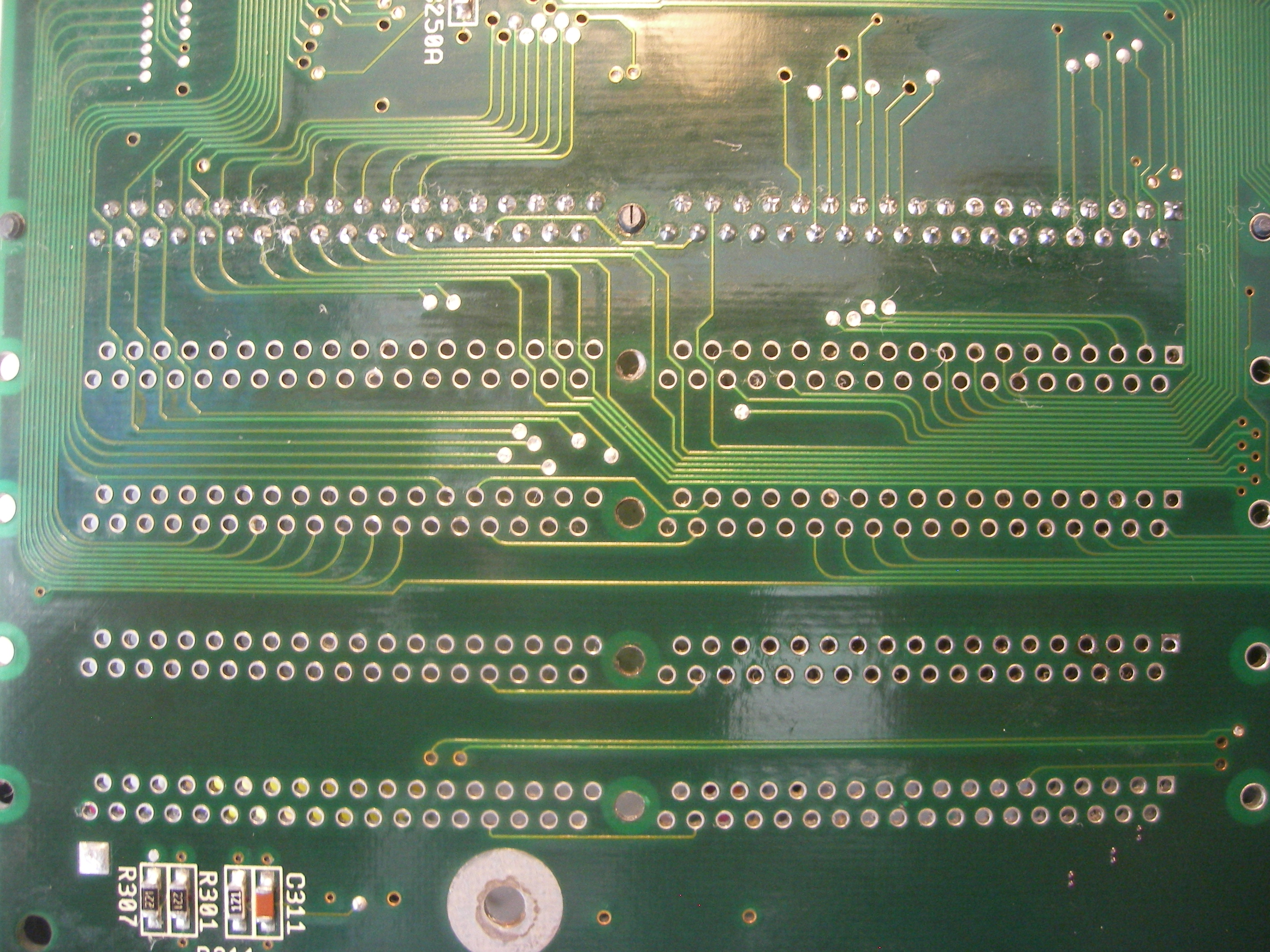
BOTTOM Side:
Oh boy.. you save my life with the memory workaround.. another a4k back to life
Always great to read
Hello, the capacitor c 192 is connected on which ic?
I recomend you to have a look at:
Hello,
after fixing battery damage I am greeted with yellow screen on kickstart, diagrom is showing errors in fast ram.
keyboard / mouse is sluggish with diagrom (on cn975, left button works, cn976 only right, keyboard is reacting slowly, have to press keys for a few 100ms to react.
I swapped following chips to a working unit and think they are not cause of the problem:
CPU Card
Chip Ram
Fast Ram
Fat Buster
CIA A + B
LISA
ALICE
BRIDGETTE
ROM HI + LO
RAMSEY
Due to battery damage I replaced:
U891
U178
U177
U976
U975
Do you have any idea what to check next? scope is available so I’m very eager to learn 🙂
best regards and thank you so much for diagrom it’s helping the community a LOT.
best
Are you sure your memory is ok?
Mr Hertell, Where can I find the A3000 motherboard schematic as seen on Youtube “Chris Edwards E115 Amiga 3000 restoration 3” I am in the process of repairing an A3000 with battery damage.