OK Next part..
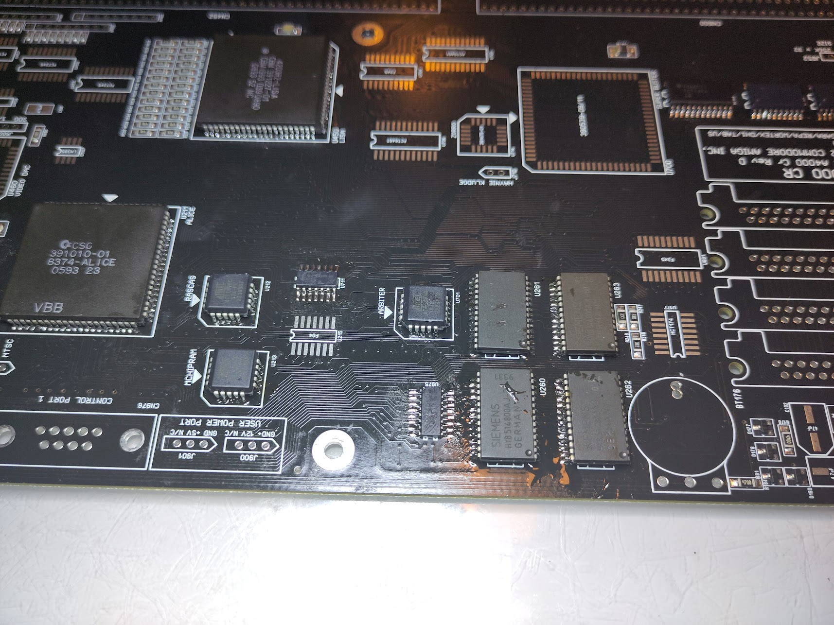
Time to get Chipmem working. and this is one of the bigger changes Commodore did on the CR. they added chipmem onboard.
so add:
U212, U213 (16V8) (those are NOT compatible from the GALs from the Rev2 A4000)
U260, U261, U262, U263 (memory)
Now Chipmem will work.
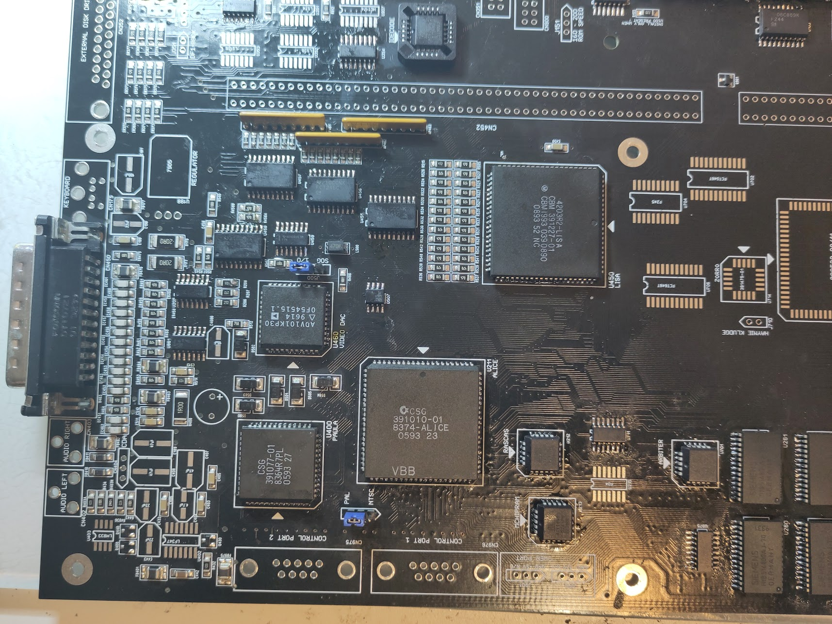
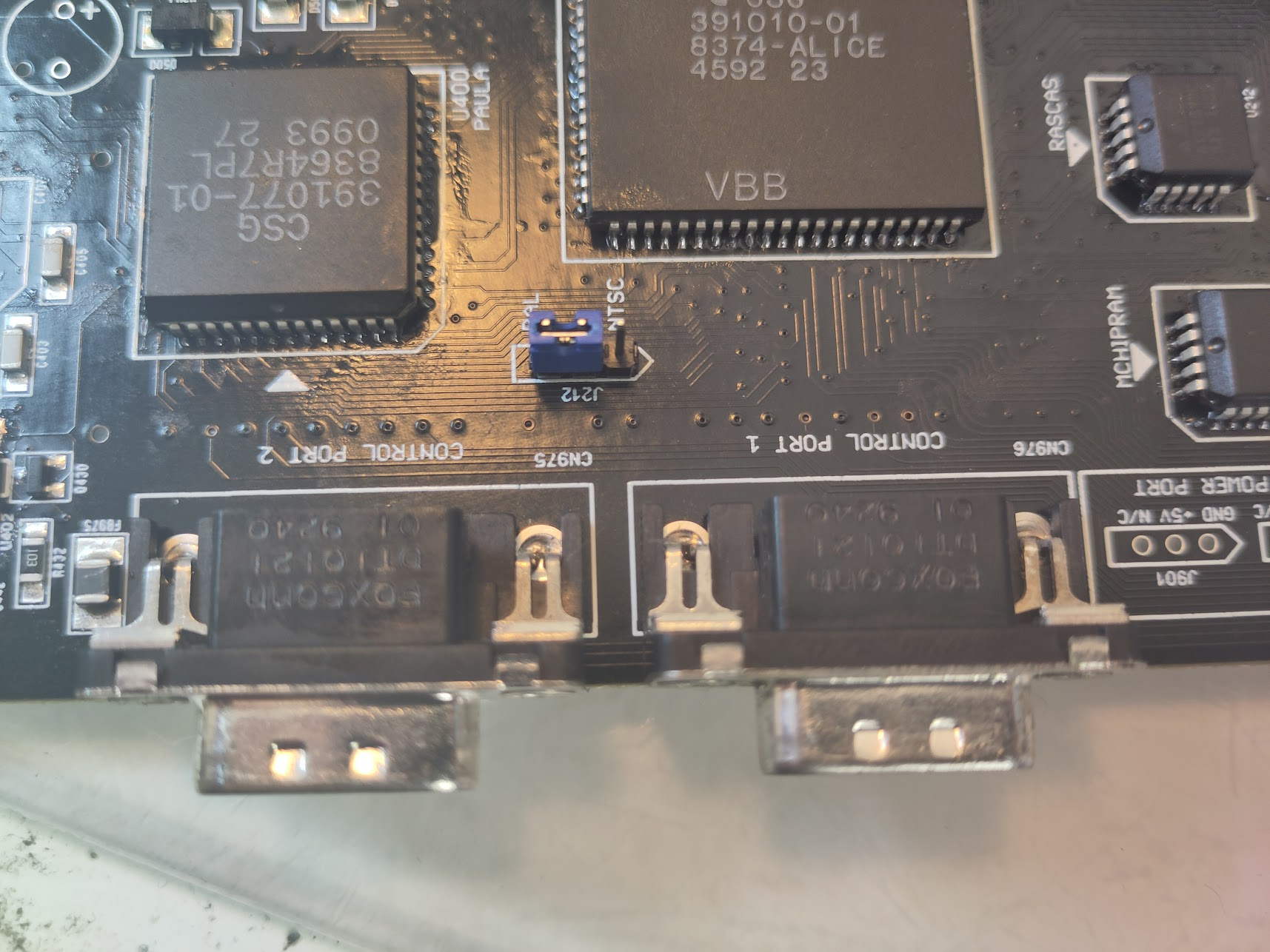
Time to get something “on screen”
U205 (74HC4066)
U455, U456, U457, U458 (74FCT245)
U459 (74F74)
D507 (LM385 1.2)
RP461, RP462, RP463 (1K 9Pin Bussed)
Header: J500, Jumper to pin 1-2
Header: J212 Jumper to PAL or NTSC
U460 BT101 (NOTE!!! THIS IS NOT THE SAME AS ON A4000 REV 2/B, also have a different rotation then A4000)
Nice. So.. some Fastmem is always nice.
Add:
For the moment we do it for 16MB Ram! so R818, R819 should be 0 Ohm resistors and let R820, R821 EMPTY!
U891, U892, U893, U894 (74F245)
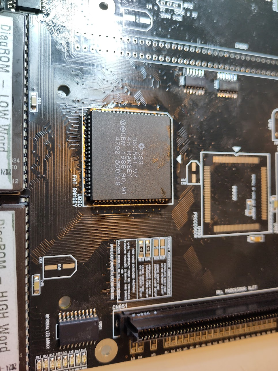
Add Ramsey
Add Jumper J852, Set to 1-2 for 16MB. (or 64MB later)
Add simmsockets. if you notice I only populate BANK1 and BANK3 this is due to I use 8MB simms. it is a undocumented feature of the A4000 and as I have LOTS of 8MB simms I populate only those 2. if you want to use 4MB simms. populate all.
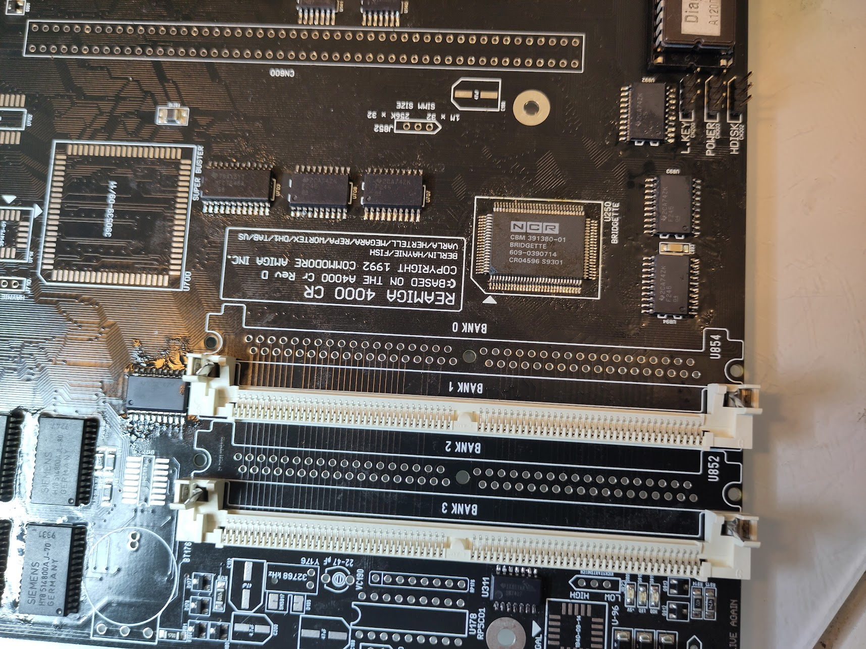
We do the talk about the 64MB Feature later.
Time to add more stuff..
Paralellport.
Add the Paralellport and CIA U300
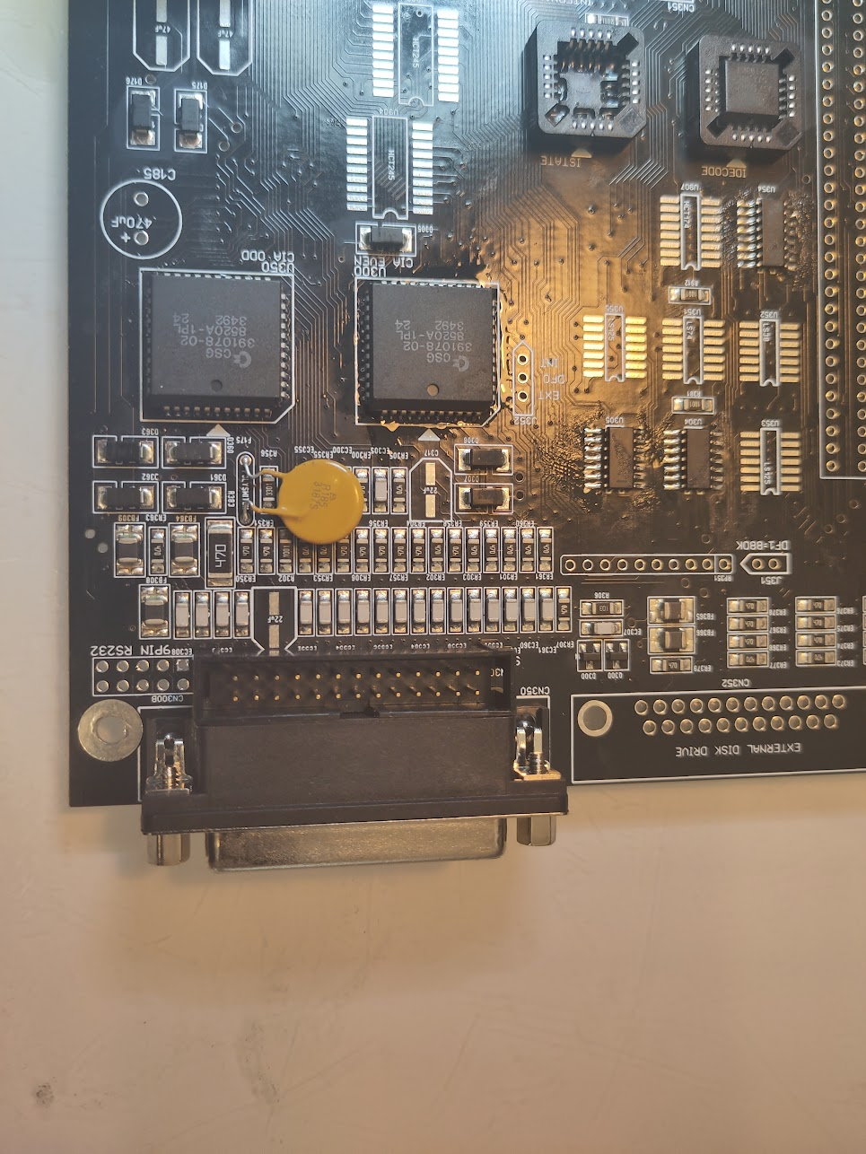
So some Floppytime. (even if this is something I never use. do not even OWN one. but)
Add
U353, U355 (74LS125A)
U351 (74LS74)
U352 (74LS38)
External Floppy Connector
Floppy Connector
RP351 (1k, 10Pin Bussed)
J351
J352 (Jumper on 1-2)
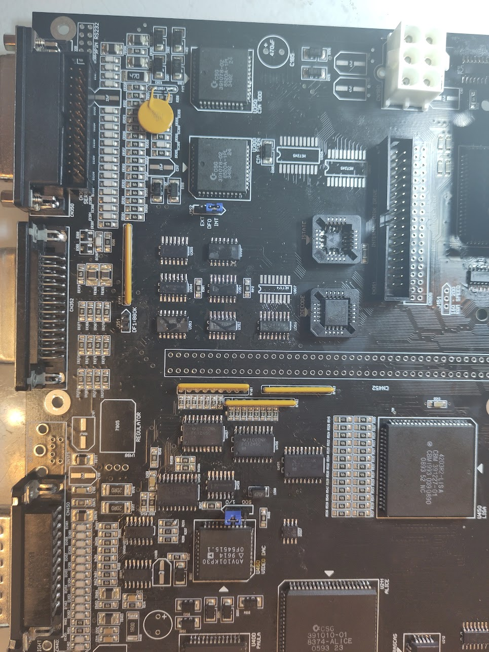
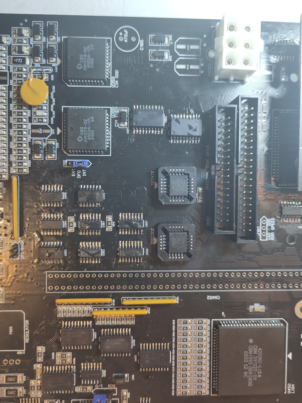
Time for something more useful. IDE.
Add
U902 (16V8)
U907 (74HCT174)
U903, U904 (74HCT245)
IDE Connector.
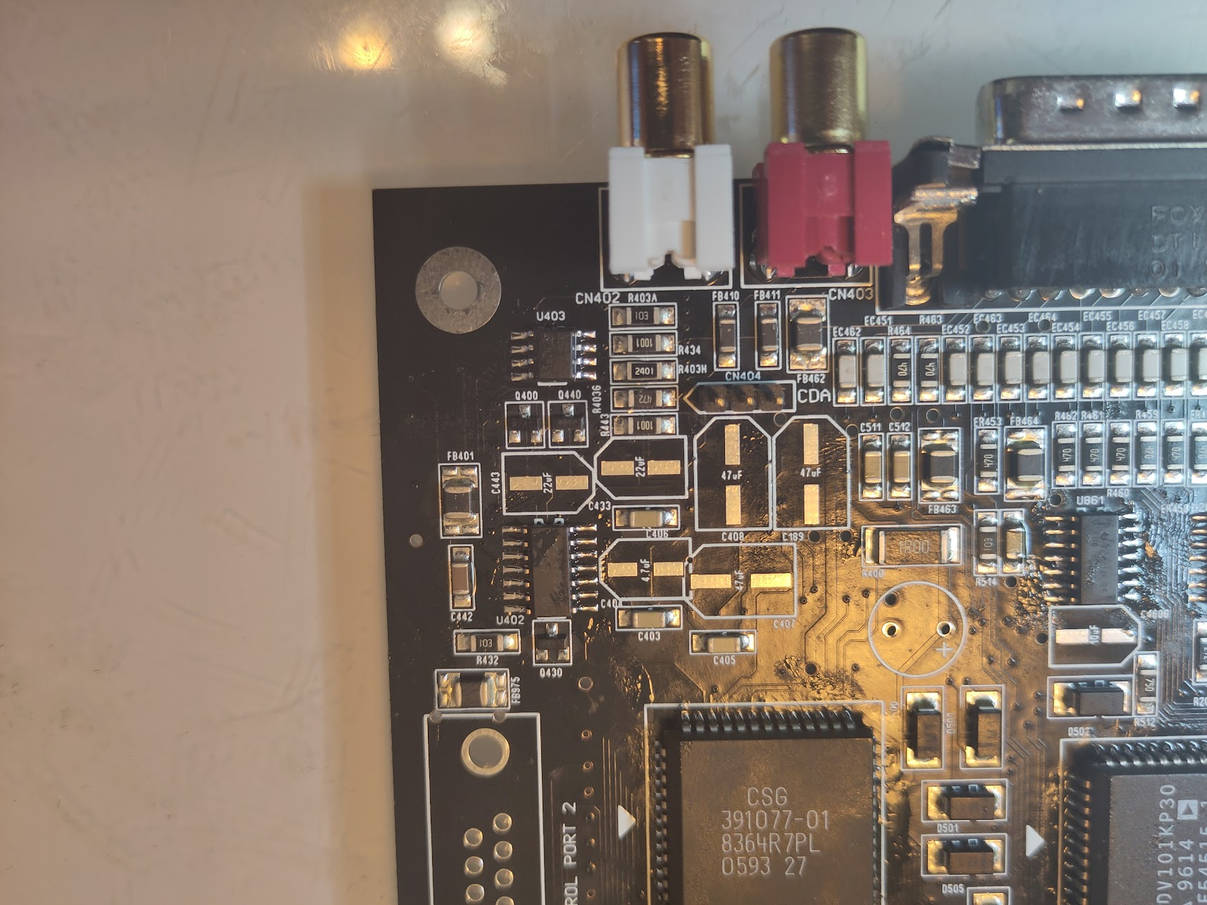
The Amiga is known for its Audio.. soo.. AUDIO!?
Add:
U402 (LF347)
U403 (LM833)
Header CN404
RCA Ports
And you will have a working audio! BUT if you test now you will not hear anything. but if you short pins on C443 or C433 you will hear sound. I add the capacitors later!
We need to add some extra stuff:
U215 (74F04)
U702, U706 (74FCT646)
U704 (74F245)
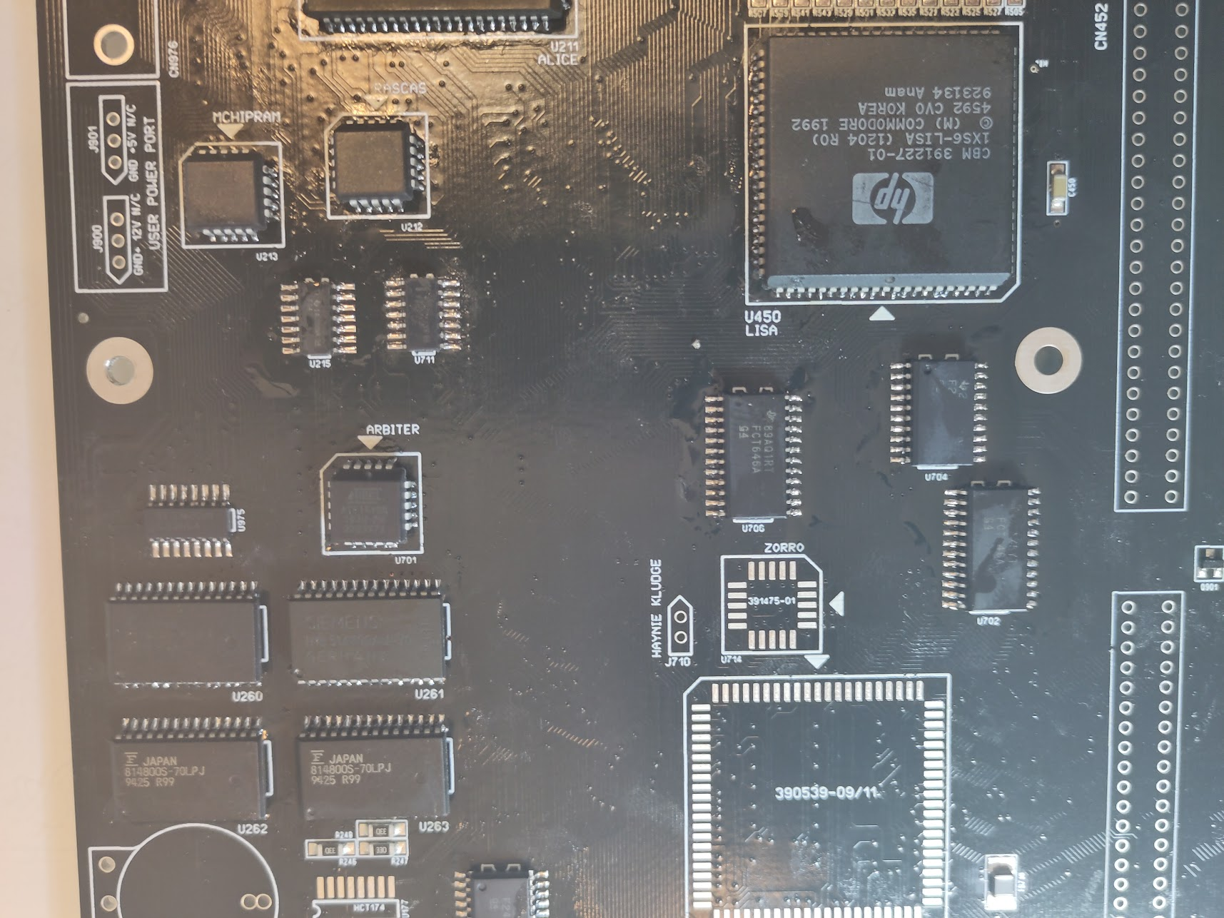
And we need to support some Zorrocards..
U714 (16V8)
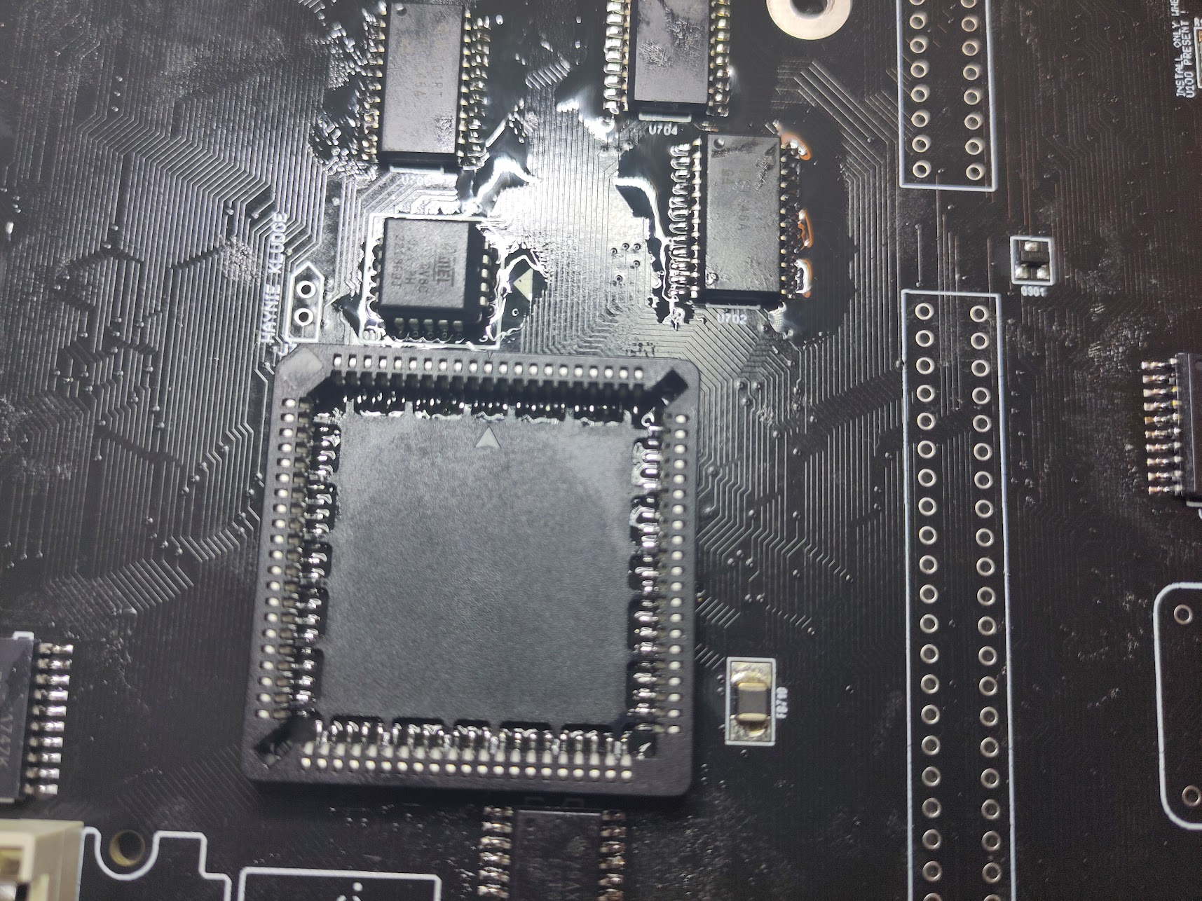
Buster.
I add a socket here. AND as always! AVOID SOCKETS if you cannot solder them. and IF you add a socket do NOT remove the inner frame as it is a important part of the socket stability.
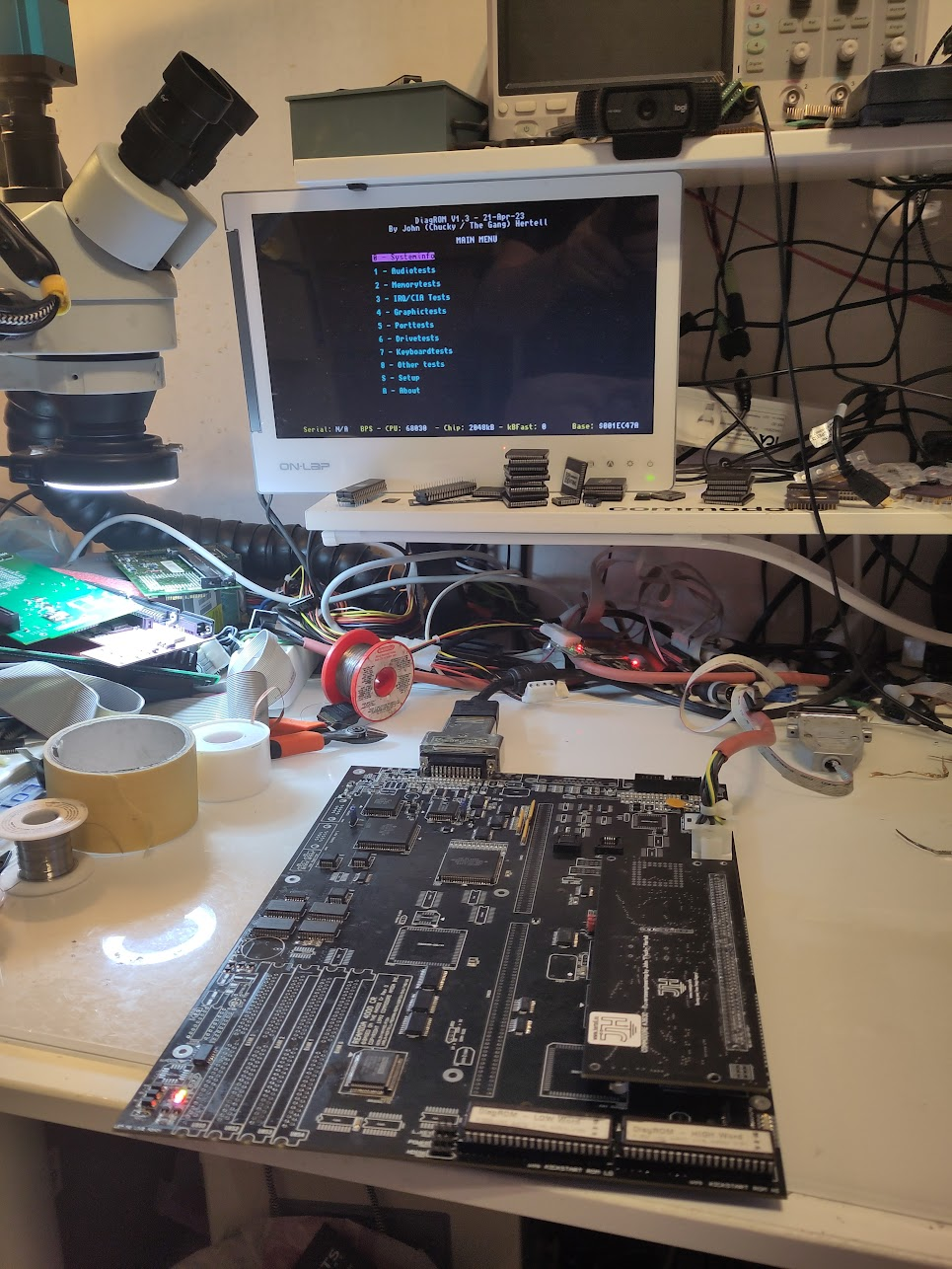
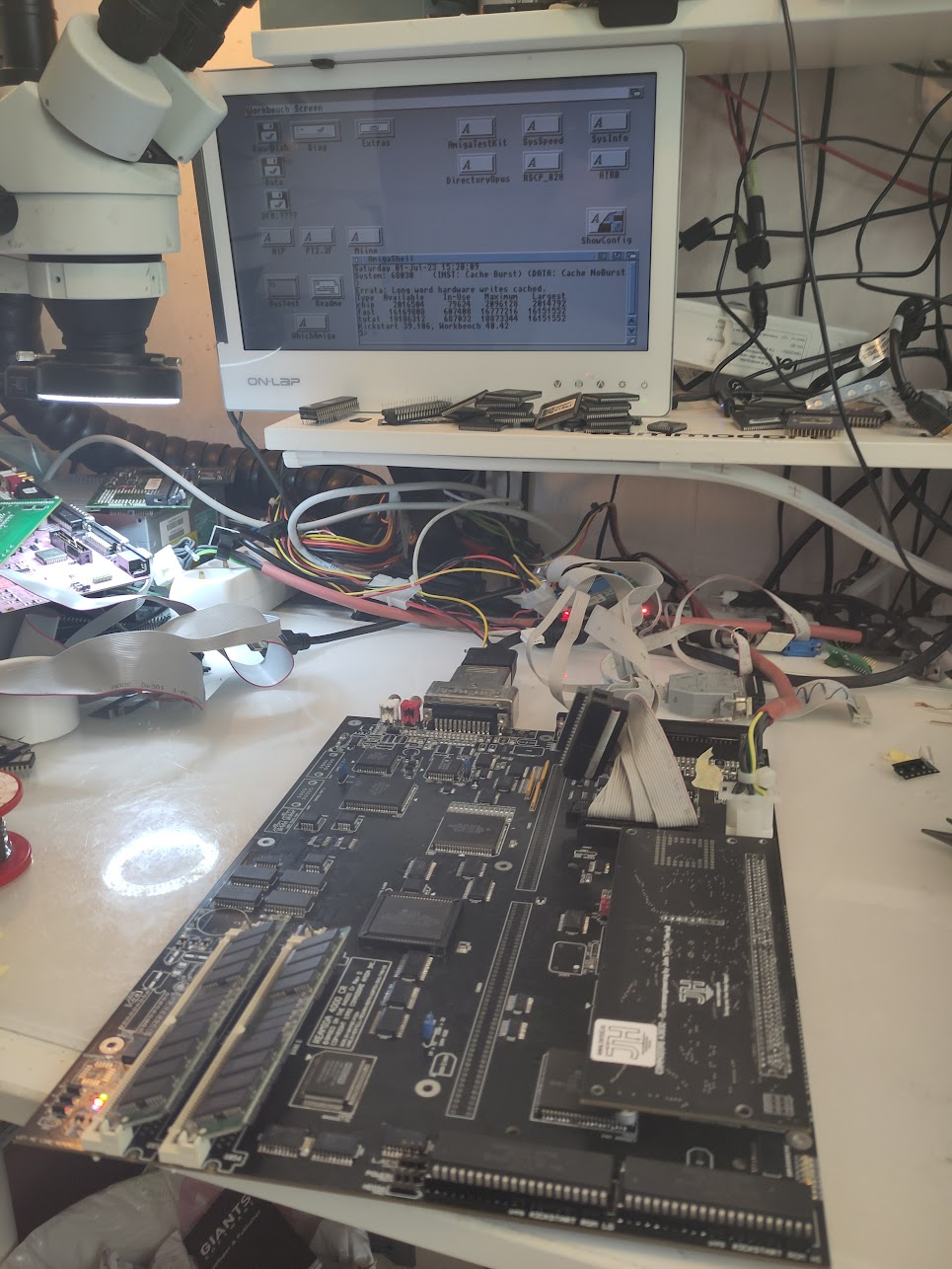
Now your machine should boot Workbench:
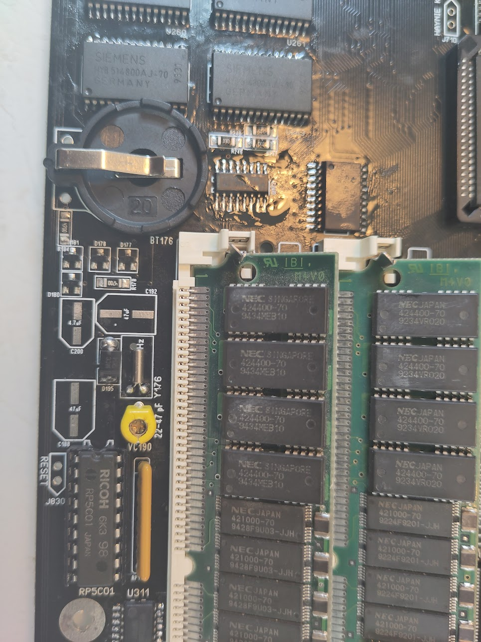
So some RTC:
Add
Y176
RP176 (10K 8Pin Bussed)
U178 (RP501C)
VC190 (22-47pF) (ACTUALLY this should be added after ultrasonic)
U177 (74HCT174)
I will do a separate post later how to adjust the VC190)
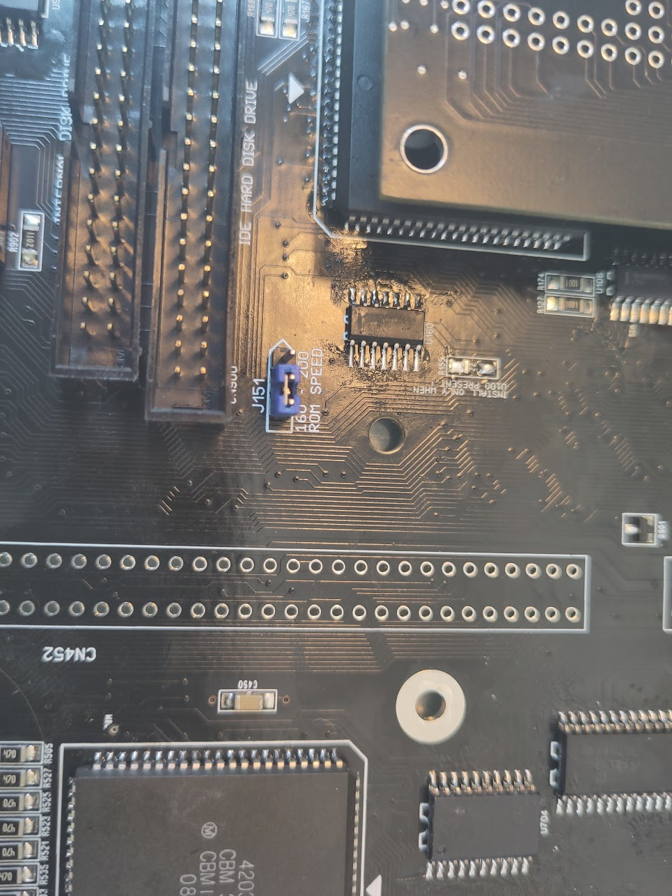
Now some more extras:
Add U198 (-5V Regulator), Keyboard connector, Rom speedjumper J151 (set to 160 or 200 dependent of your ROMs), and Zorro DB Connectors. 9Pin DSubs
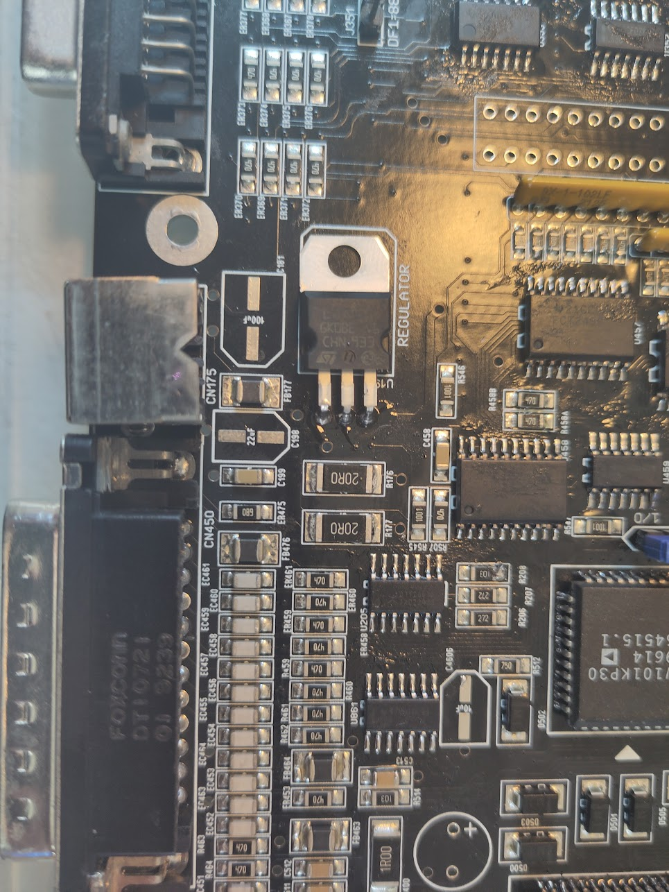
And your machine is “done”
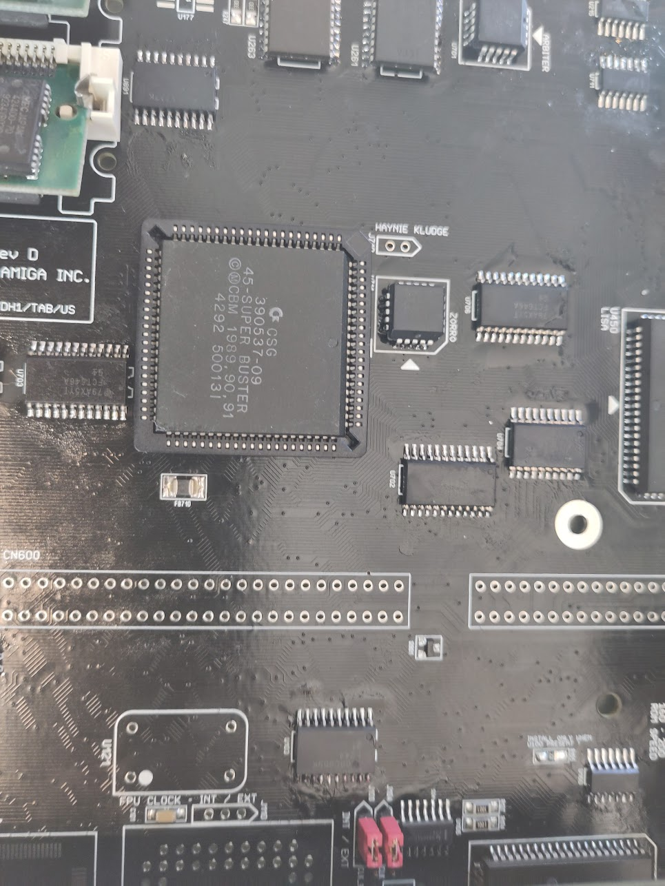
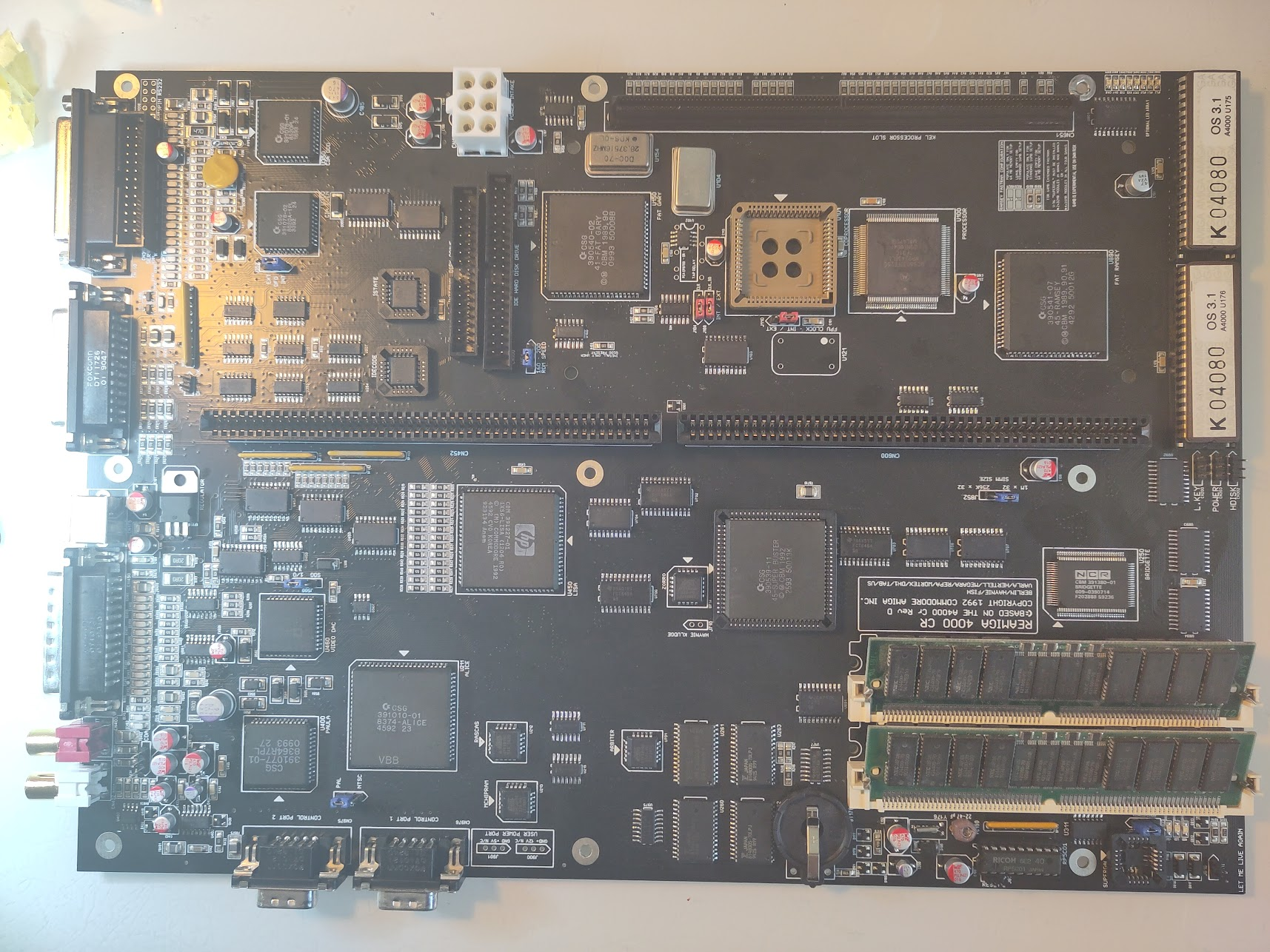
I just want to show a picture of the CPU part when the onboard CPU is used:
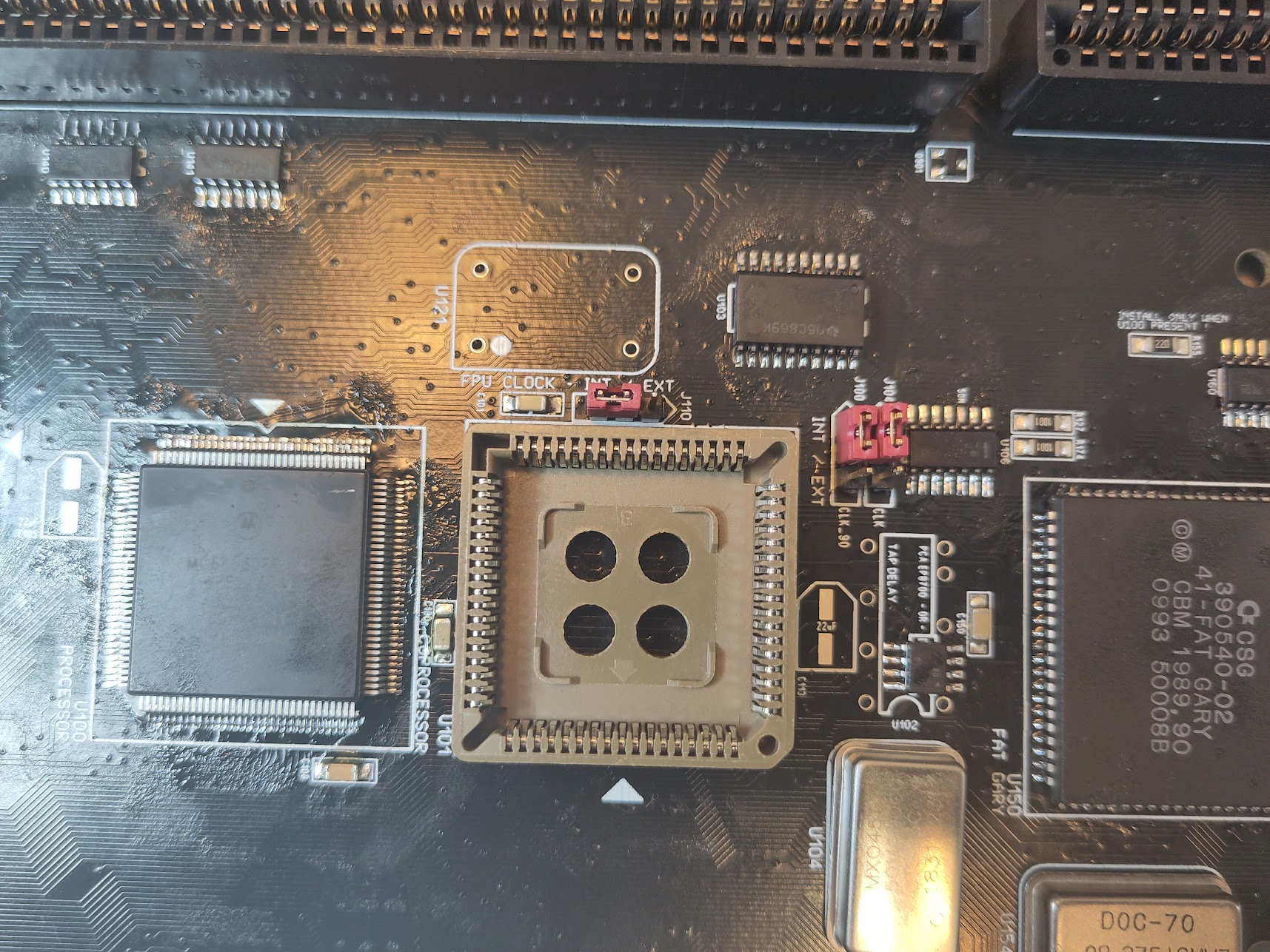
Here you see the CPU soldered on, and a socket for the FPU. and a jumper to select FPU Clock, this set to internal to use same as CPU clock, set to EXT and add a oscillator for a optinal speed.
And now some info about the new small extras:
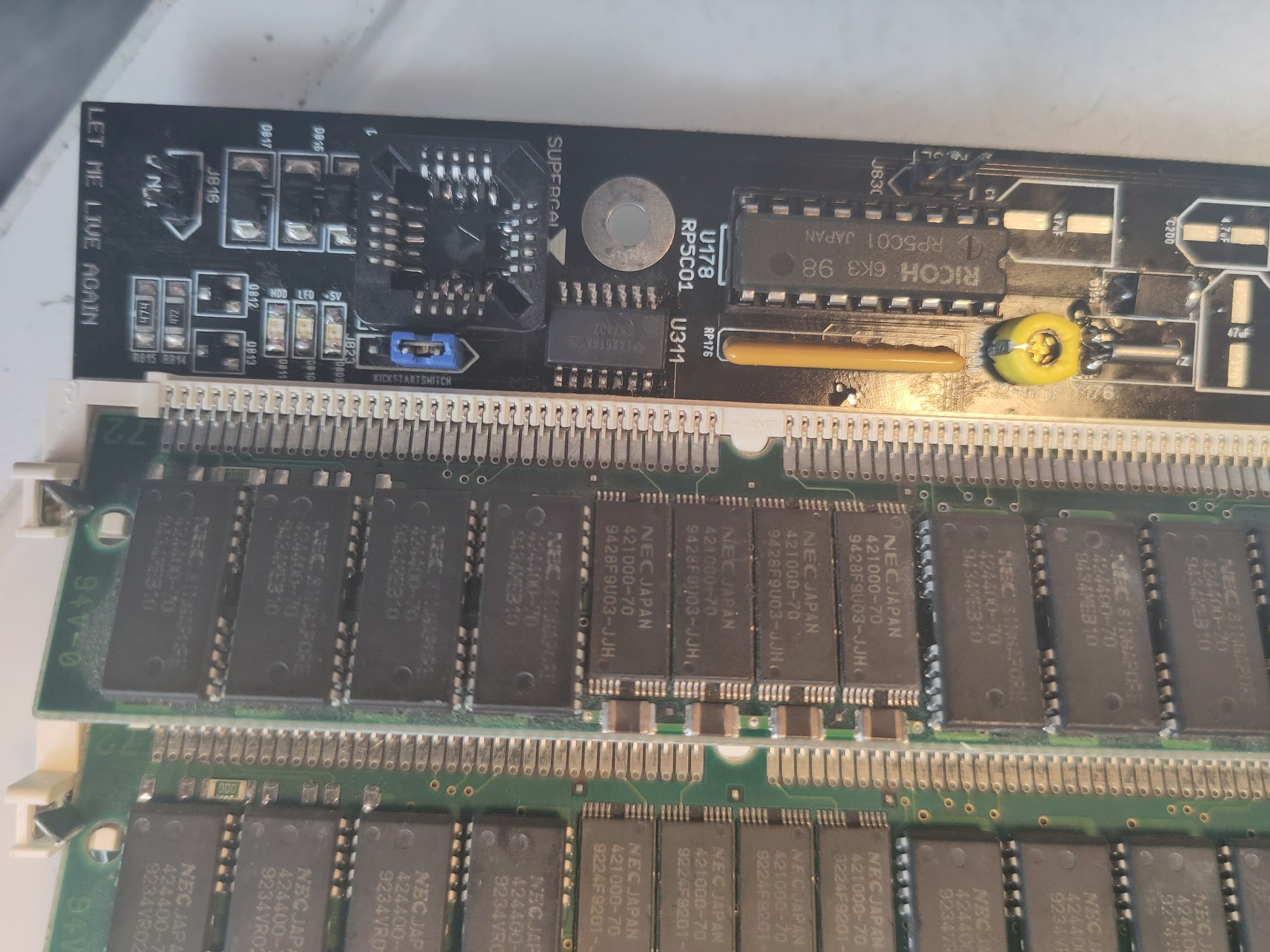
Here you see a picture of the “new” part.
the SUPERGAL is where you put the GAL for 64MB Ram if you use it. this is EXPERIMENTAL and might be unstable and not work in some configurations! it is all on you! ALSO note there is a verty tight space so U311 must be soldered somewhat moved” up to get a socket there. (will be changed in future revisions)
also maybe one diode needs to be moved.
so IF you use 64MB, add the GAL, remove resistors from : R818, R819 and solder 470Ohm resistors to U820, U821. If you have 4 simmsockets you can now populate with 4 16MB Simms. or if you use 2 simmsockets use 2 32MB simms.. when using the 64MB fetaure. you MUST populate 64MB ram nothing else.
Headers: J818 will initiate IRQ7 good fror programmingtools etc. (or makes just a PAUSE)
J830 is just a reset switch.
J823 is a kickstartswitch, if you use 27C800 proms then this switches between Bank1 or Bank2 on the kickstarts. this is why a larger socket is used.
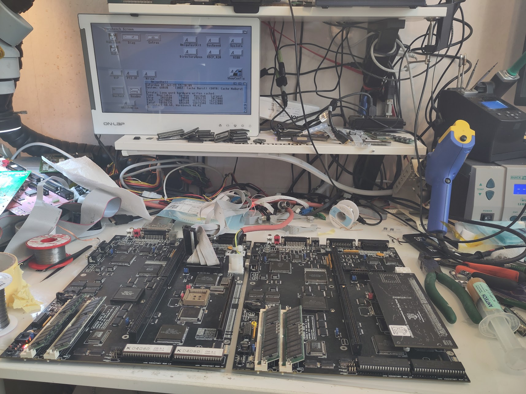
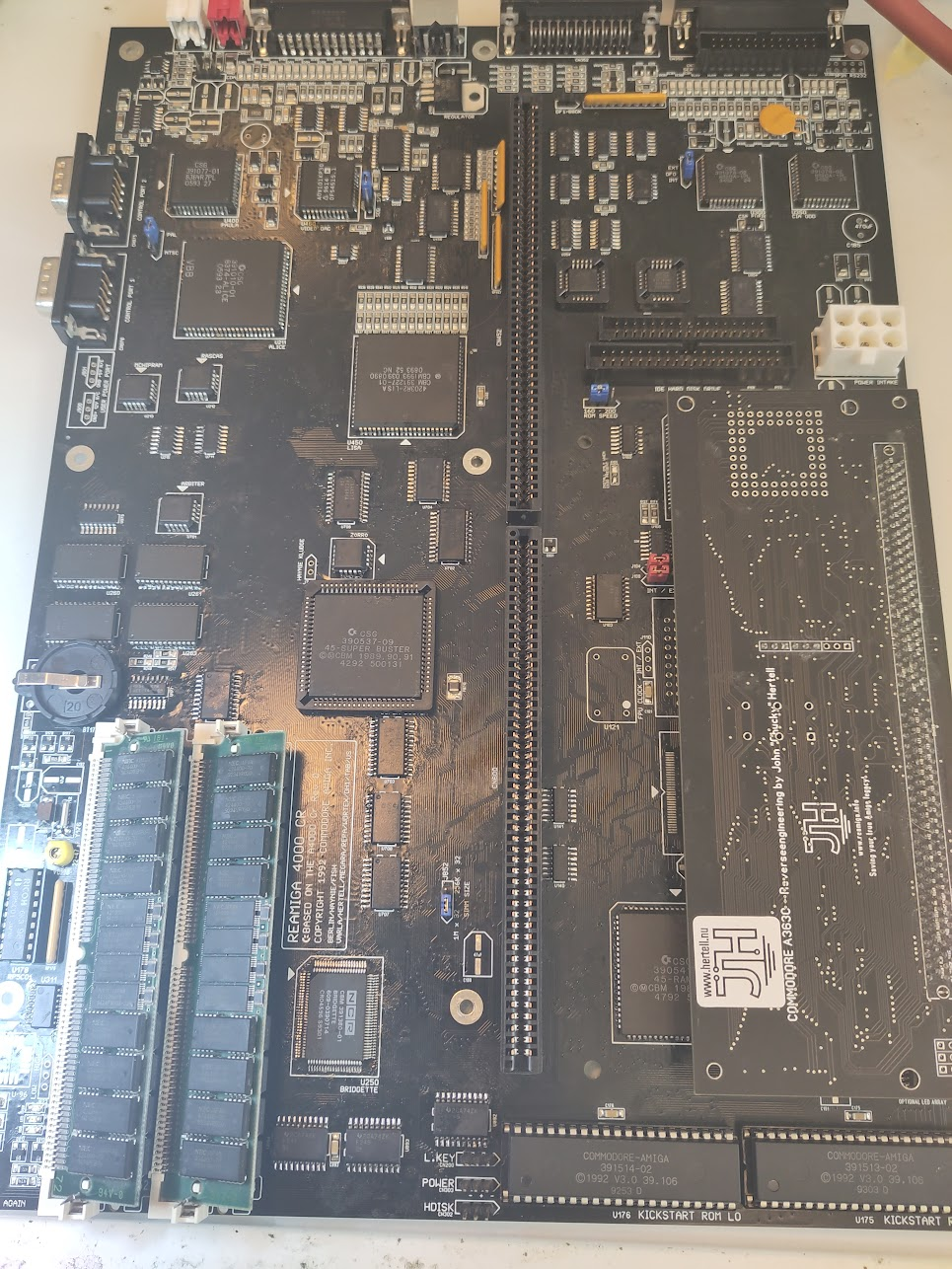
This is me testing 2 boards one with onboard CPU and one without..
Now time to clean the board, I do it in my Ultrasonic cleaner let it dry and THEN I add the Electrolytic capacitors.
AND my normal RANT: NO do NOT use Ceramic capacitors or Tantals. they might “work” but not designed for this location Especially not for Audio etc. Ceramic capacitors changes capacitance dependent on voltage and Tantal explode.. there are good highquality capactors (Hybrids, Polymer etc) use them!
Also notice that the 2 capacitors that originally on A4000 have the wrong polarity is fixed on this board.
Anyway thats it! all done!