It is time to release ReAmiga Rev 1.7
BUT! First as I also did in my video at: https://youtu.be/O4CJPtHMwOI a small writeup of the PCBs from PCB Way. https://pcbway.com
I did a Order via their Advanced PCB product to get a more personlized versoin of my ReAmigas.
There you have way more alternatived when it comes to colors:
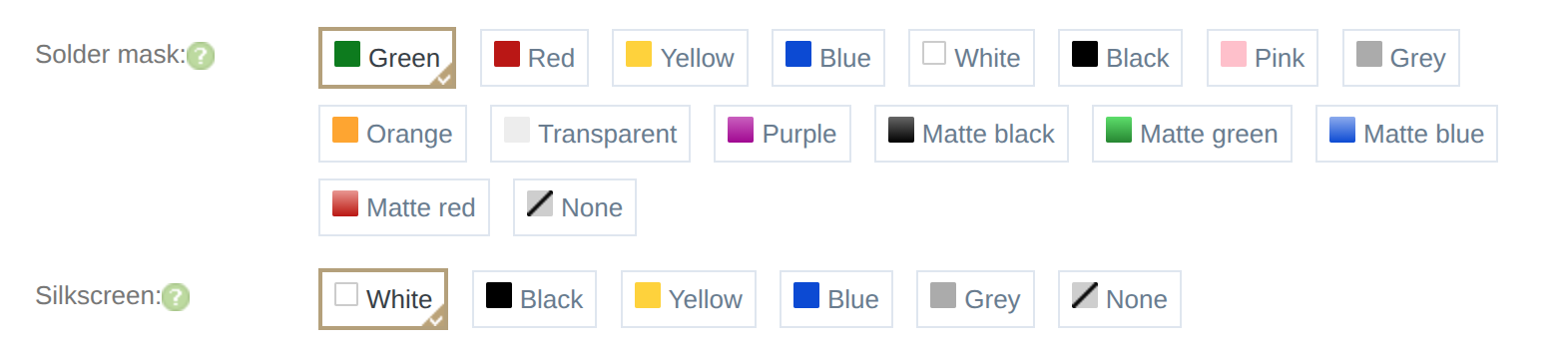
Sadly they do not have any photos how the different boards looks like. I would really give them a hint of having it. Anyway I chosed to do 5 in Grey and 5 in Pink!
So when I recieved my PCBs they looked like this:
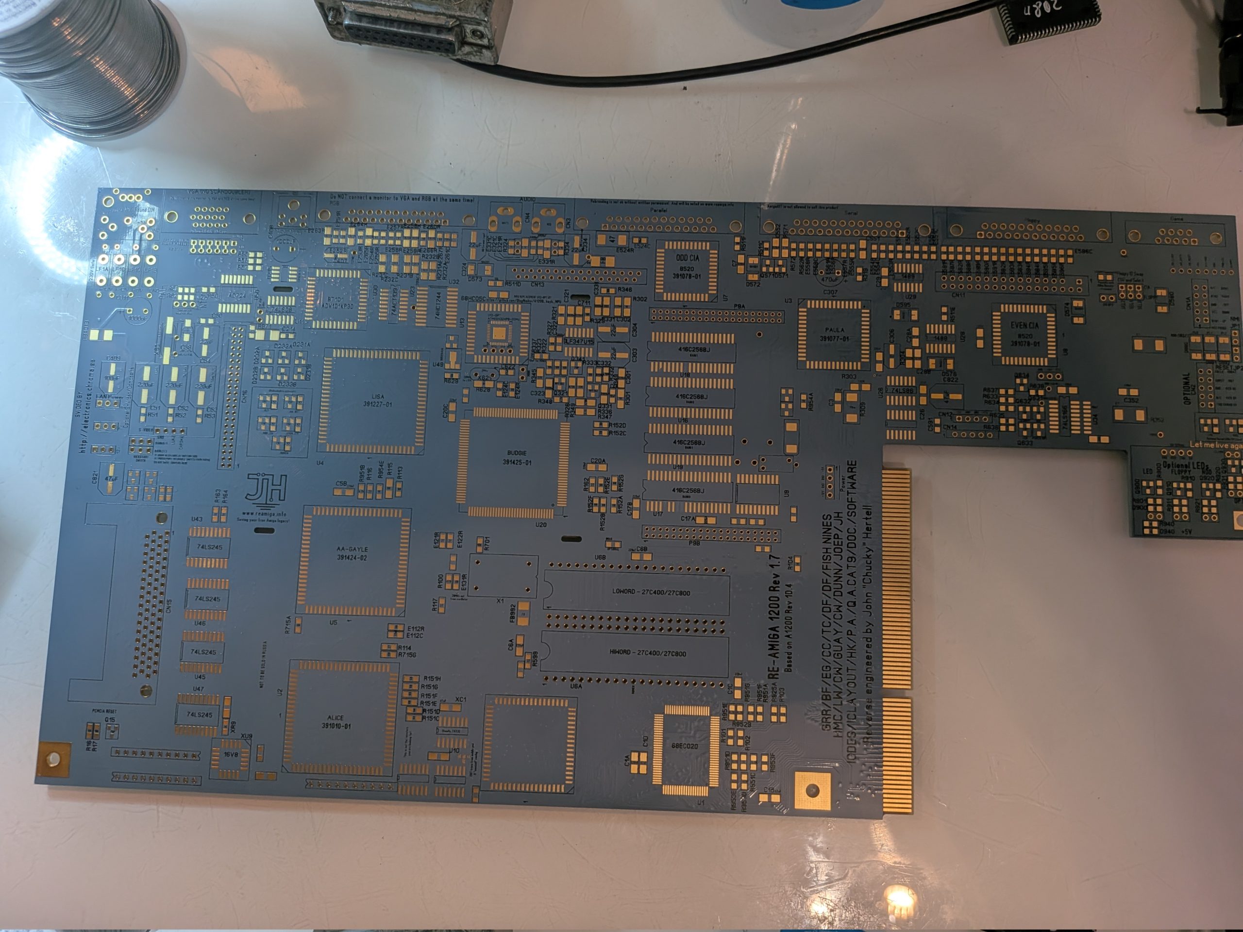
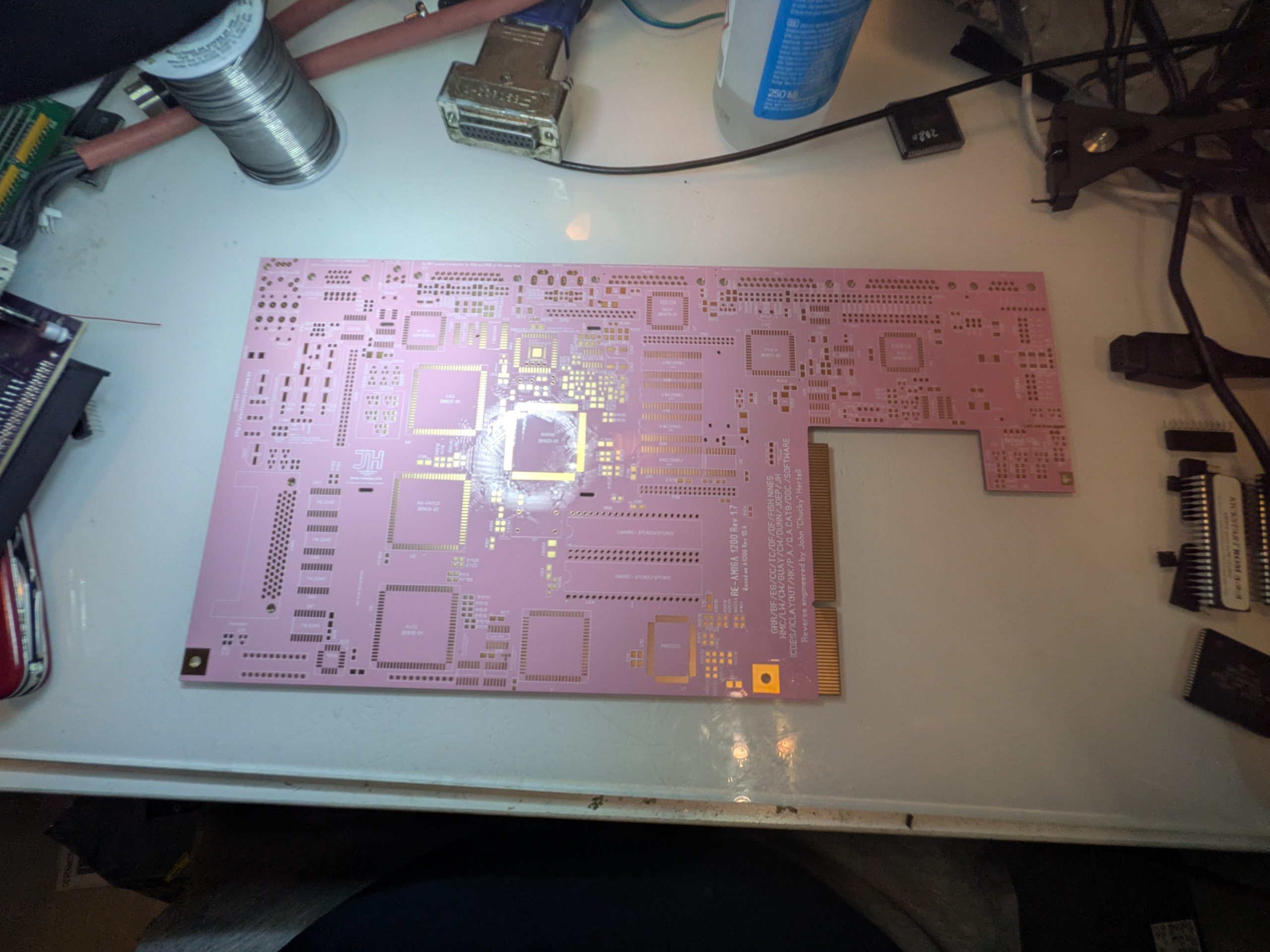
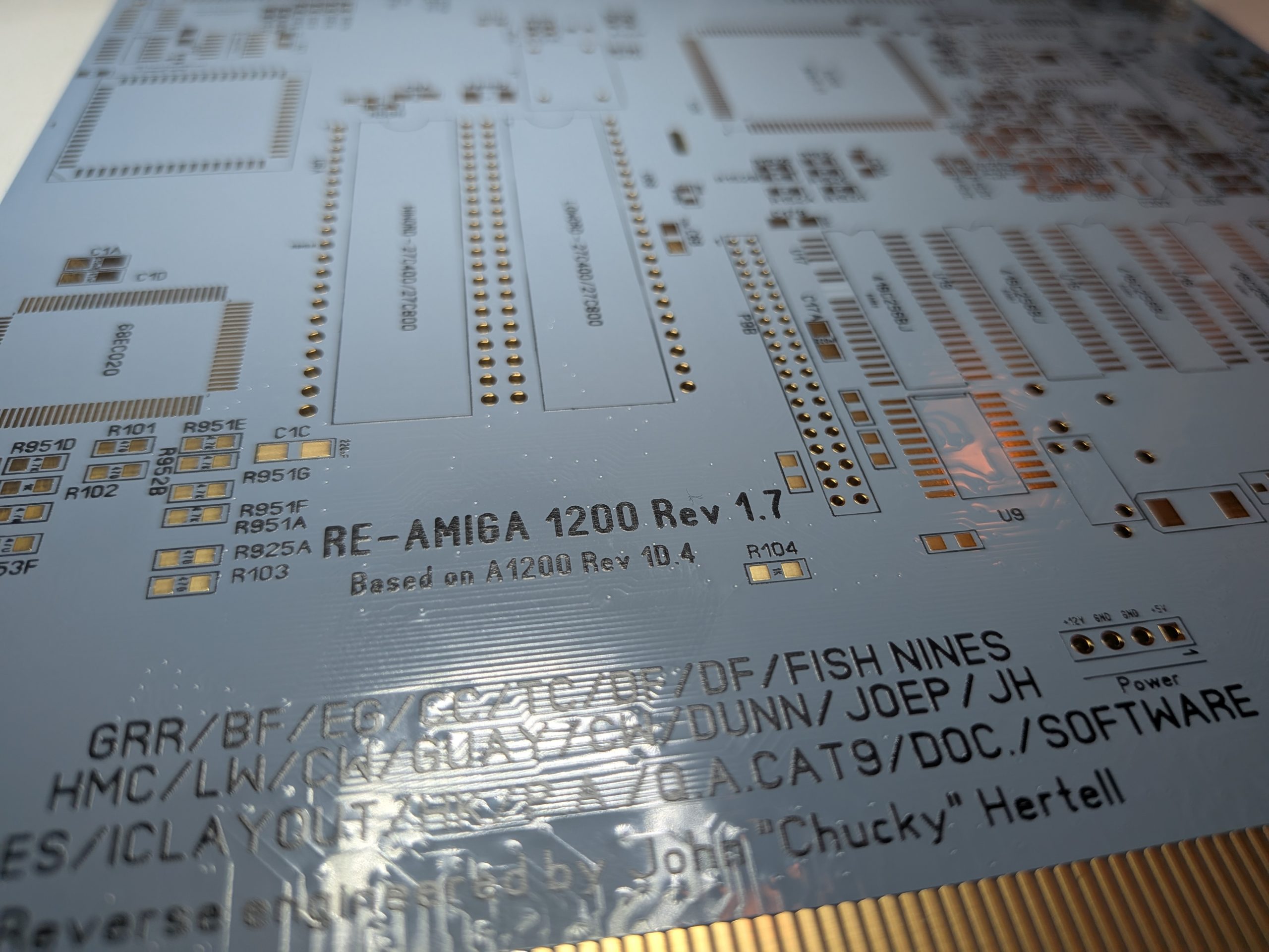
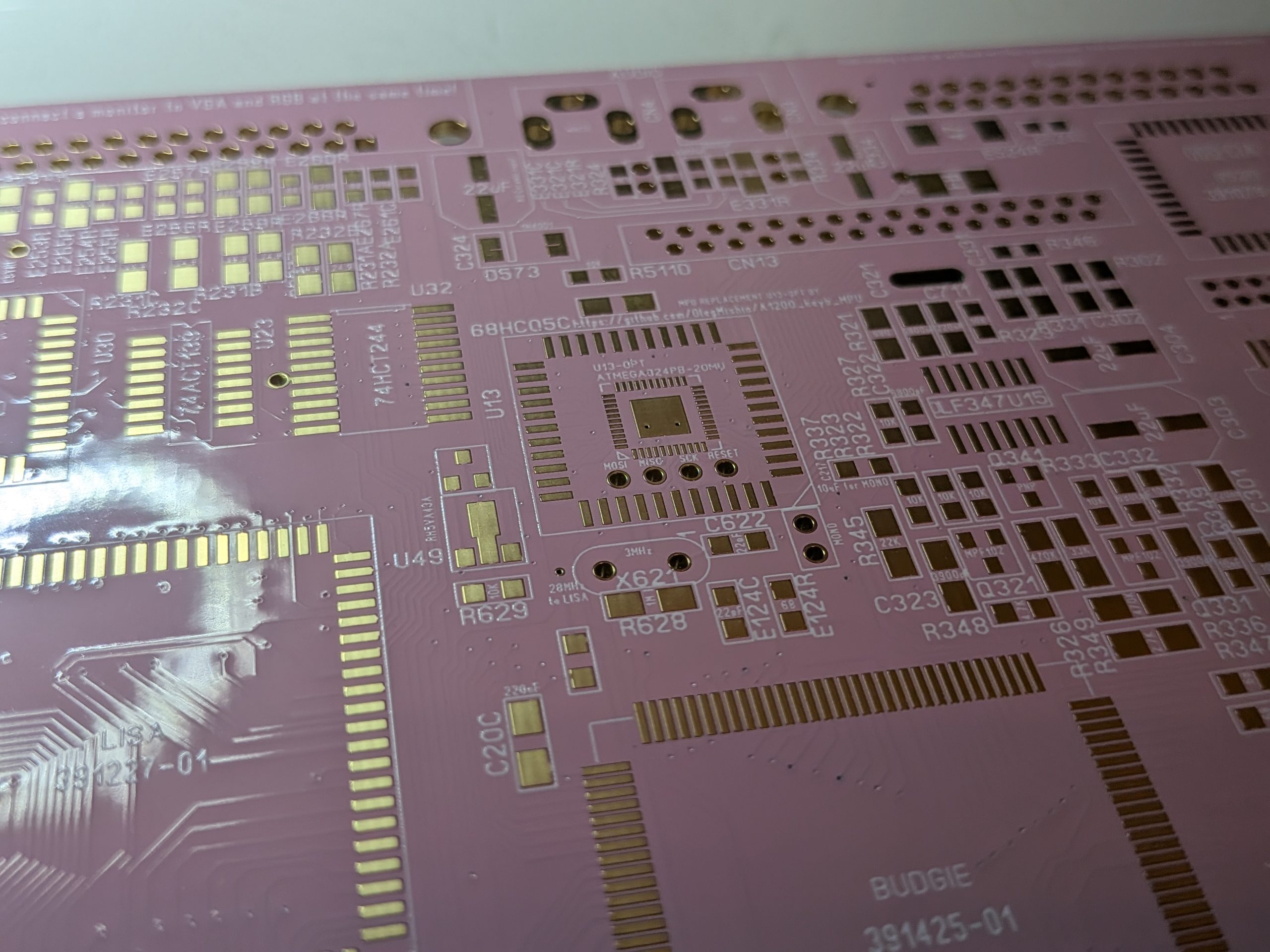
I must say that I just love those two. Quality feels fine and I have made 3 machines out of this and been working just perfect.
Also I asked them to do a bevel on the connector. Something that many boardhouses just skip especially when the “mousepart” sticks out.
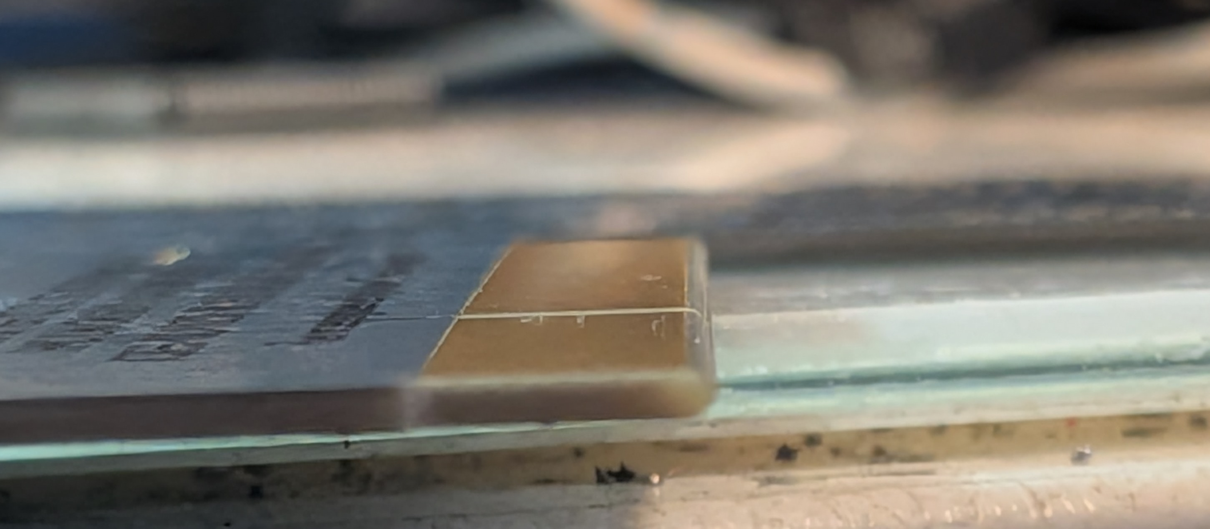
Maybe hard to see but as you can see. Just as it shold be. no 90 degree cuts damaging your CPU card when inserting it.
It might be on the more “expensive” side, yes. but you also get some testpapers with is. so they have done more tests compared to the cheaper version of the PCBs
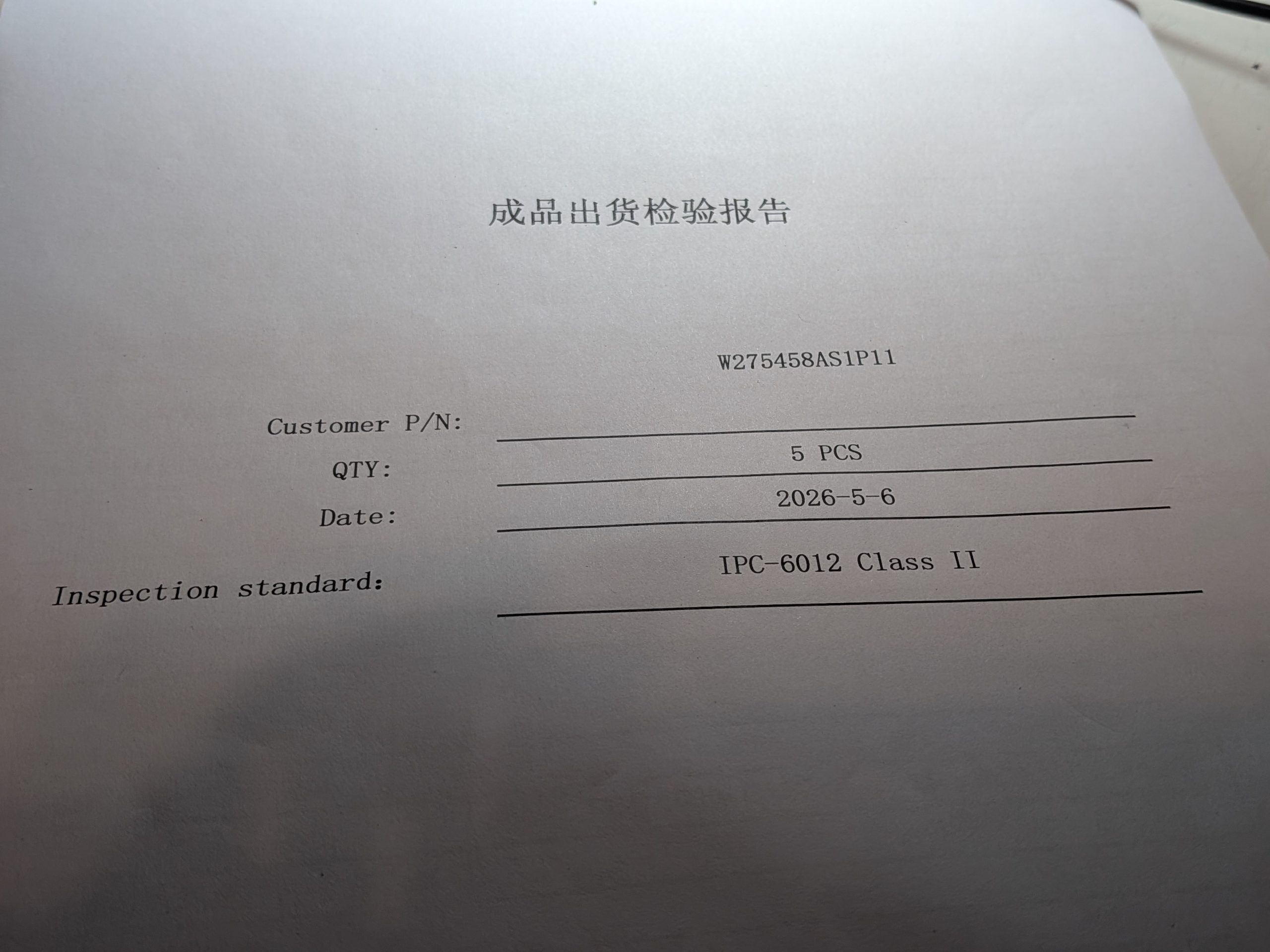
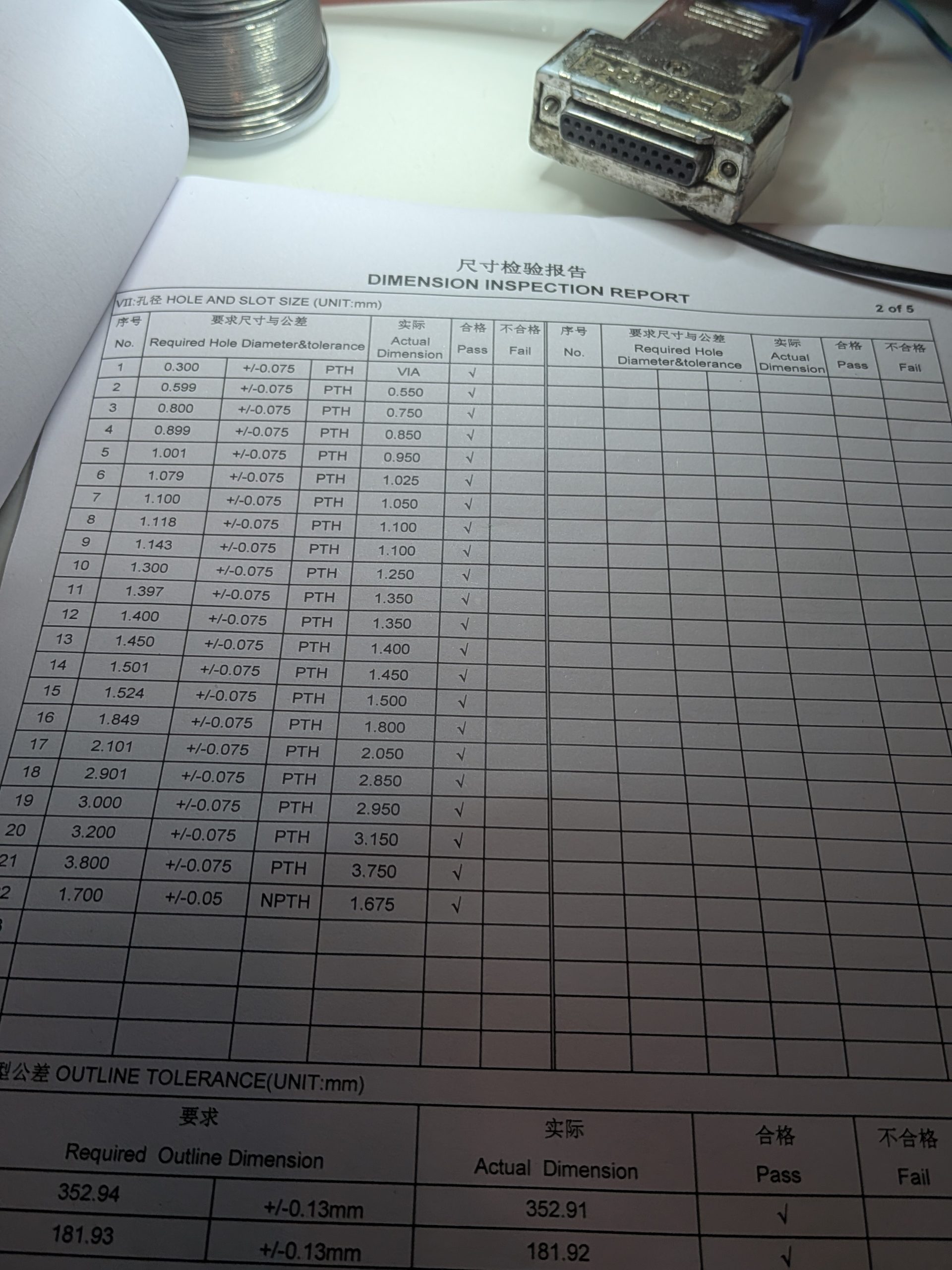
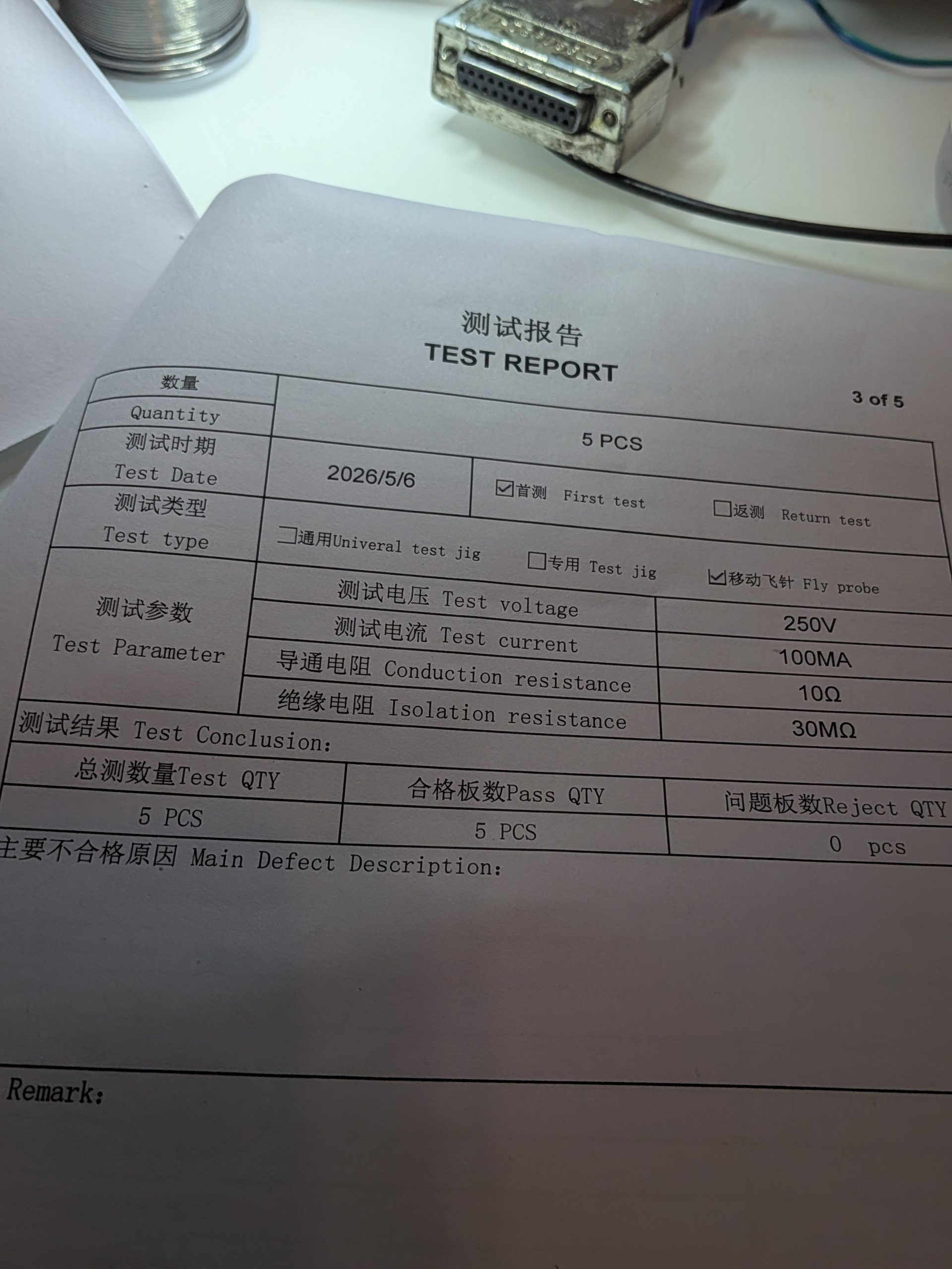
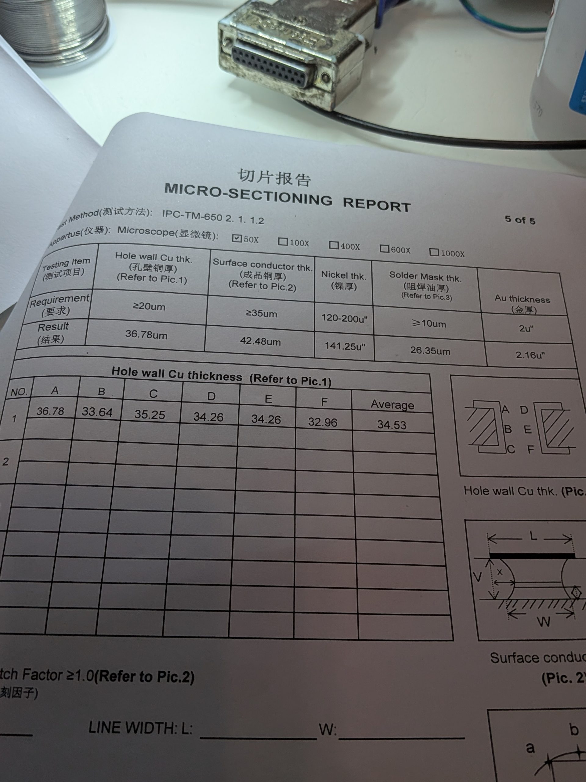
So. if you want something “out of the normal” yeah this is a really nice way to get your more personalized board.
ANYWAY! Back to the ReAmiga. You can find the files etc at: https://www.reamiga.info/?page_id=38
or quick version: https://www.reamiga.info/webfiles/R1200/ReAmiga1200Rev17.zip
BUT! lets talk about changes and the board!
At no special order at all:
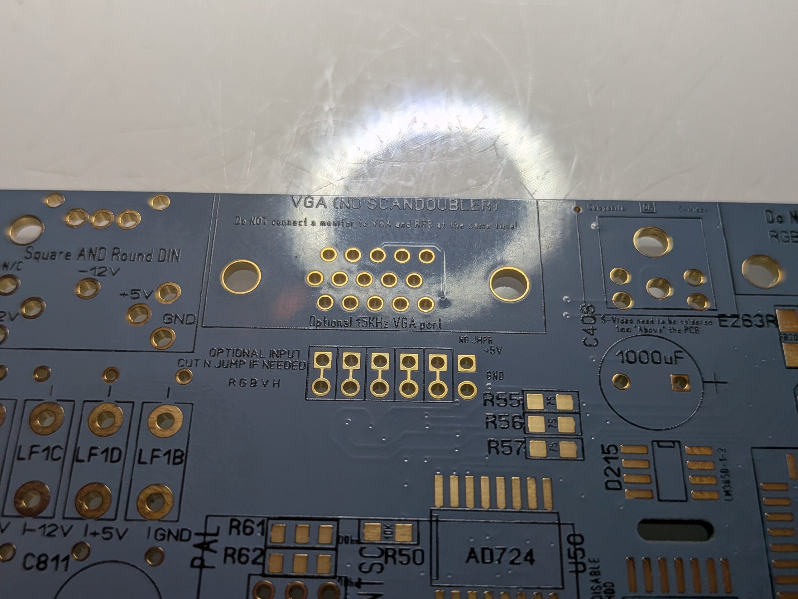
This is the VGA out. as you can see. i you do not need to do anything if you want the old ReAmiga behaviour. Connect your 15KHz compatible VGA monitor and. Just use it! I would however NOT recomend using VGA and RGB at the same time. as then the signal would be too weak.
BUT! NOW if you take a look at the header. first 5 pins are shorted. but IF you cut those wires.
the bottom row will be what comes out of the Amiga and the top is what is sent to the VGA port.
so if you have a internal Scandoubler etc. you could cut those 5 pins. and inject from your scandoubler to the top row. and now the VGA connector would send out data form your scandoubler.
ALSO you can see there are pins for GND and 5V. this is if you want to make something that needs power. like a “VGA Signal enhancer” or whatever. then you can pick up Amiga signal from lower like. do some magic and sent to the output. All up to you! Remember that H and V sync signals are alredy buffered on the ReAmiga (EVEN on the RGB port!)
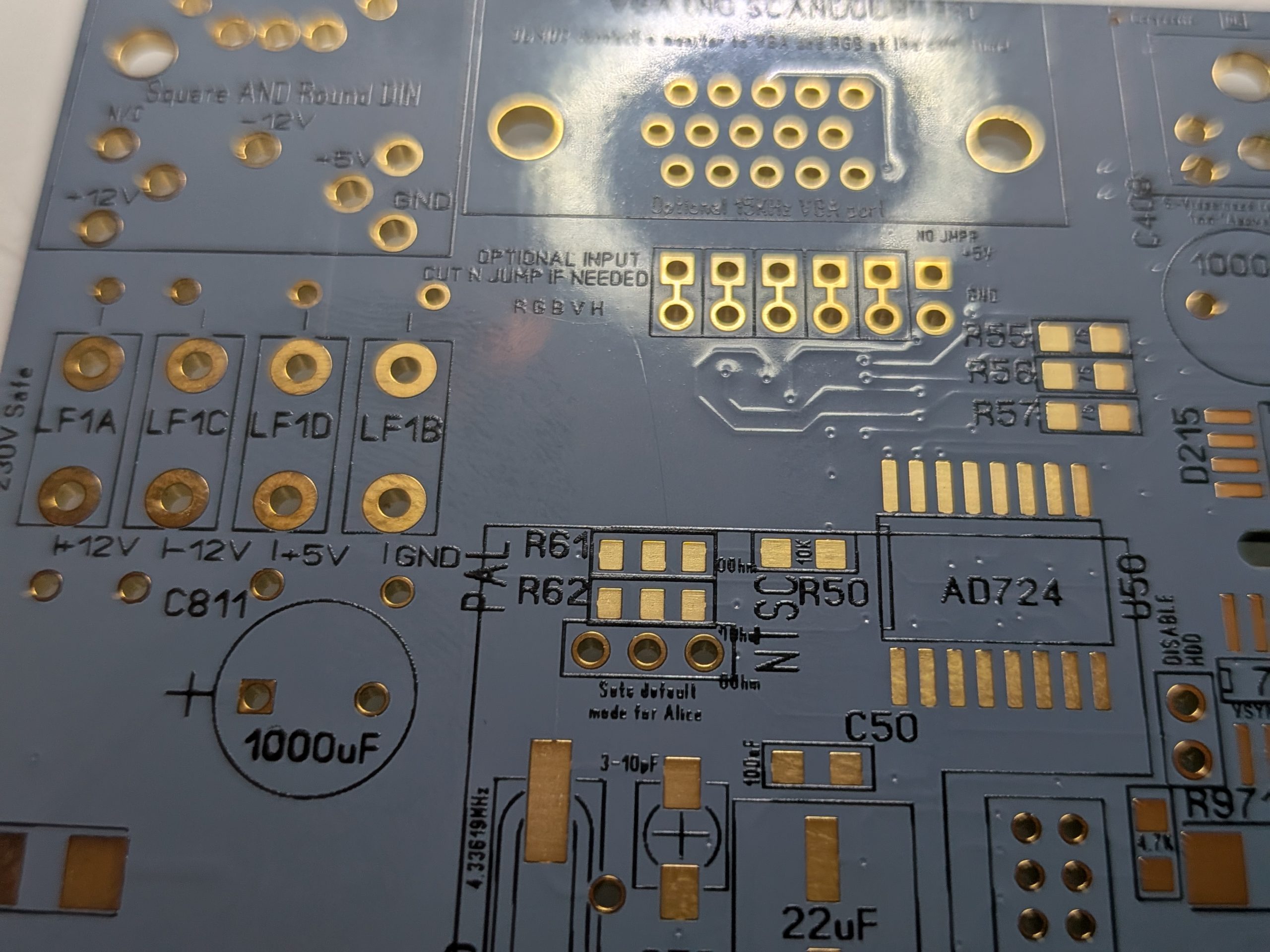
R61, R62 and jumper below. this is the PAL / NTSC Switch. the first 2 are how the Composite signal is handled. so a 0 ohm resistor between middle pin and PAL or NTSC set how it shold behave.
IF NTSC you can skip the 4.3KHz oscillator
Jumperheader is to tell Alice to start in PAL or NTSC mode.
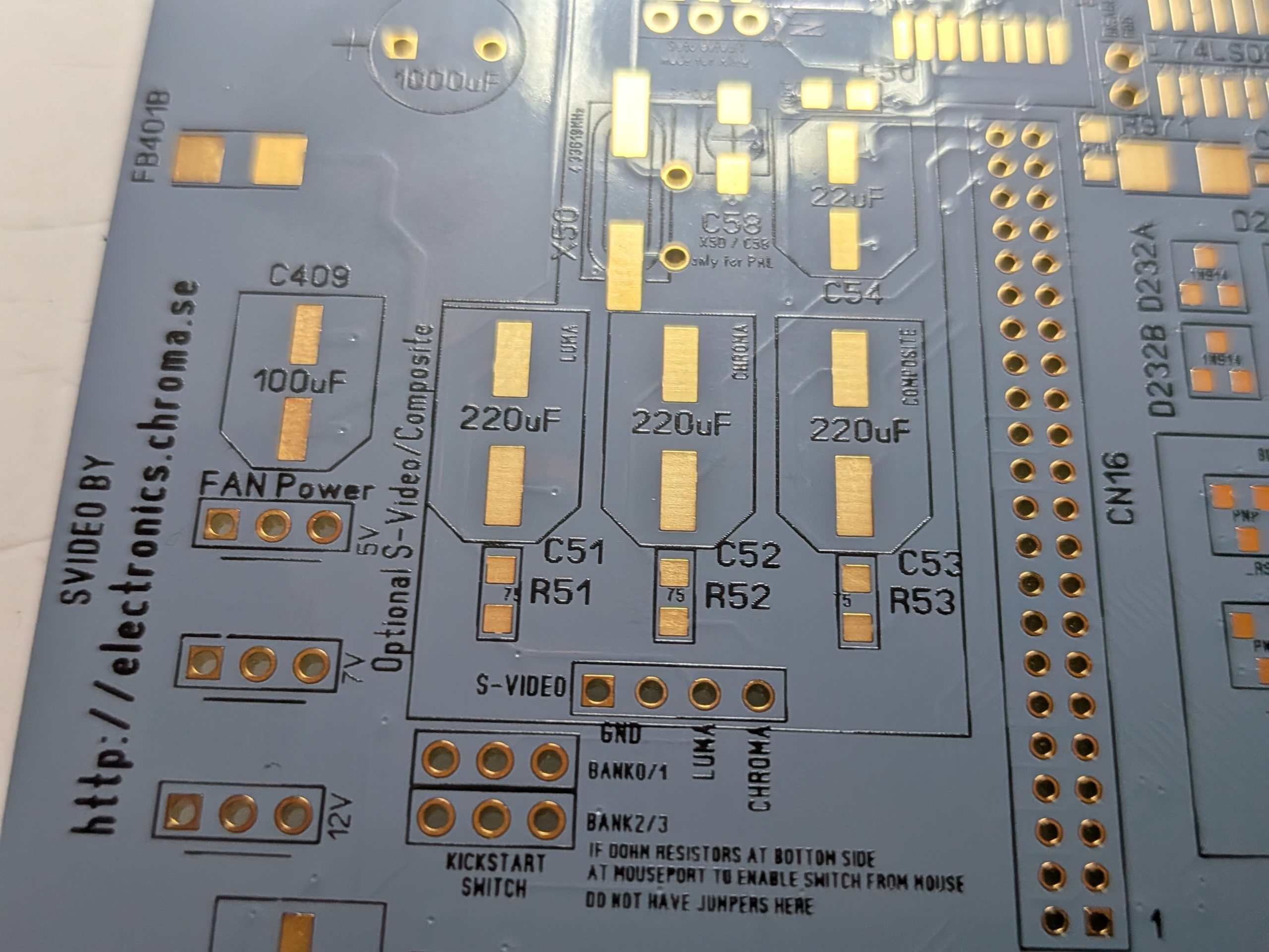
Here we have 3 FAN Connectors. for 5V, 7V or 12V also S-Video connector if you do not use a Svideo as edge connector. you can add a connector here for it. Now Also 220uF caps are marked what they are used for. so no need to solder them for SVideo if you do not use it etc.
also 2 headers for the Kickstartswitch. this is IF you have a 27C800 or 27C160 (forgot to print this on the PCB. sorry) with severeal kickstarts programmed into it. so you can change what kickstart. With original kickstart ROMs those jumpers does not do anyhing and could be skipped.
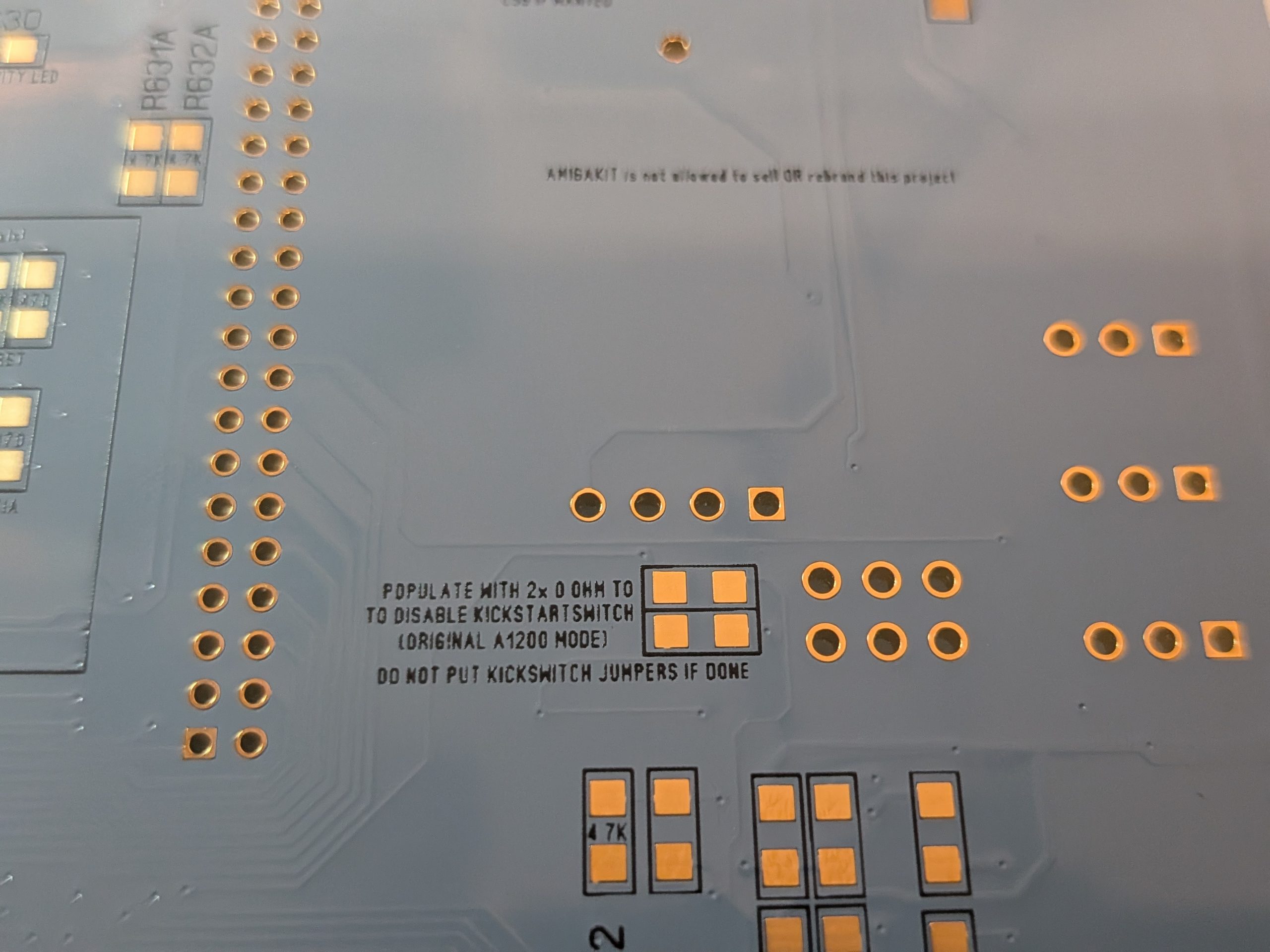
On the backside of the board. if you put a 0Ohm resistor here you will disable the kickstart function. and you should NOT have any jumpers attached. (actuially I would recoment NOT to add headers)
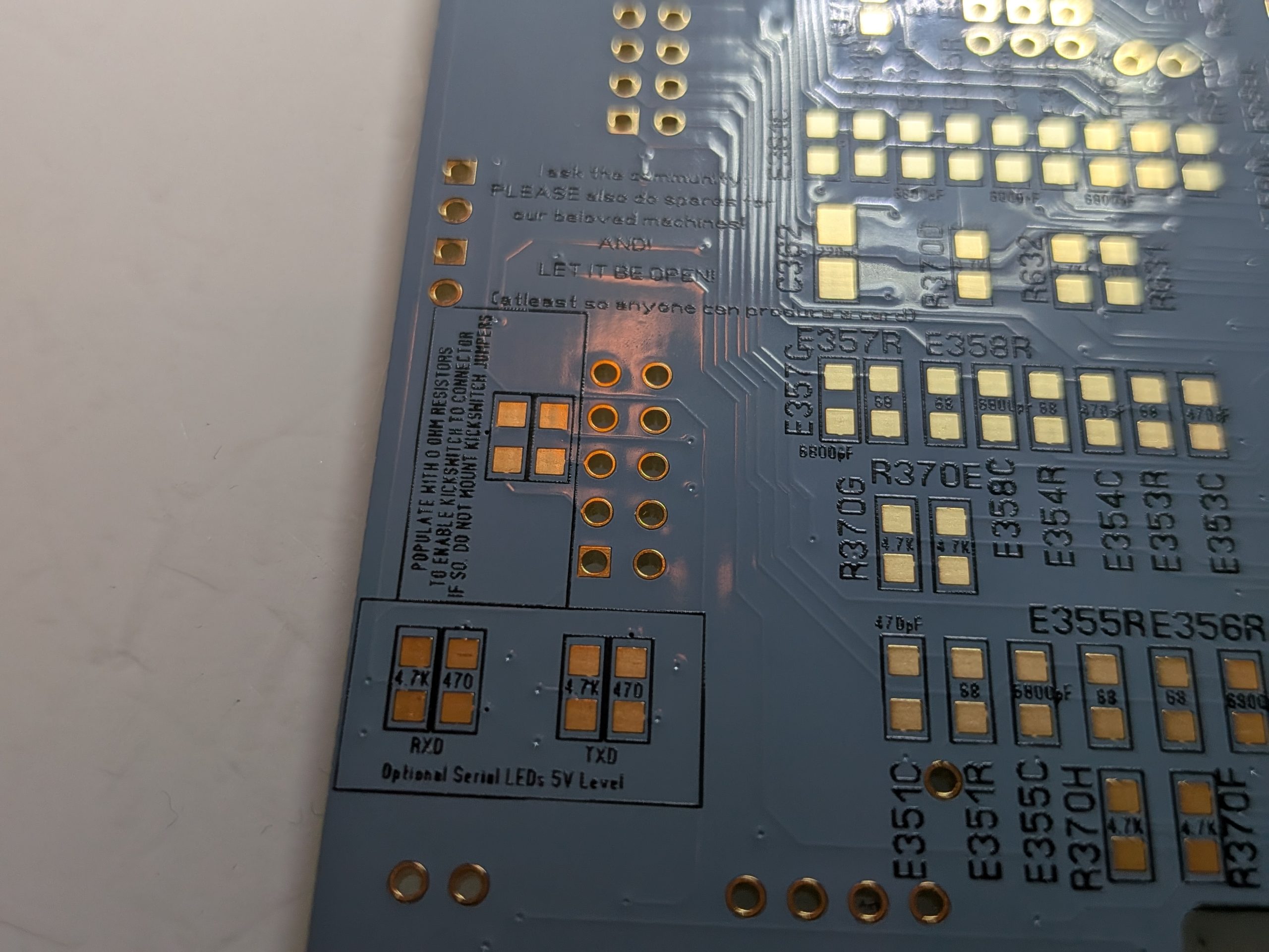
On the bottom you have also those. this is to let the kickstartswitch to the optional “mouse” PCB. as you might want to control the switch from anything connected here. IF you have it. I would receoment no kickstart switch headers. but absolutly NO jumpers!
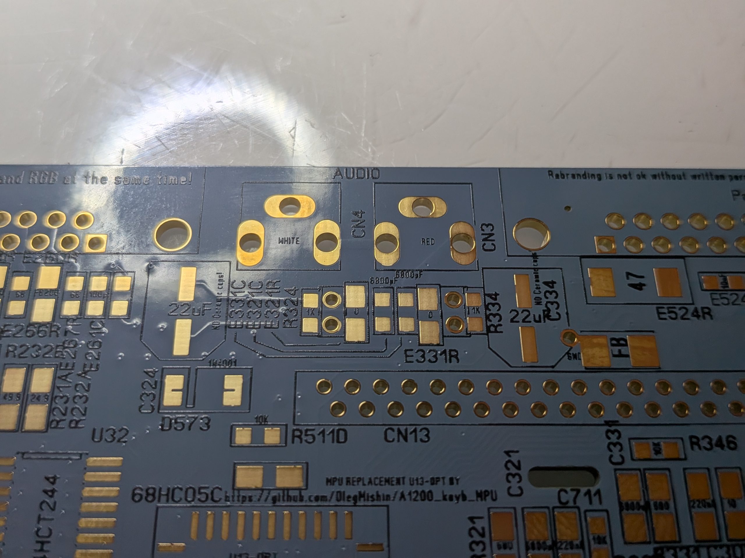
At the audioports there are some headers. this is to REPLACE the 0Ohm resistors you see. this is most for card like Warp1260 that can inject its 16Bit audio into the RCA ports. so instead of 0Ohm resistors. add a header. connect a jumper. or wires when reading the Warp manual. Bottom header is Amiga signal. top is what is sent to RCA port. also a pin for Audio GND
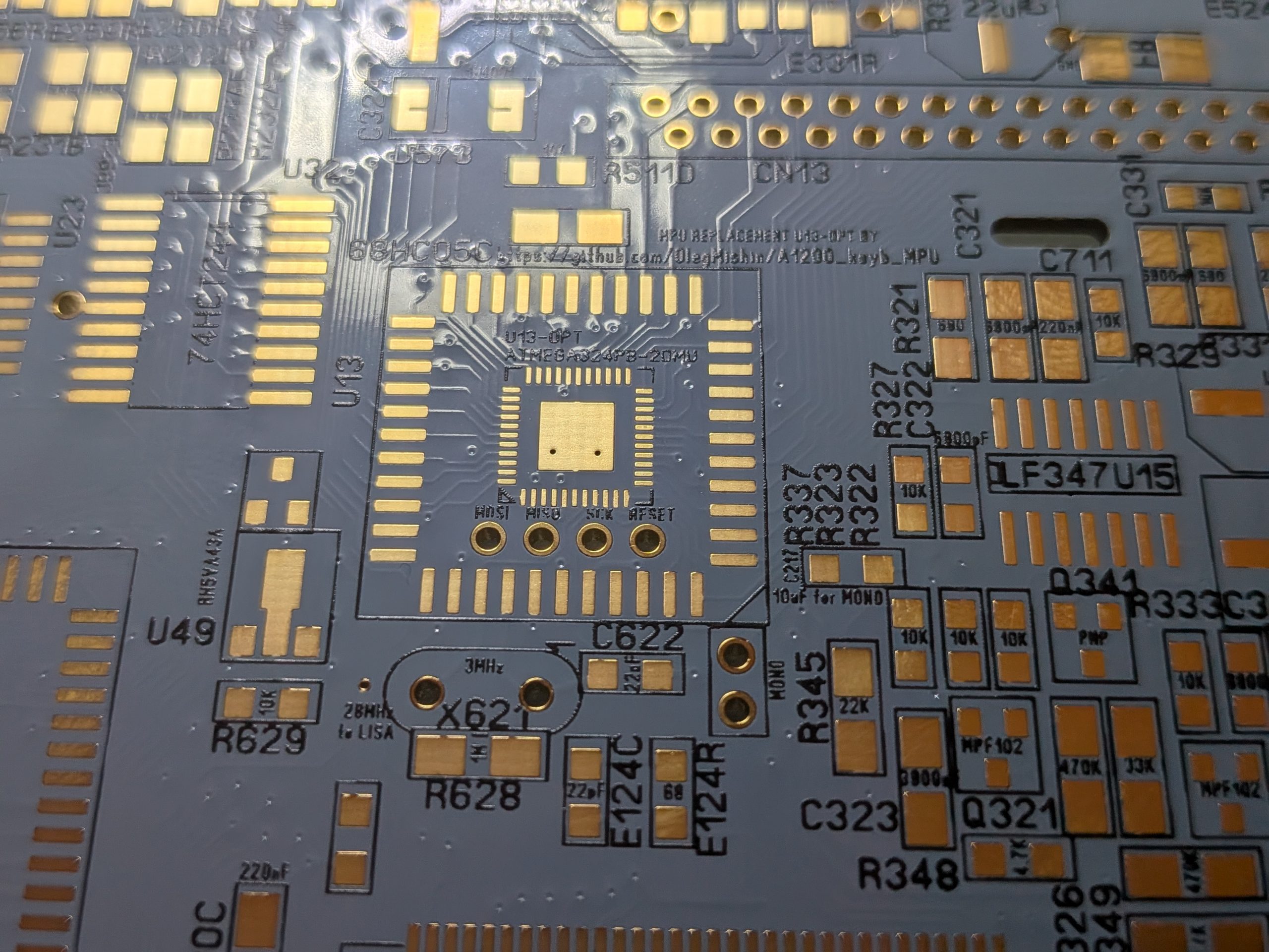
THIS is the biggest new of Rev 1.7 a possability to have a replacement MPU.
based on project by : https://github.com/OlegMishin/A1200_keyb_MPU
IF you use this, you can skip the 3MHz oscillator, the U49 Low-volt detector. but you need to add a 10K resistor at other side of the board.
I will make a special instruction how to program this.
You will also see a “MONO” header this is mono audio if you need it. Attach a 10uF cap at C217 for it to work.
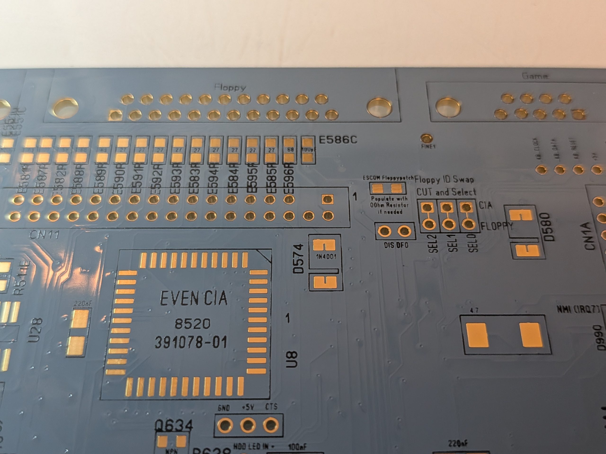
Some headers here. “ESCOM Flppypatch” add a 0 ohm resistor and it will be the ESCOM PC drive patch.
DIS DF0 will disable the look for a DF0 floppy at boot.
SEL2., 1 and 0 having it like it is and floppy work as normal. cut the wire between 0 and 1 headers and make a cable as a cross. as DF0 and DF1 changes place.
Also you can see a header for 3 pins. this is for switches like the RATTE Switch.
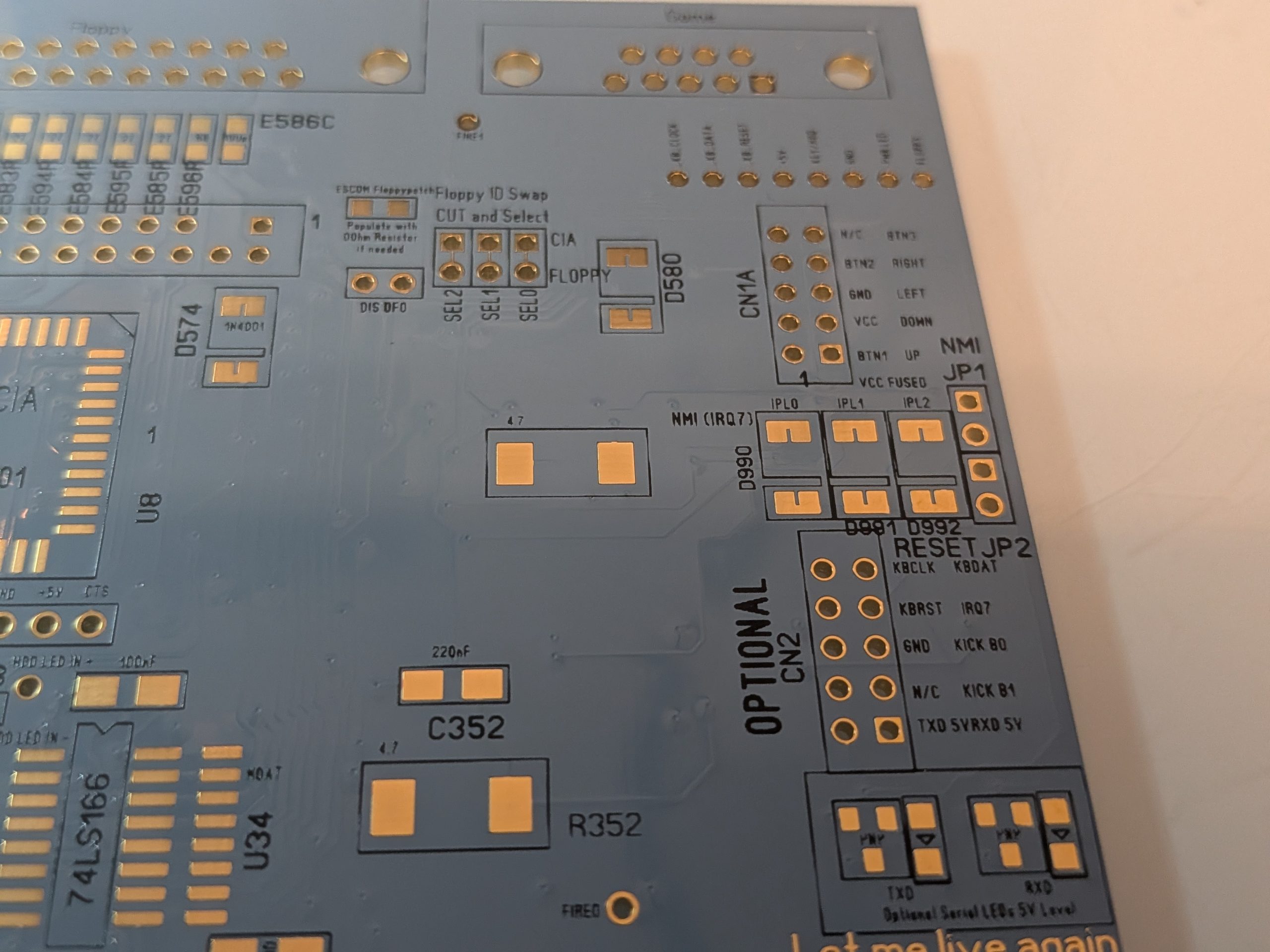
The Mouse PCB have now 2 connectors. IF you want to use a normal Amiga mouse. you do not need to use the bottom one. BUT! if you want to use a USB mouse AND Keyboard you can use like the project:
https://github.com/arkadiuszmakarenko/RISKYREA1200
This is a project that allows you to use USB mouse and Keyboard. ALSO with (a not so tested yet) possability to swap Kickstarts described above. also IRQ7 possability.
This is OPTIONAL! USB mouse is NOT required. normal Amiga mouse works just fine with the 9Pin DSUB solution included in the ReAmiga archive (OR A1200 Rev 2 original Amiga mouse connector)
OR a stright header up and 9pin dsub like on original rev 1.4d boards.
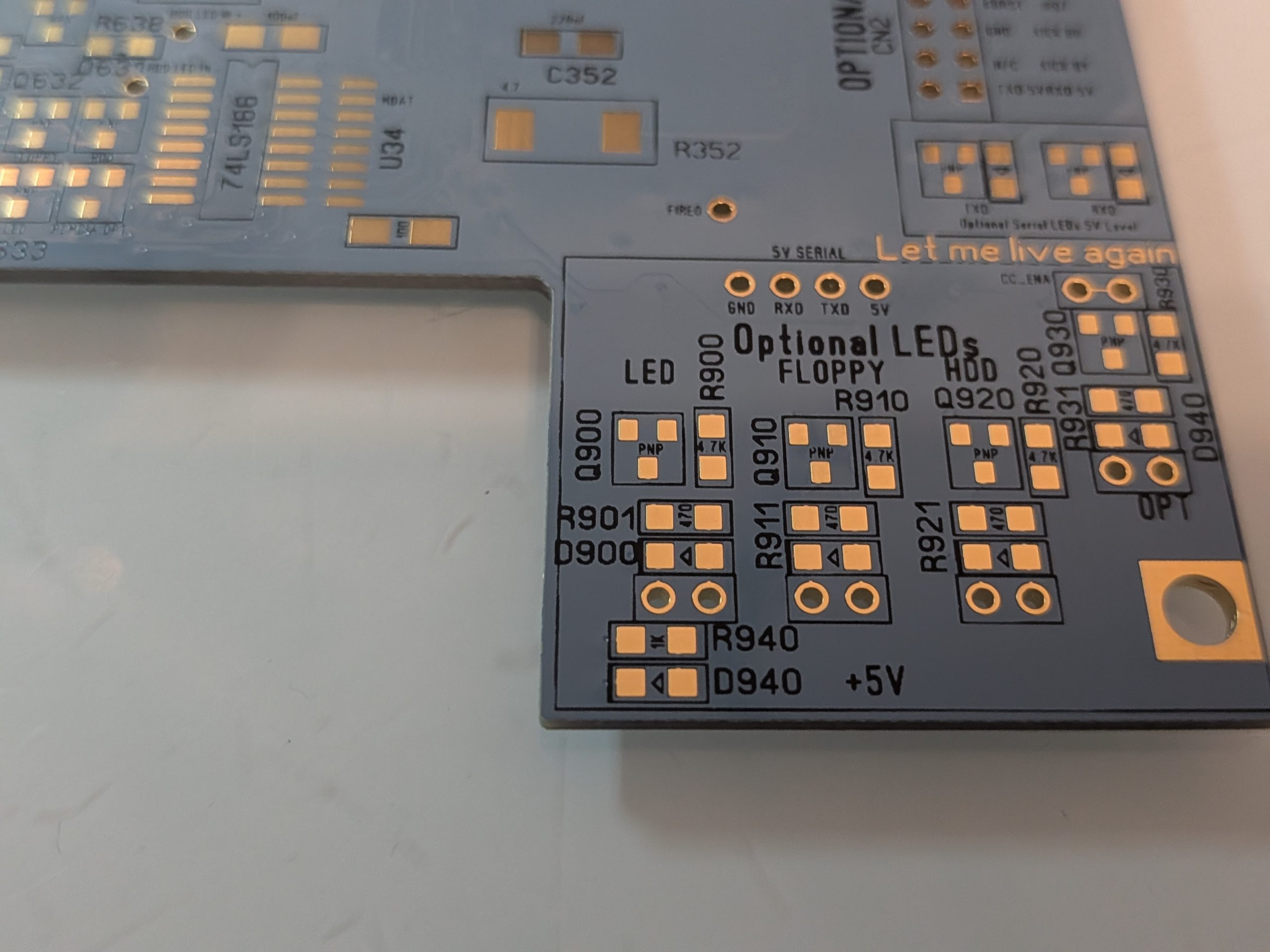
Lets talk about those headers- in 1.7 I have connected the connector above directly to pcmcia activity, if you want anything else there connected to it. cut the trace and connect whatever you want “OPT” to flash on to the right pin.
There are headers for LEDs. you can connect leds here, but the YOU CANNOT solder leds on the motherboard.
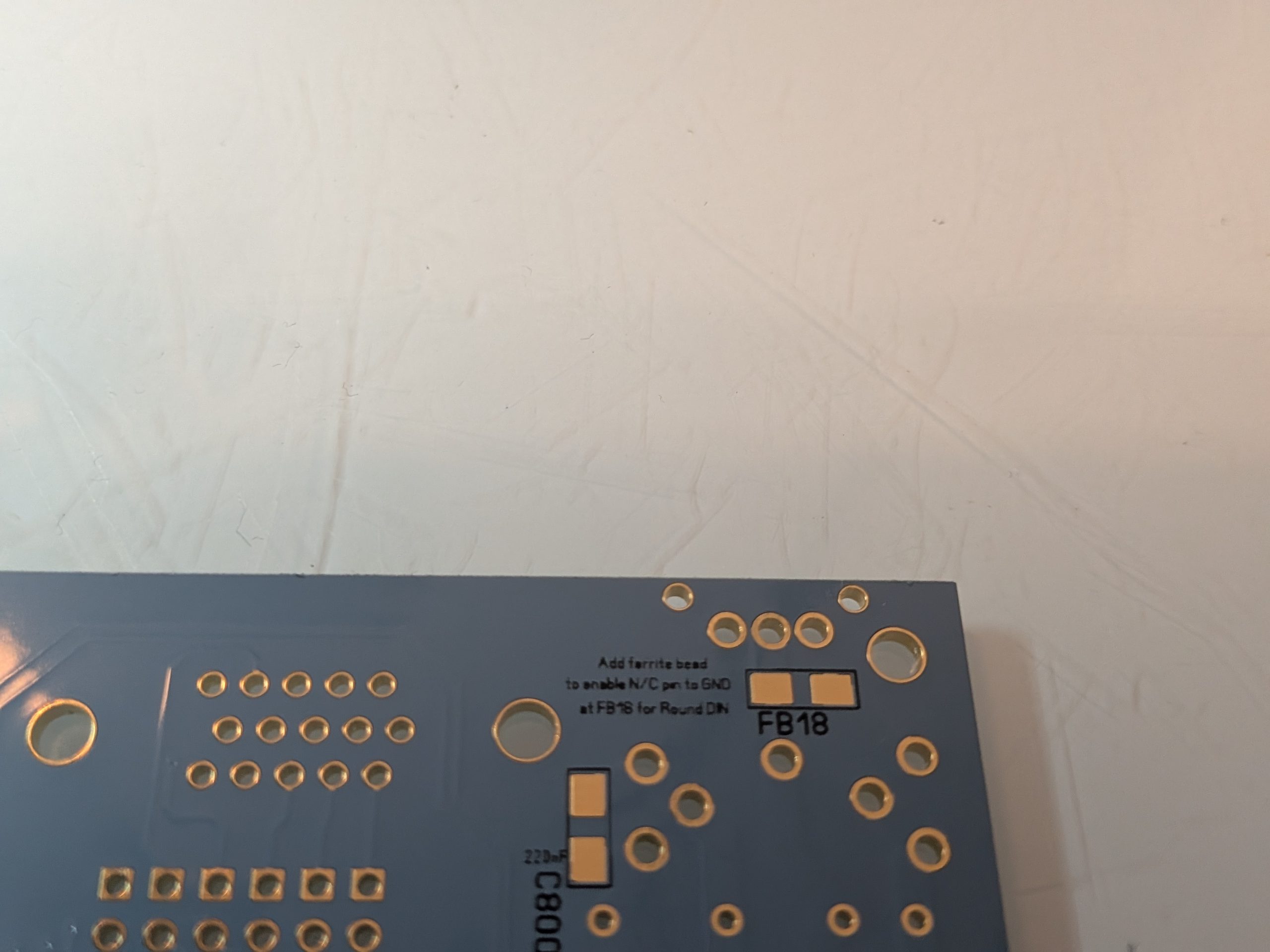
Final note. IF you are using a ROUND Connector for power. Add a Ferrite bead here (similiar to all others on the A1200) BUT ONLY WITH ROUND Connector. do this with the square one and attach a original 1200 PSU and you will have a direct +5 -> GND short and magic smoke WILL appear!
OK NICE! but I have seen information about an ReAmiga 1.5B what is this?
When I did my first testorder of 1.7 I got pinged about this. A nice cleanup and he have made a really good job in some cleanup. and GND islands etc similiar to the original 1200. BUT as I already have made a testrun of 1.7 and finilized it. I could not use his data as that would cost alot more to do even more testruns etc. This is a case of bad timing. he is all OK of doing and even sell boards with it. but as I have nothing to do with it. it will be exactly as Rev 1.3 (done by the guys at A1k ) I will NOT give any support.
NOT as I think it is a bad project. absolutly not, but I havent worked with it so I cannot support it. simple
What happend to Rev 1.6?
it was actually a project including most of 1.7 (except MPU) but the kickstartswitch was broken. so header 2 needed to be disabled by the 0 ohm resistor soldering. there was only like 5 sold. I did that disable on all boards.
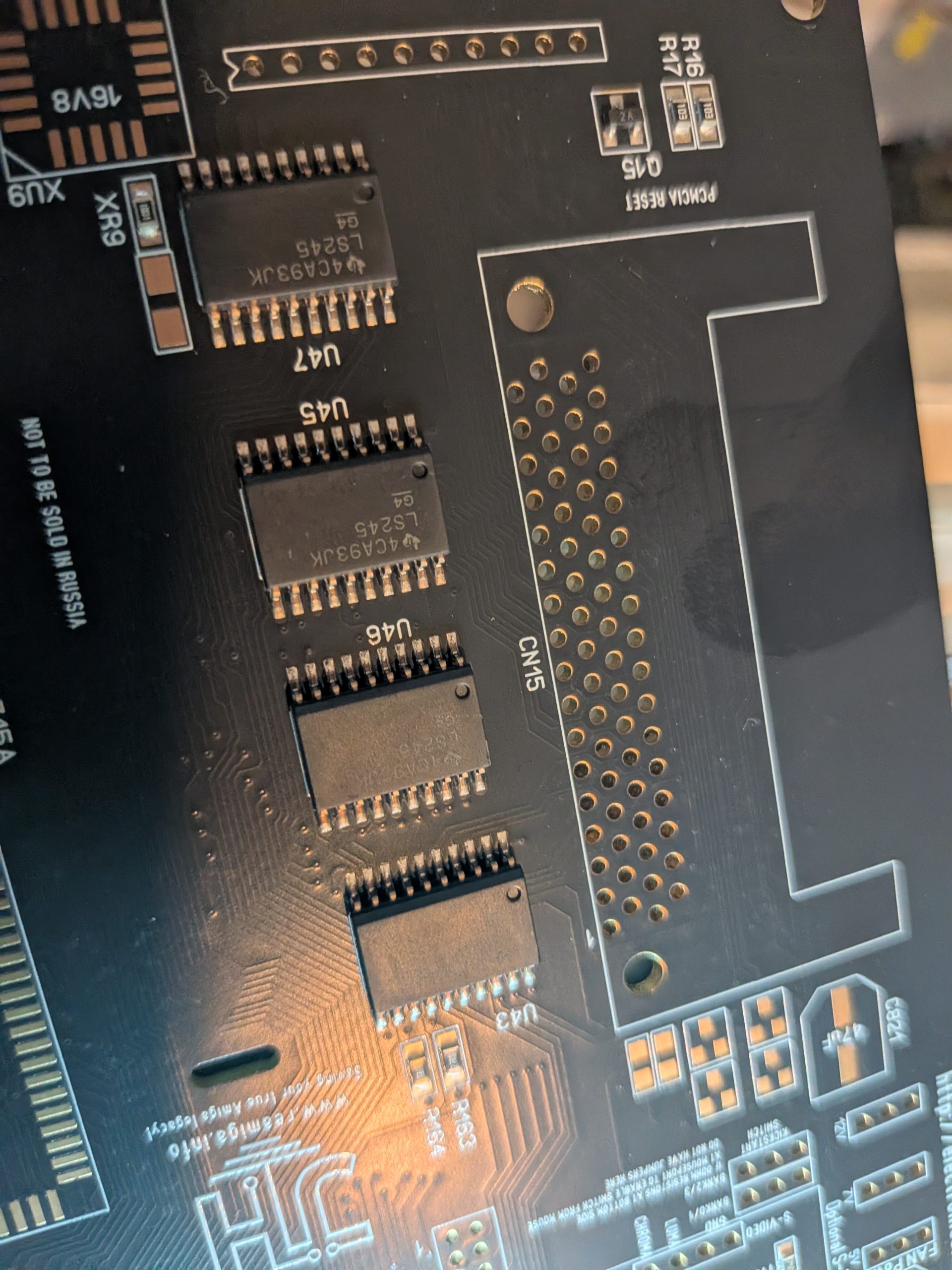
IMPORTANT NOTE about first run of Rev 1.7 there was a slight “oops” with soldermask throughhole headers have too small soldermask.
there is NO issue soldering those thankfully. however you might need more flux and solder on.
this is NOT a PCB House error. it was bad data-files.

Brilliant Chucky. Thanks for improving this great board even more.
If you are going to re a 1200 nake it better 030 on board no pcmcia slot 2 chip and 8 fast on mb cant see the point in re hashing same thing with tweaks
That would be quite a large addon. so no. that is for someone else to do. and the pcmcia is something I use very VERY often so.. that would not be removed