This is my guide how to build the ALICIA.
What is the ALICIA? Well it is simple put an ITX Amiga 1200. For more info of this project read here: https://www.enterlogic.se/?page_id=607
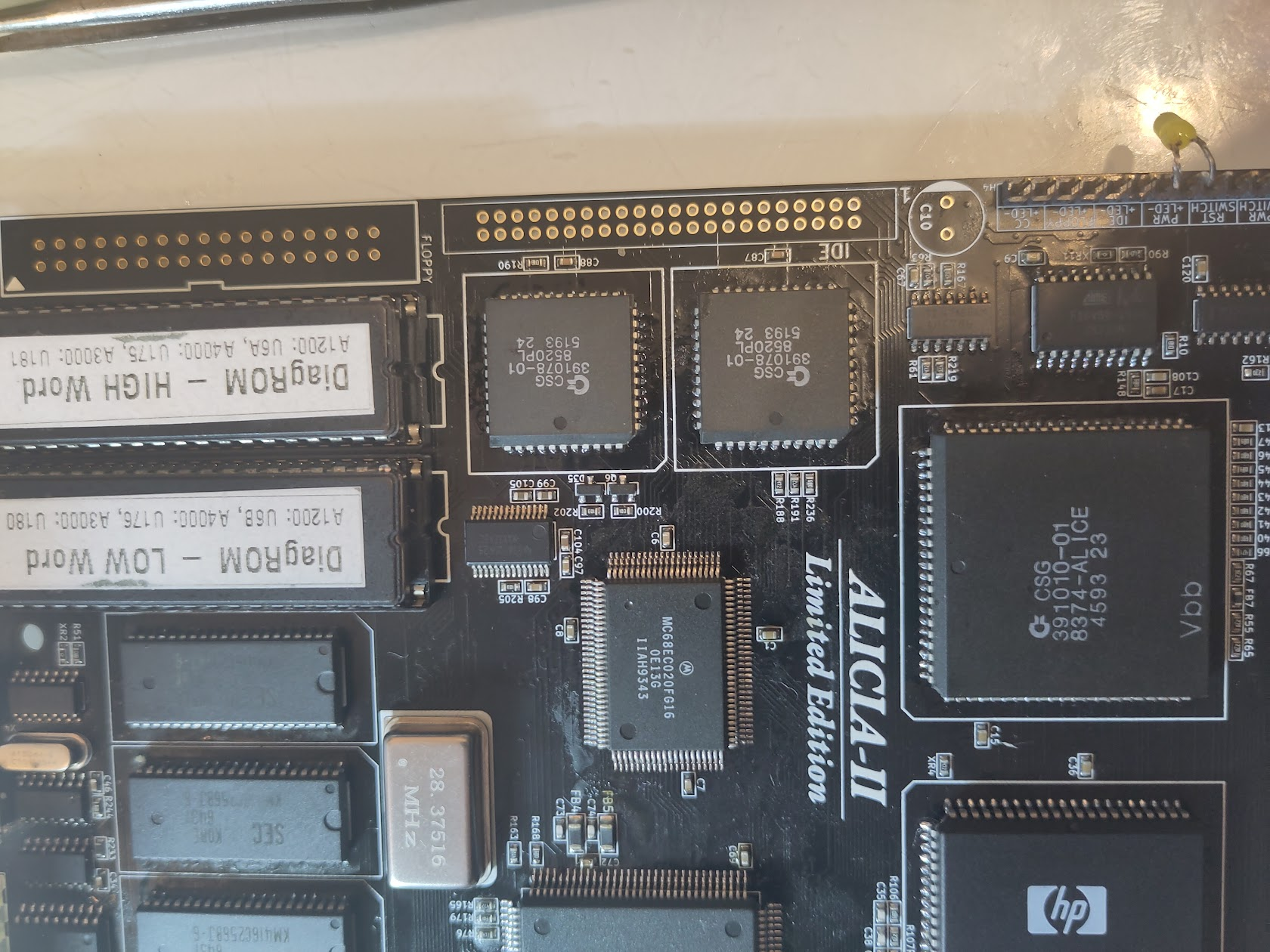
I am building an Alicia-II Limited Edition. but this is more or less same as the “non Limited edition”
This is a quite tight build it is NOT a beginners-project!
I do NOT provide any support of this. and do not ask me too much questions about your build ESPECIALLY if you do not follow this guide. Reason of my way of building it is to have some simple steps and it makes it more easy to find issues while building.
you can find support at: https://discord.gg/3jX9rgjJyd
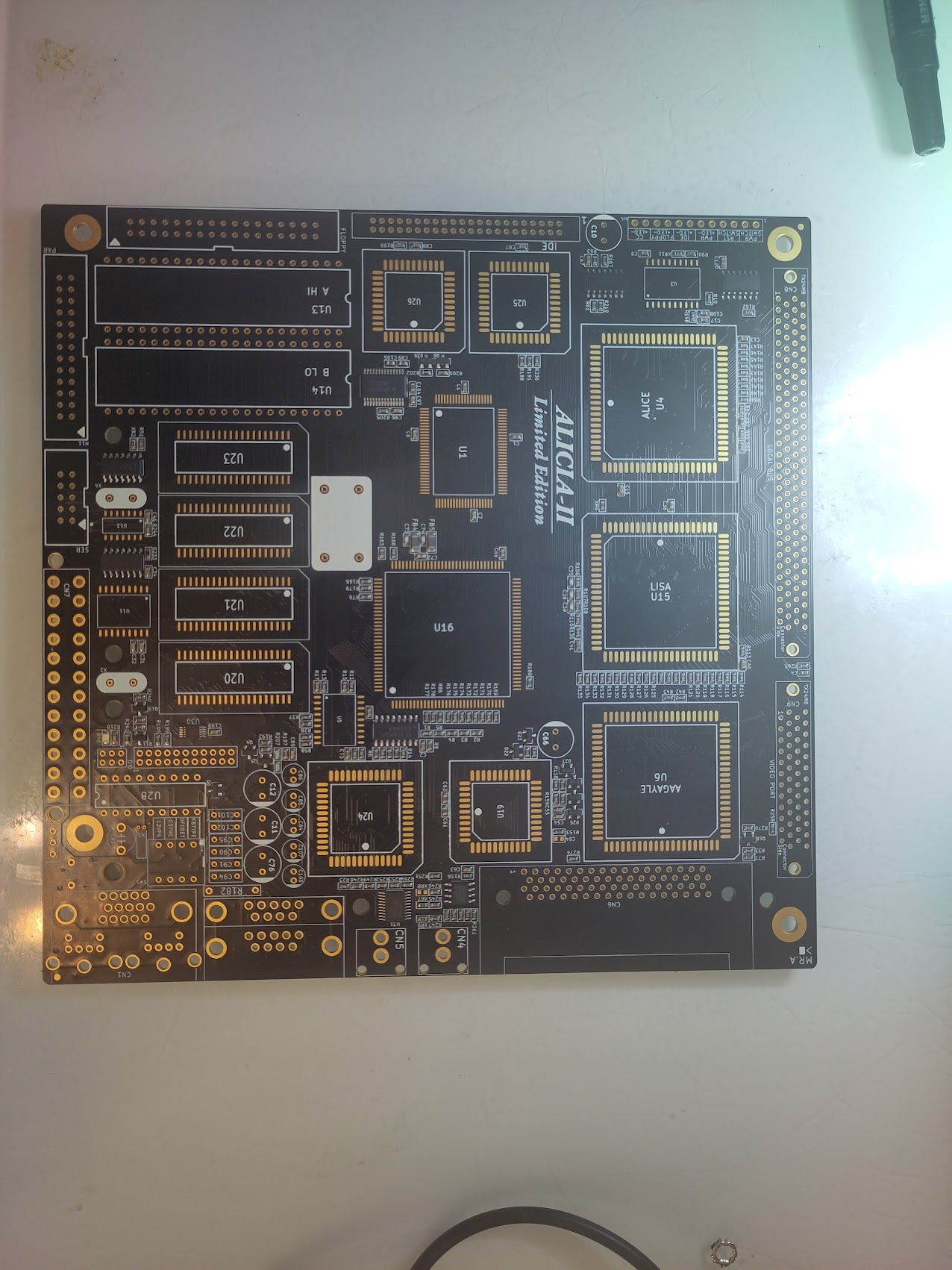
So we start with a board with all passives on.
First step is to get Power handling working.
so add U12 (Attiny), X4 8MHz Oscillator, Power Connector and the Led header.

Now if you short “Pwr Switch” you will see the Led go on! perfect power is working. short it again and it will turn off.
IF you have a non Limited Edition you MIGHT need to add a TC54VC4302ECB713 at the bottom of the PCB located at U8. This handles the reset.
Same with U32 STMAV340TTR it might not be populated.
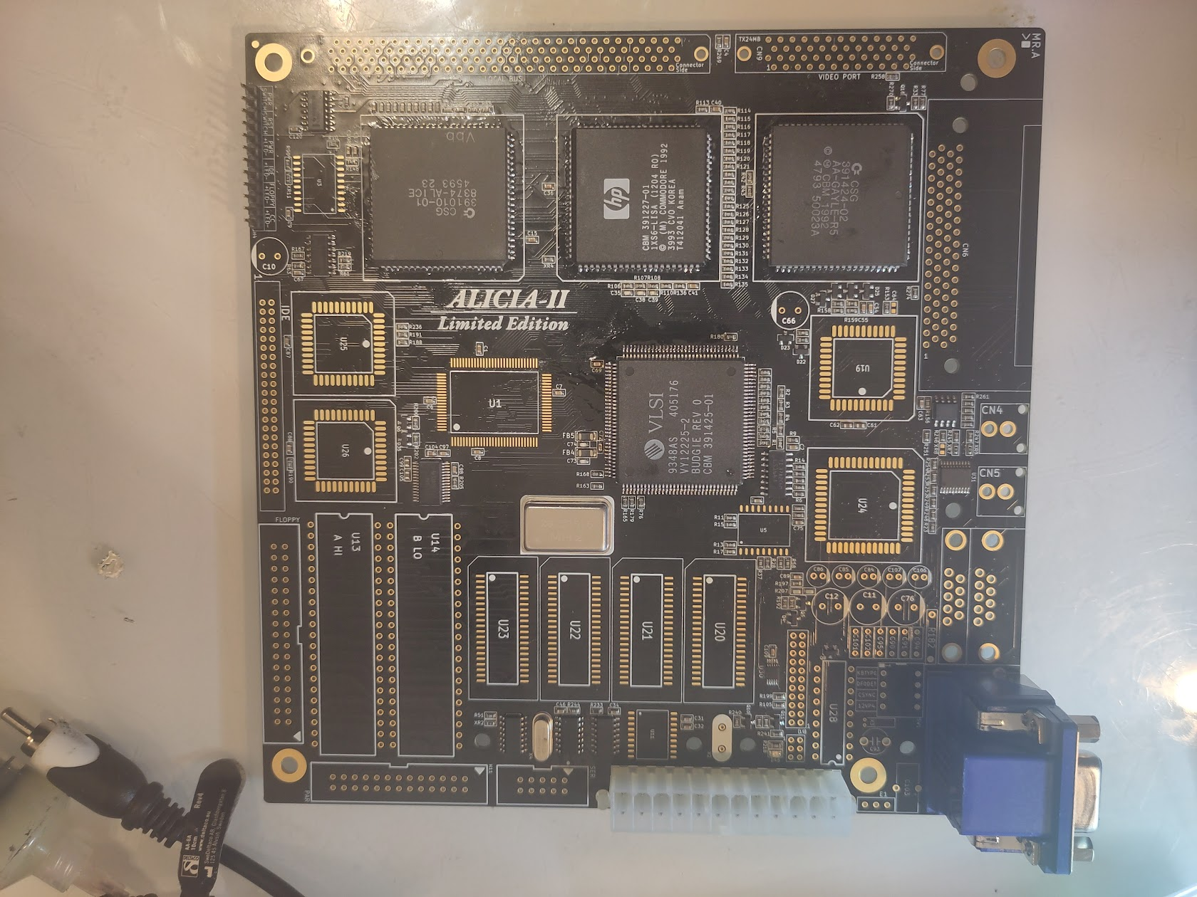
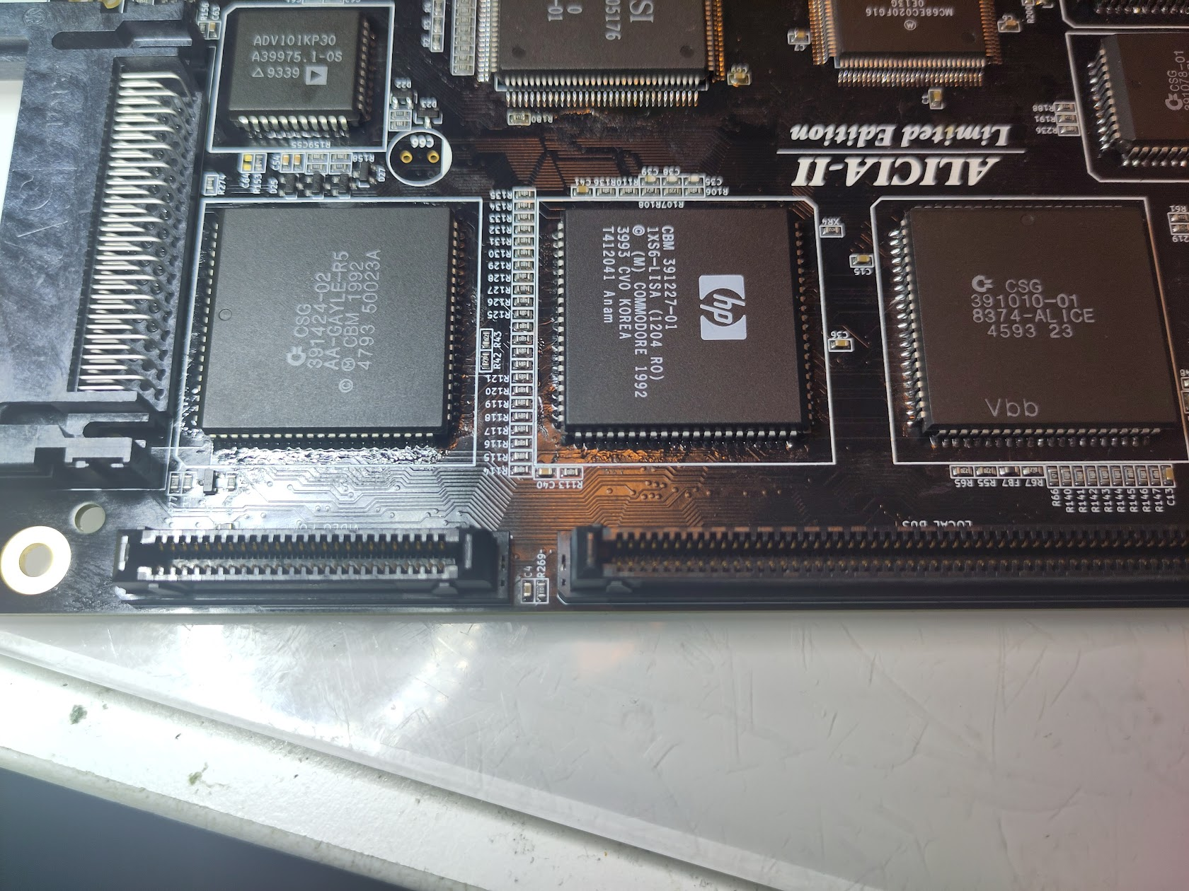
Now to get first step working. the H and V Sync.
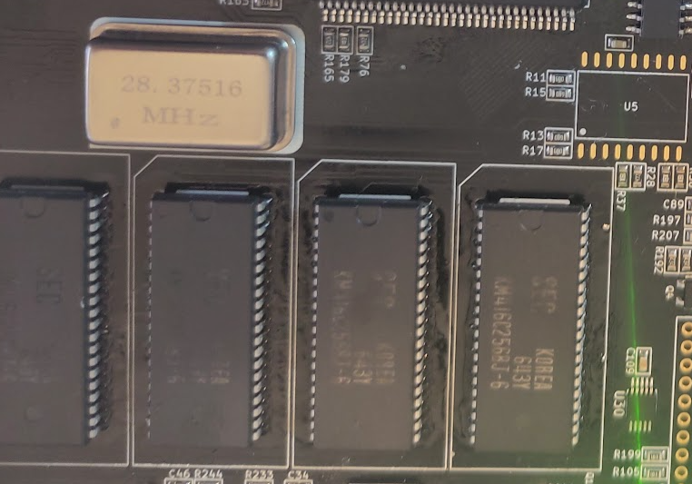
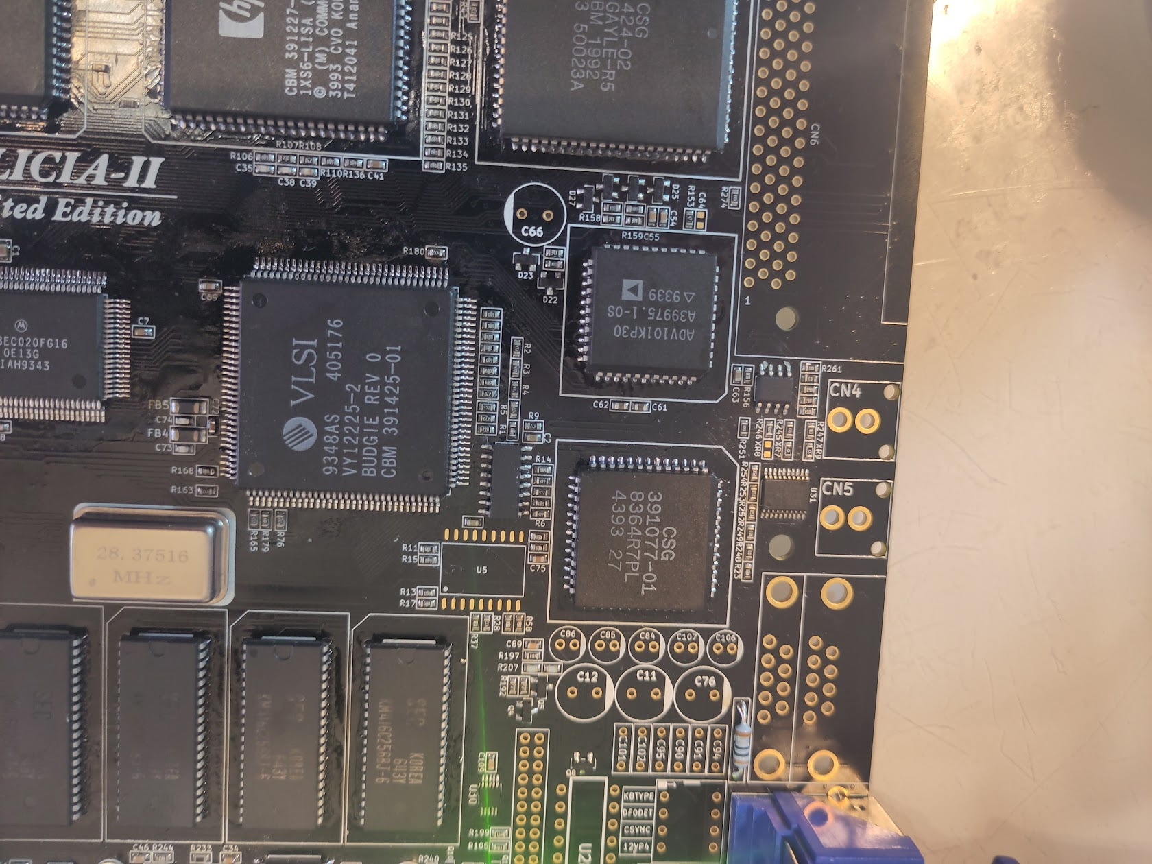
Add the 28MHz oscillator, Budgie, Alice, Lisa, Gayle and the VGA Connector.
AND! as usual! SOCKETS? Sockets are THE main reason people have issues with builds. do NOT use them unless you are 100% sure how to solder them, and if so let the inner frame be left untouched and use NOS Chips (or clean old solder VERY good)
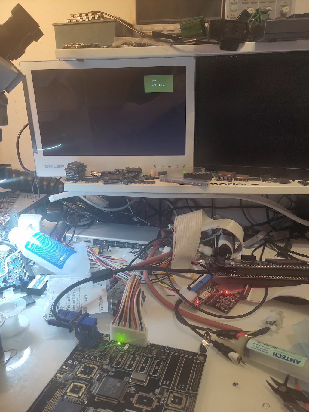
Anyway, Here is everythiing soldered and my Monitor gives a VGA Splashscreen (not all mobitors does this)
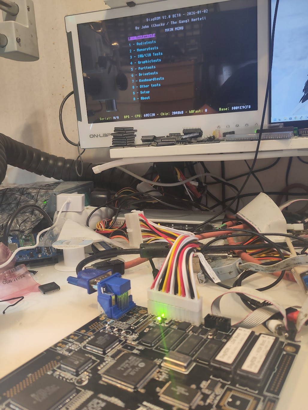
Now it is time to get some instructions running on this baby!.
Add U25 (8520), CPU, U3 (ATF 16V8), ROM Sockets, U11 and the 4MHz Oscillator. Populate with DiagROM
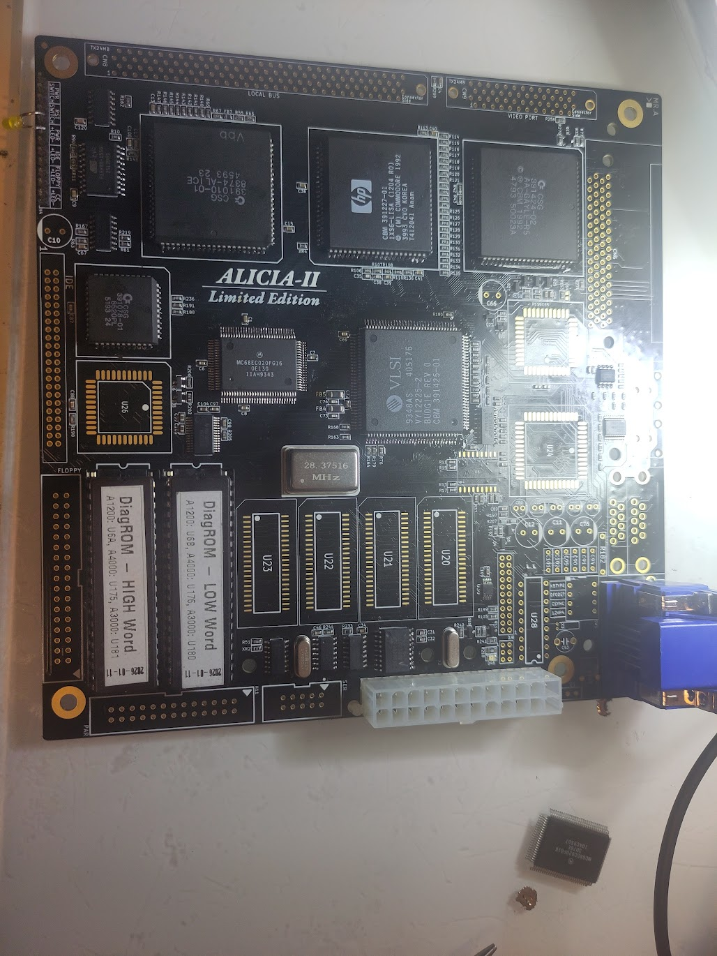
I added a LED on the header, this is to see that the powerled should flash some (atleast change brightness after aprox 1 sec)
Next step is to get Serial communication to work.
Add Paula, 1Ohm resistor (without this. no serial as Paula will not get any power) also add the header to the serialport.
This is a “PC Standard” output. so I connect my PC to it and at power on you should get serial out from DiagROM: (I Want to express a important thing here. Serial output is EXTREMLY important for troubleshooting and I really do NOT recomend anyone continue here without having serial output readable.. get a USB -> Serial adapter if you do not have a serialport on your modern computer)
Perfect, there is output. no RAM found. that is fine!
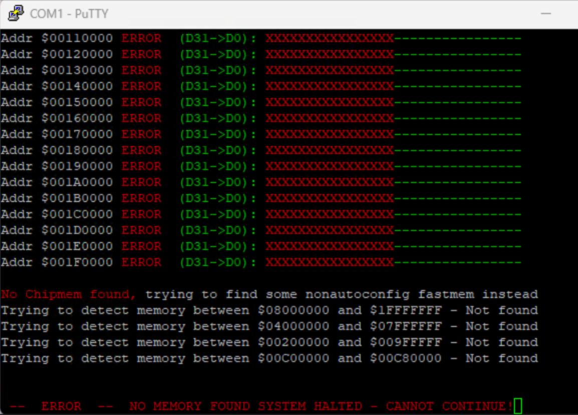
Next step is actually to add RAM. you TECHNICALLY need only to populate U20 and U21 and get 1MB of Chipmem. BUT! as DiagROM stops scanning for ram when it found any ram. I will start populate U22 first. as this is the last MB of chipmem. and when starting DiagROM I will get something like:
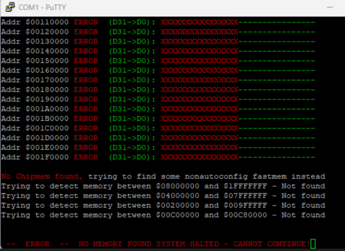
Remember that the green OK part will come at $100000 so do not worry if you have red X in start as that is the first 1MB. so this is output of U22 only! add U23 and you will find 1MB chip at the end.
ok weird. photos lost but..
all chipmem in place and Diagrom shold find it all.
Lets get some output screen
Add the DAC and the non limited version you might need to add LM385DR-1-2 at U17.
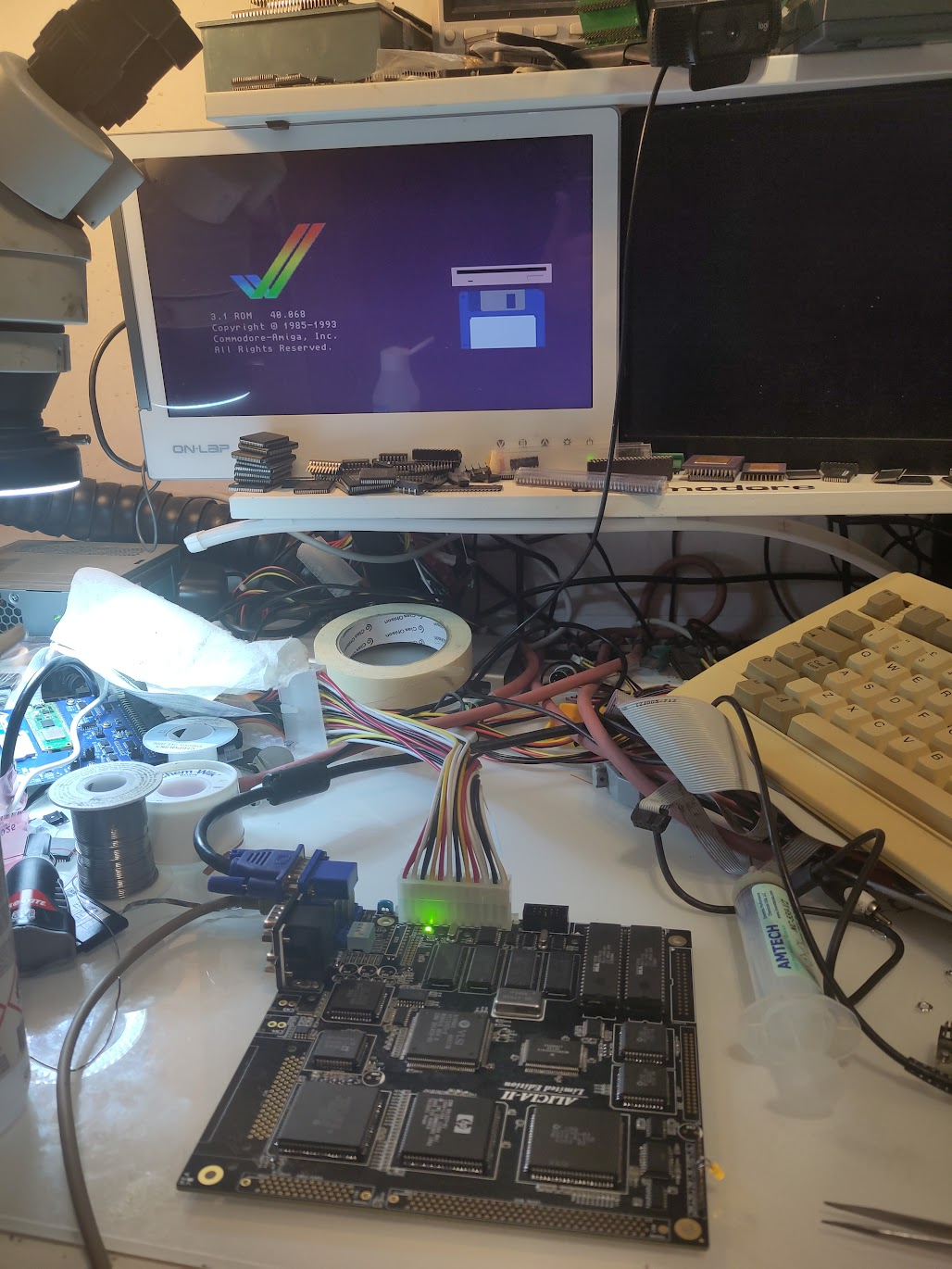
And power on and you should get output:
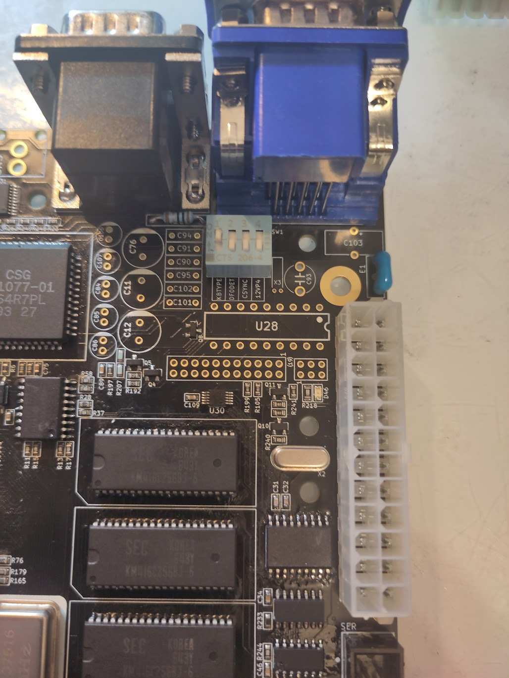
Now add DIP Switch, U5 and the E1 Filter.
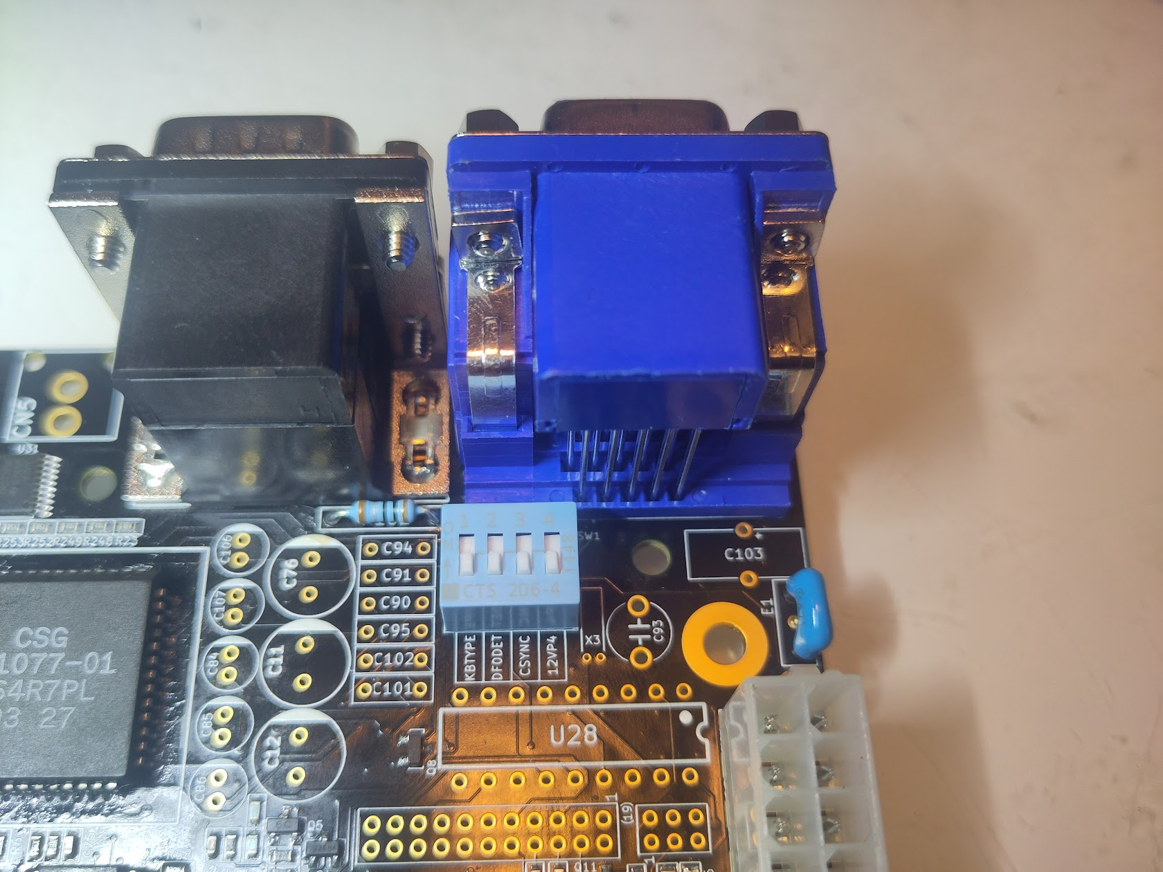
KB Type at this postion (leftmost) will let you use PS/2 Keyboard, in the UP position you will use Amiga keyboard.
Anyway next step is to add the next CIA
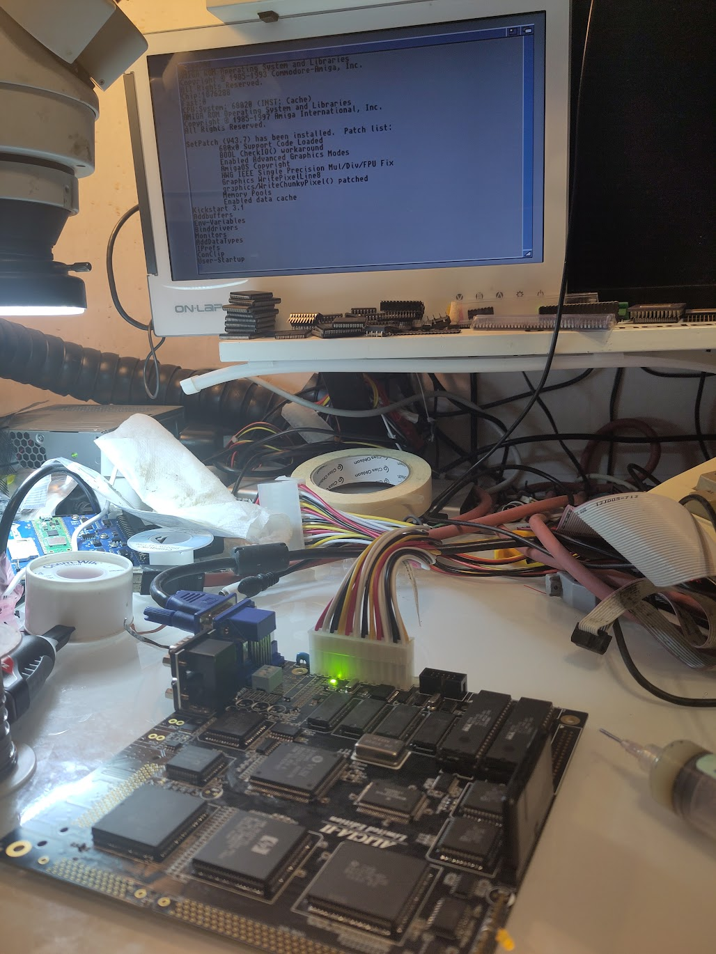
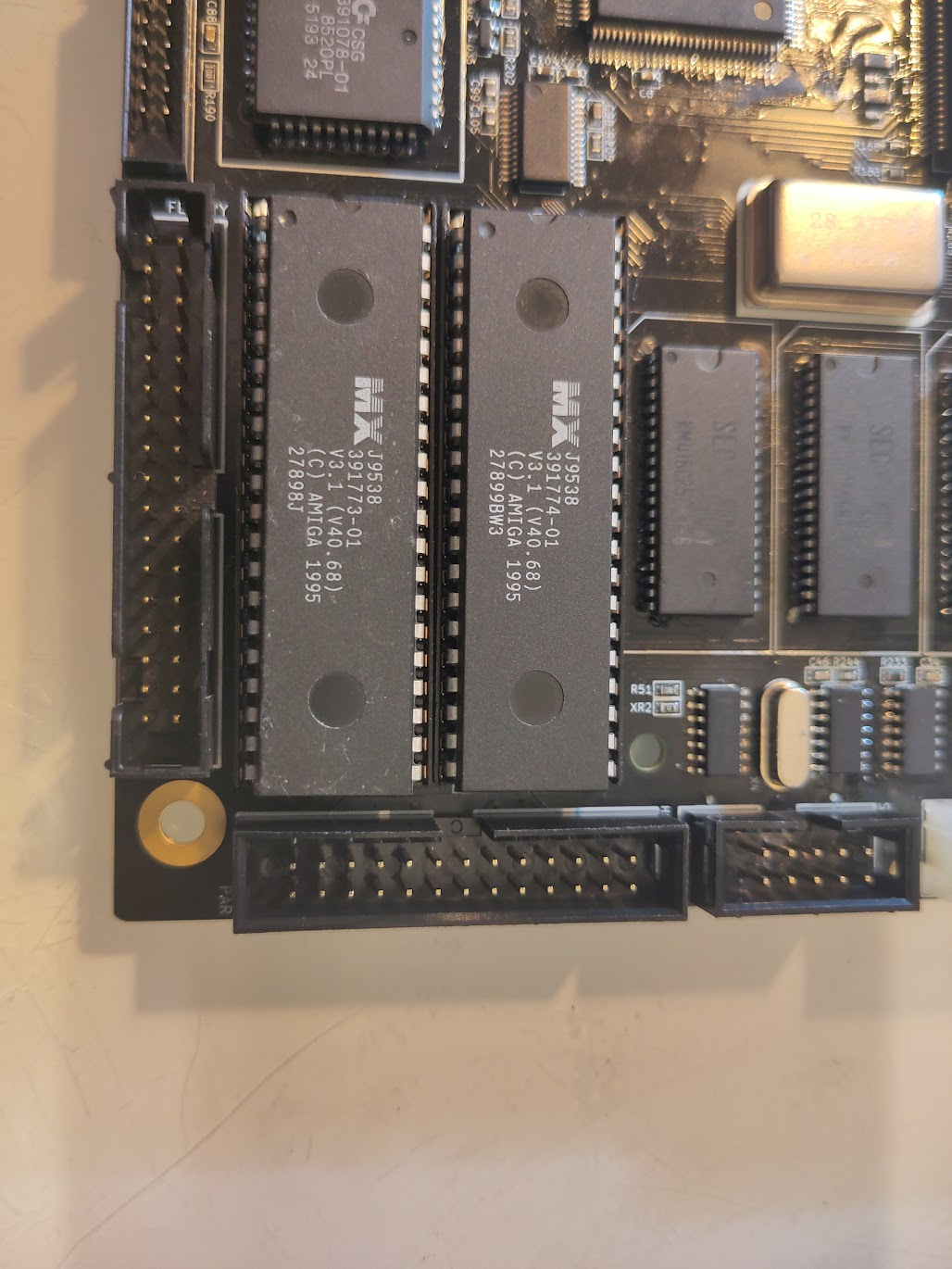
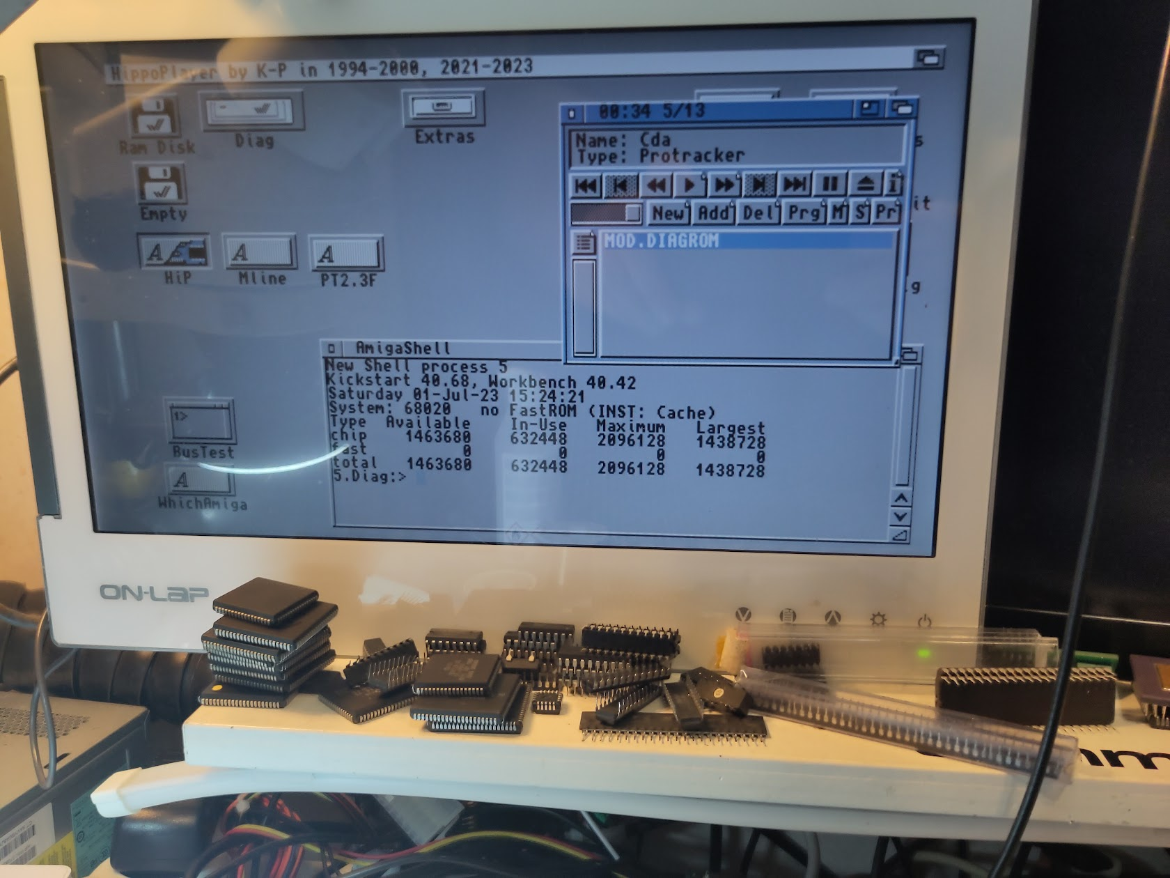
Now if you replace DiagROM with Kickstart you should be able to start Kickstart (remember it can take a while as it tries to find a harddrive etc)
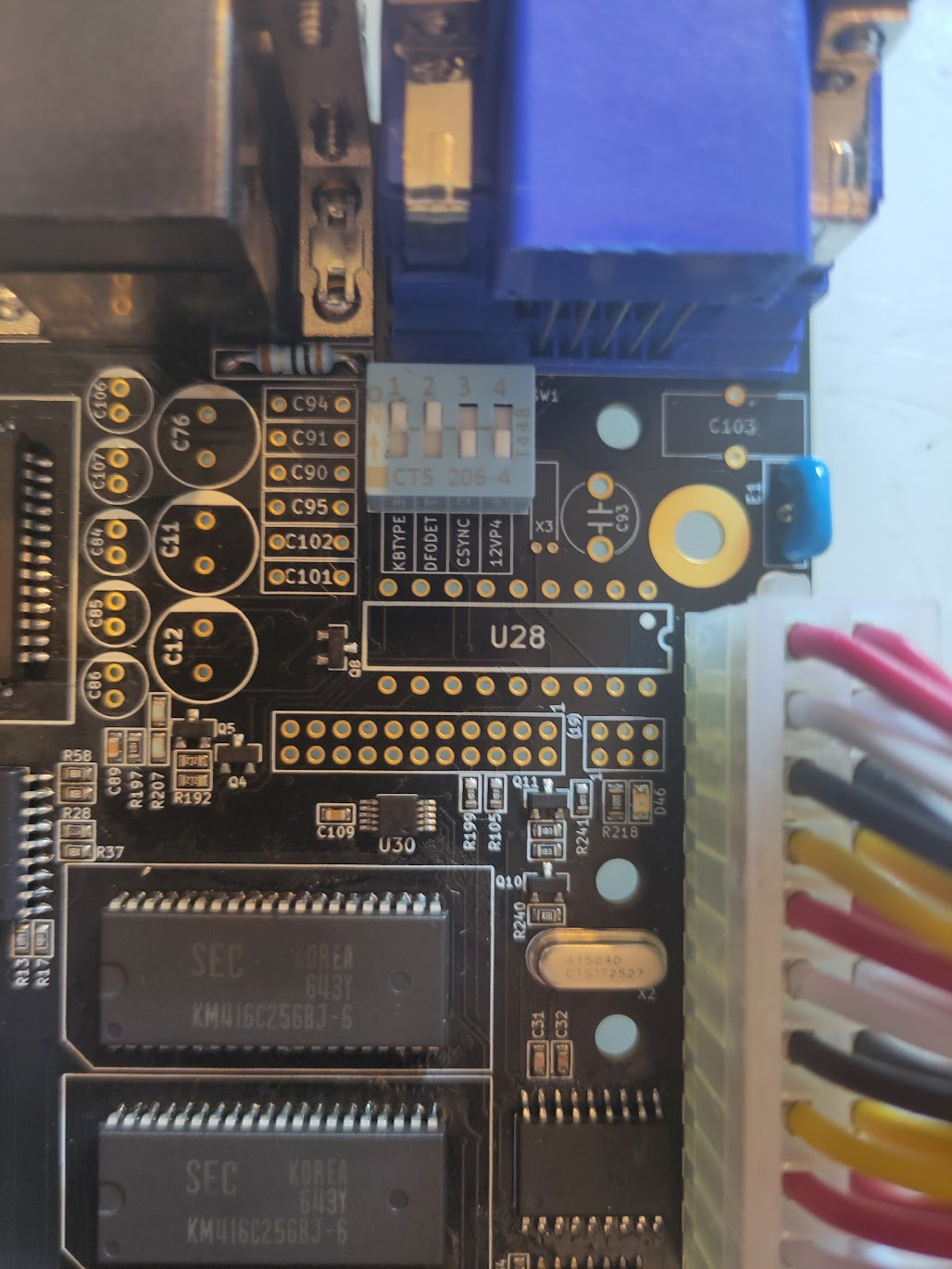
If you set jumper to this position it will detect the floppy different. if you have issues later try this setting.
Now add the HDD Connector and you will be able to boot Workbench:
So time to add floppy and paralell connectors:
also add the PCMCIA Connector:
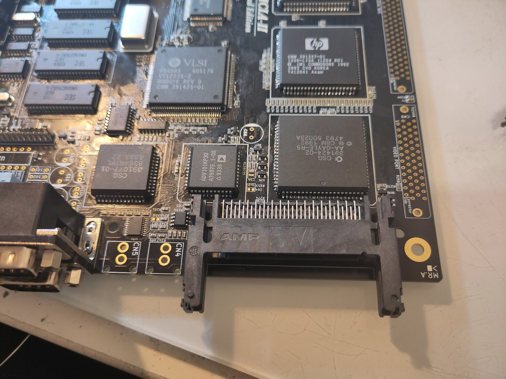
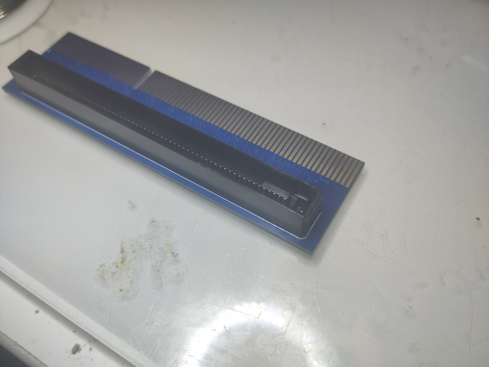
now time for the CPU Slot. this is a.. special one.
If you take a CLOSE look at it. ONE corner have a small notch.
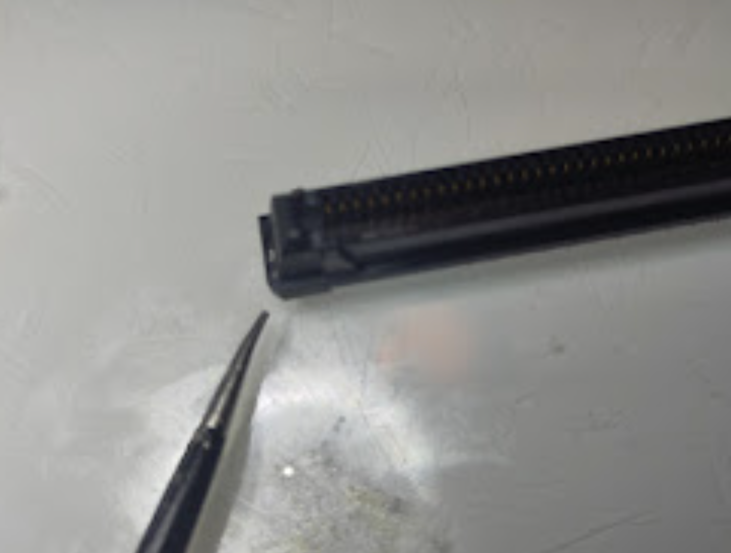
this marks where it should be on the PCB:
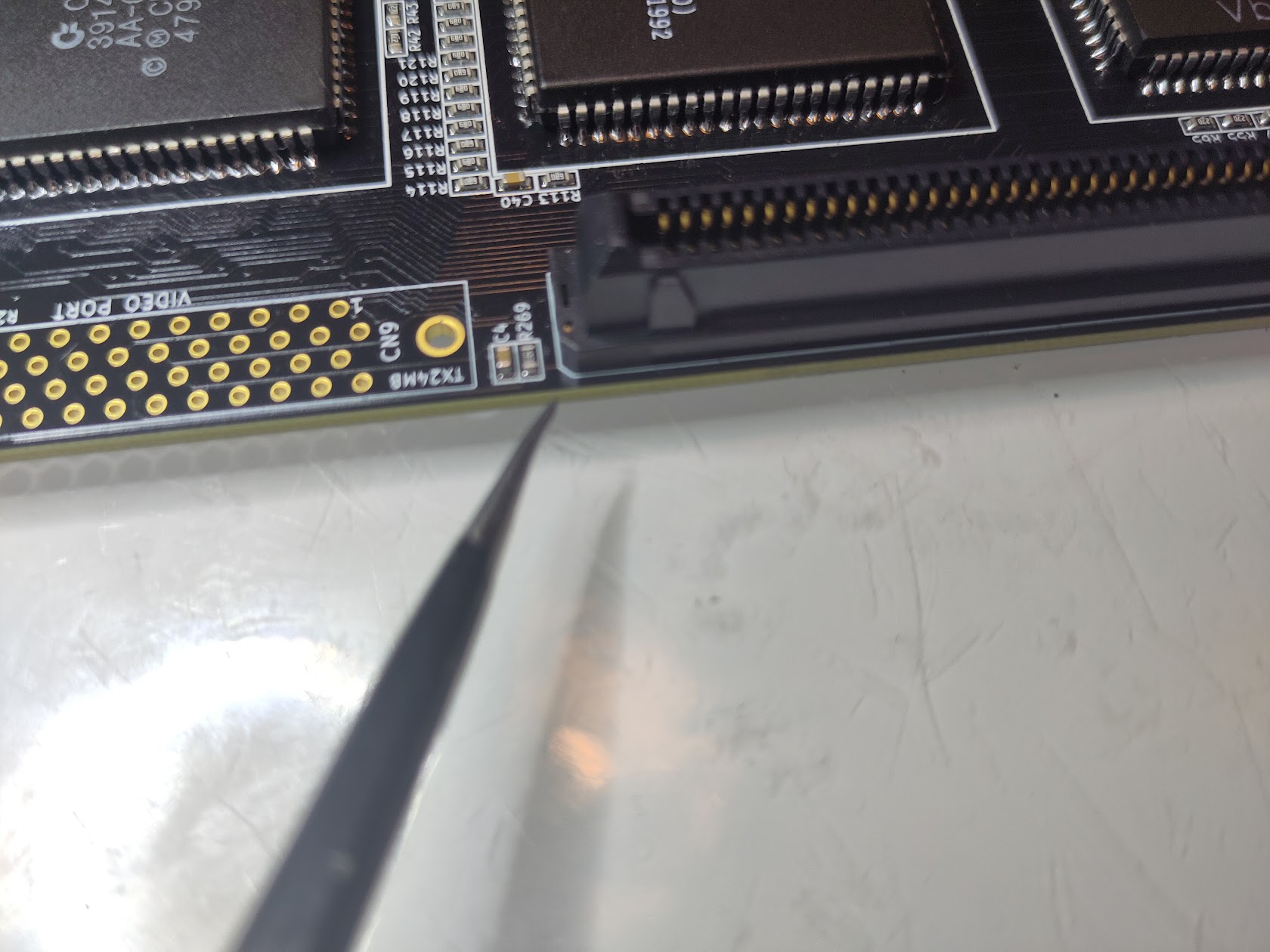
It is VERY easy to turn this the wrong way. but you see on the PCB aswell. that small notch! align this correct! and solder it on.
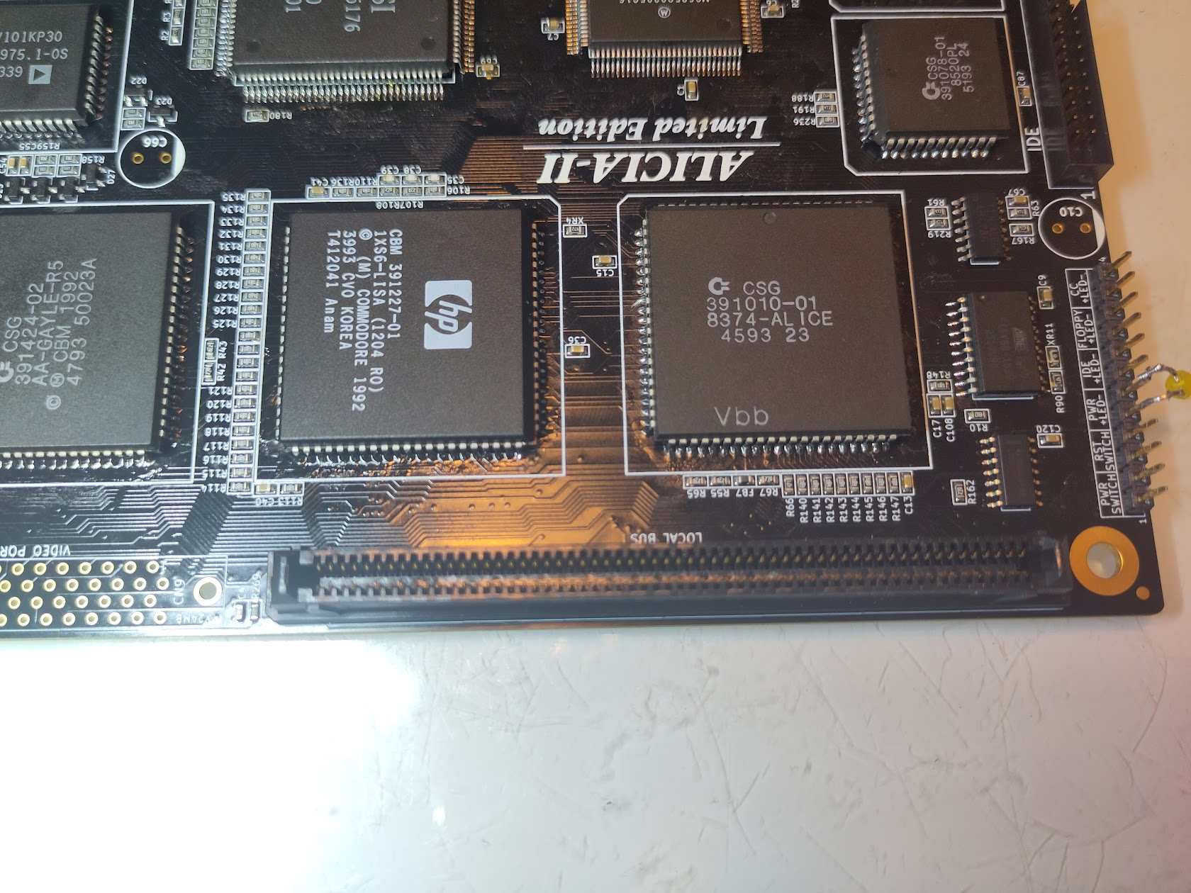
And do the same for the Videoslot:
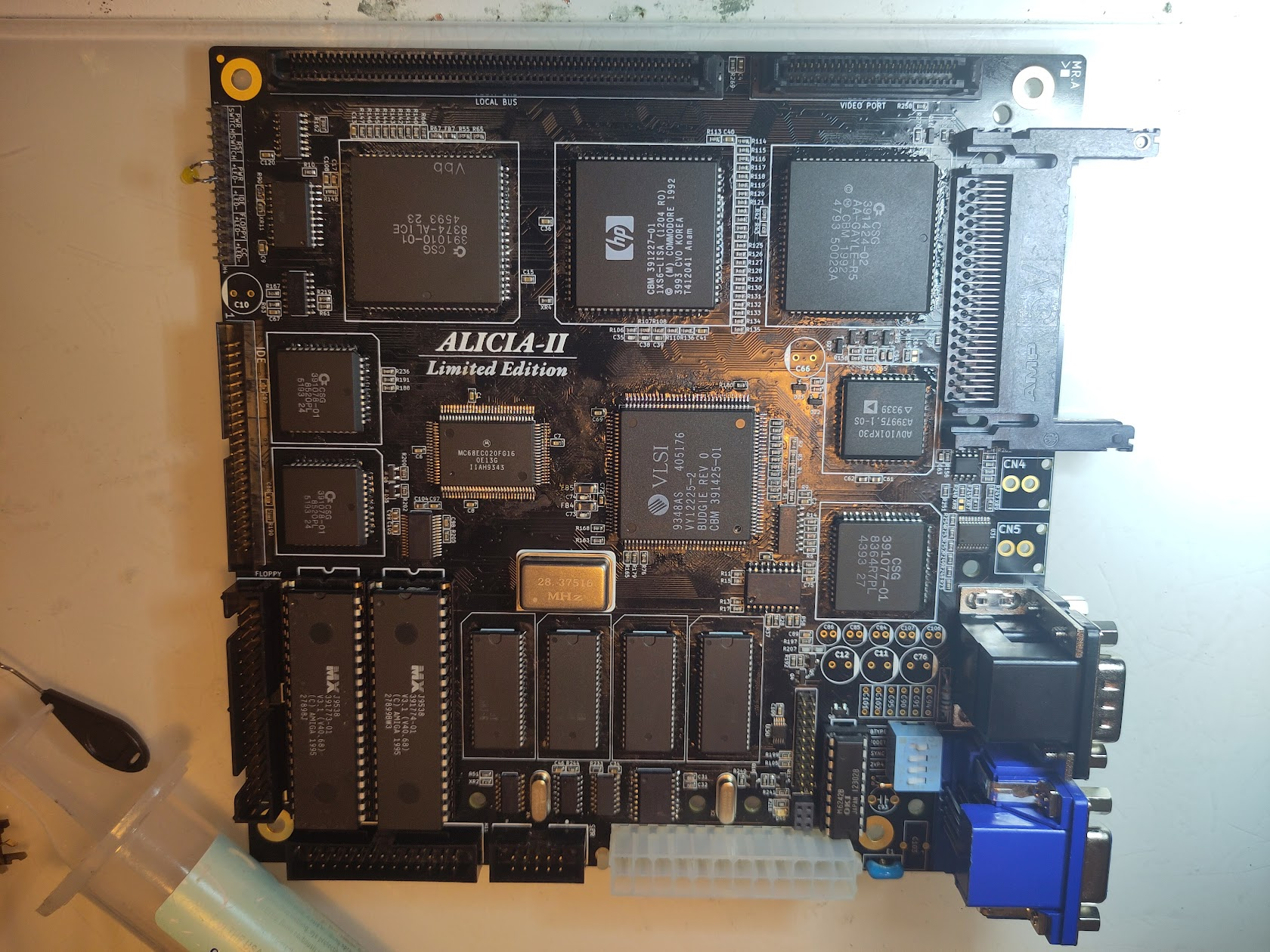
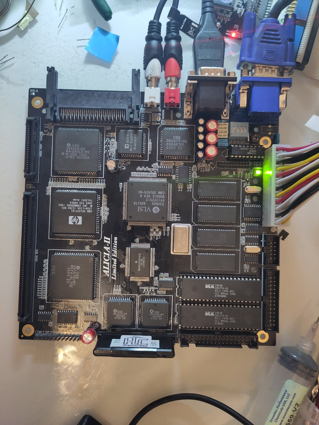
This is all the Glory (YES Audio connectors missing! I got them later during the build 🙂 ):
Also add RTC Chip, and RTC Oscillator.
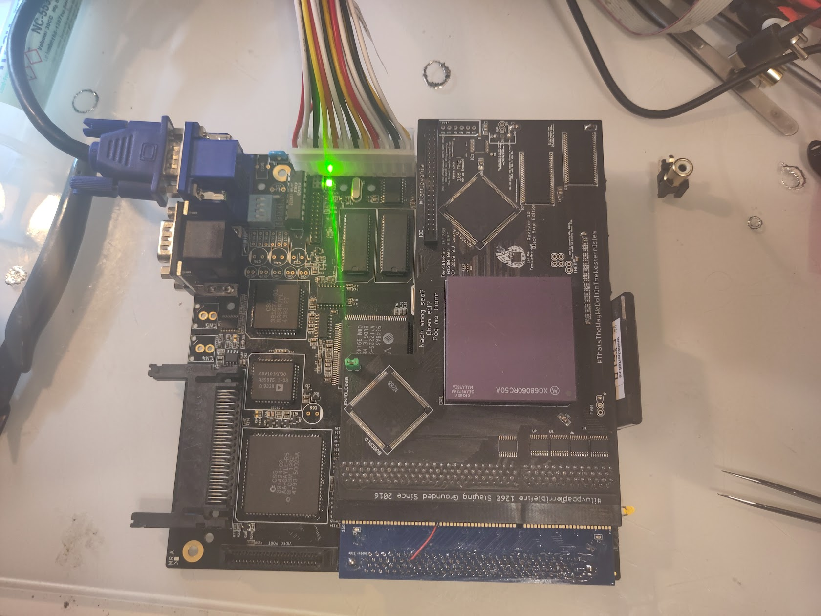
So time for the CPU Slot Adapter:
IF you have a EARLY Version (like I have here) there is a slight error on the PCB:
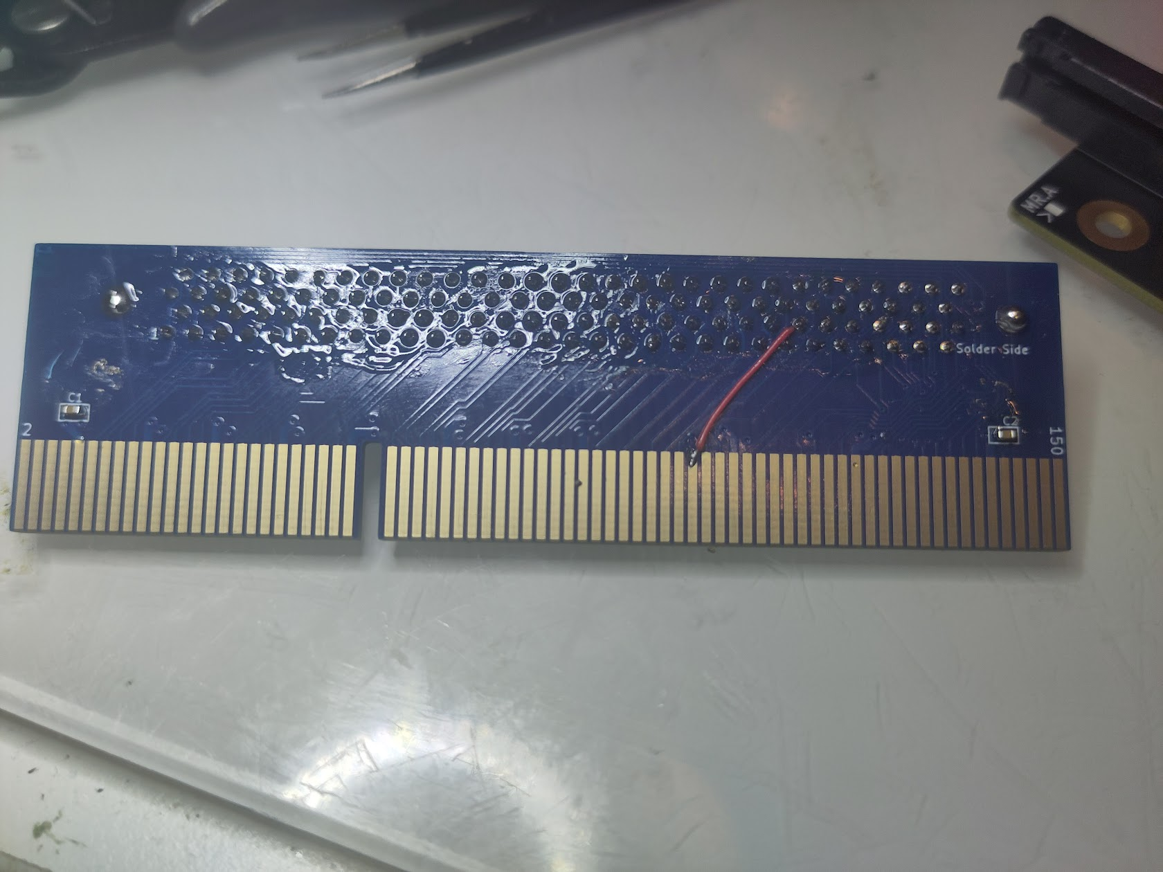
You need to solder a wire like this. this is ONLY on very early boards! without this some CPU Cards will not work.
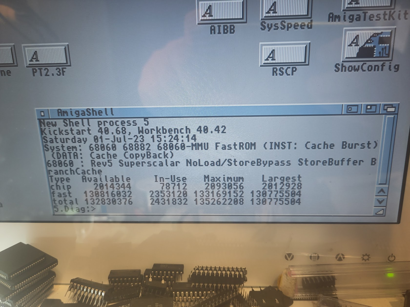
This is a test with a TF1260. Nice with 060 and 128MB of Ram.
Now it is time to solder the Audio, they can be a tight fit but snap them in and solder.
(NO you CANNOT use same RCA connectors as ReAmiga and original Amiga 1200)
Solder the Capacitors (AFTER Cleanup)
6800pF C90, C91, C94, C95
3900pF C101, C102
10uF C86
22uF C84, C85, C106, C107
1000uF C66
470uF C10, C11, C12, C76
RTC Cap Trimmer C93
and one I do not have a picture of but the 100MF Cap for RTC “Battery” C103
(is currently out of stock for me but I want this guide out)
and it is all done! Make sure to add other headers etc, like Clockport etc!
Boot and enjoy:
Chucky This is awesome… Bookmarking this for my build.
Great guide Chucky. At what stage did you solder on U5? I didn’t see it mentioned in the guide.
You also reference Bridgette but I think you mean Budgie 🙂
BUDGIE yah always do that!
however. nice catch U5 was when I did the E1 filter. added in text now