In my next step of buildguides. lets go to the Amiga 4000T.
As always. you need to follow my guide. This is not my project so see this as a “help” of building it. No support-center. and I will for sure NOT help you if you suddenly decided do go outside the guide. like adding extra components. other order or so. but this is “not supported”. I cannot help too much.
Obtaining components etc? well ebay? mouser? digikey? it is up to you to find them.
ok practical stuff done. lets gets started.
Locator links: Amiga 4000T: https://locator.reamiga.info/locator.php?project=A4000T
Amiga 4000T Daughterboards: https://locator.reamiga.info/locator.php?project=A4000T-DBs
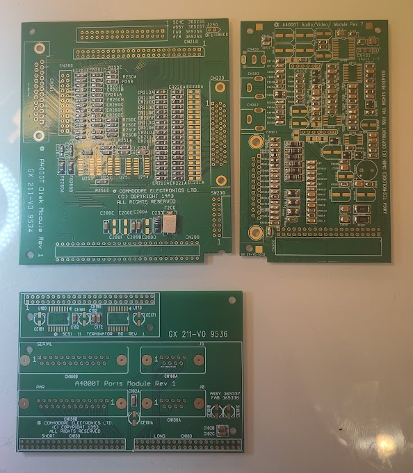
First we start with the Daughterboards, as they will be needed later. better build them.
As usual I start with boards with all passives on (except electrolyticts)
this is quite stright forward. Lets start with the board for connectors. Start with the SCSI Termination part.
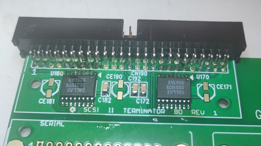
Solder the termination ICs and SCSI Connector.
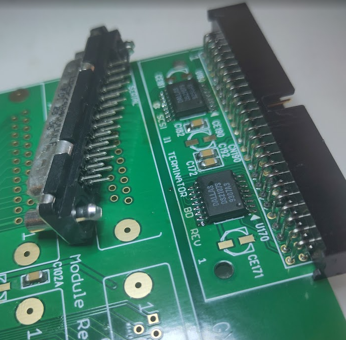
Next the DSUBs.
This is “tricky” as the connectors doesnt really seem to “fit” here. as you can see:
you cannot secure the DUBs through those holes. so what I did is to remove the sides:
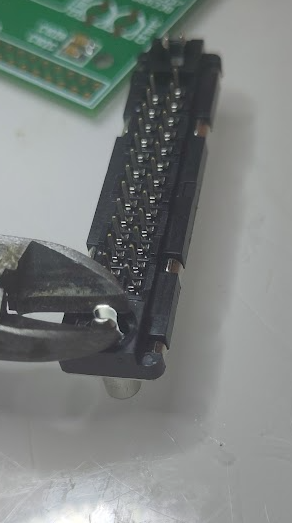
but cutting and bending the sides so it gets off.
then solder the connectors:
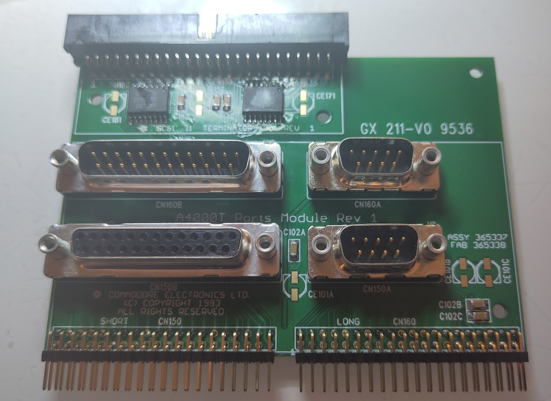
here you see male 25P at top (serial) and female at bottom. also the angeled 40 pin connectors.
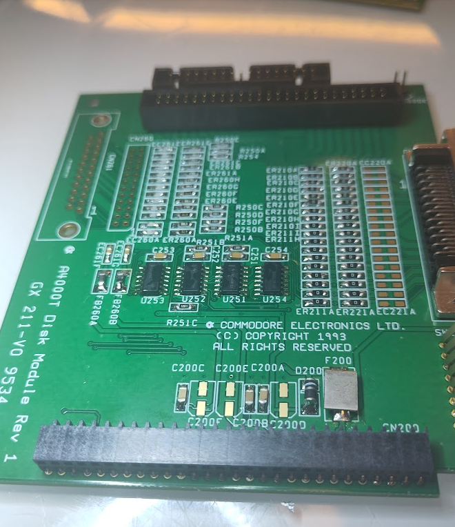
Next is the drive I/O board:
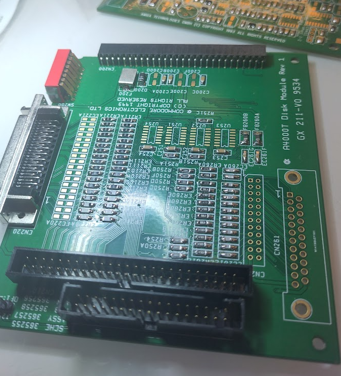
Solder the SCSI connectors internal and external, floppy internal connector and connector to the board.
and the dip switches. next time to solder some ICs:
U253, U254 (74LS125A)
U252 (74LS38)
U251 (74LS74)
And the header for the 880k jumper.
ending up with:
Next the Audio/Videoboard:
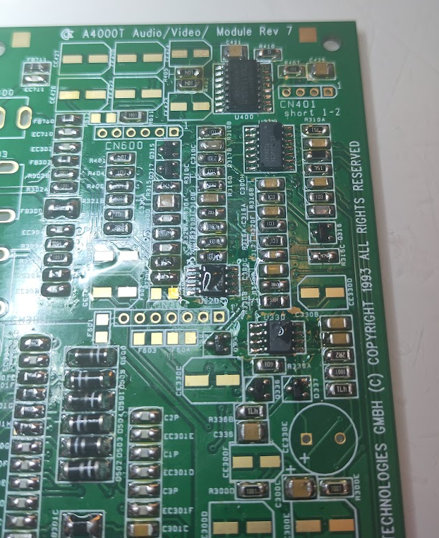
Solder in:
U400 (CXA1263AM)
U310 (LM347)
U320 (LM833)
U330 (KM386)
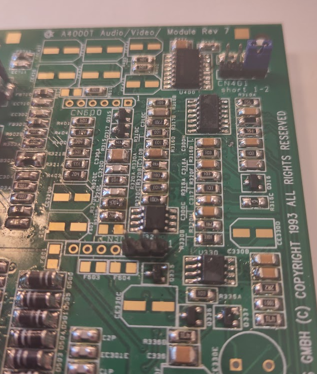
Now add CN401 put a jumper to pin 1-2.
and also a 3 pin header at CB304, this is for CD Audio in etc.
Add RCA Ports, Videoport and optional the 3.5mm headphone jack.
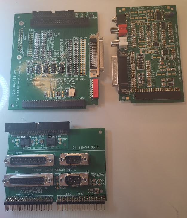
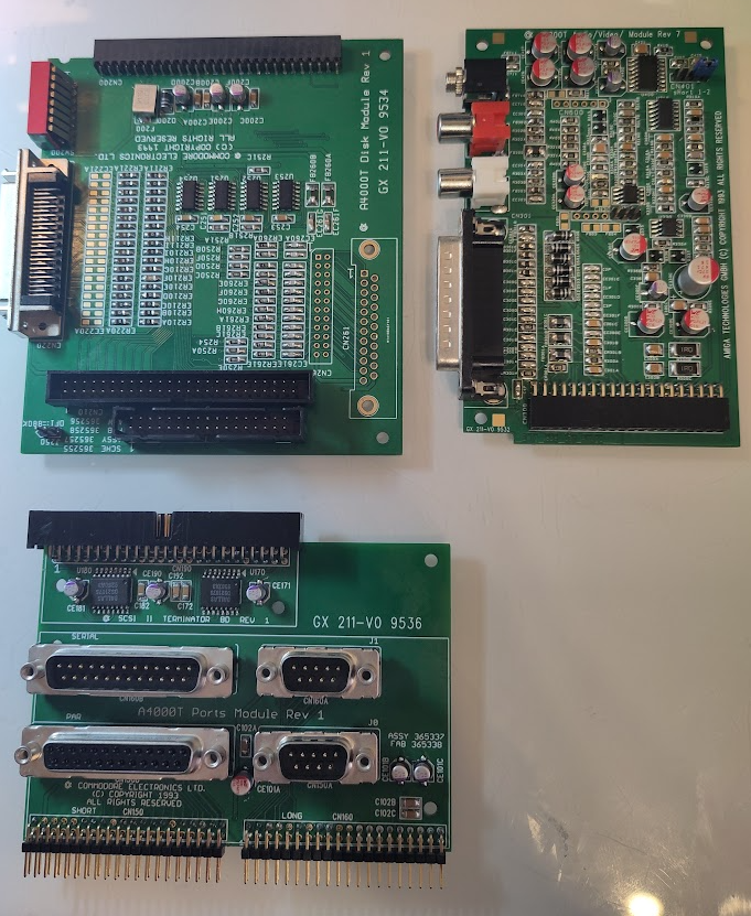
So you now have some boards:
Clean up flux and solder on the electrolytes:
now it is time to make the ribboncables.
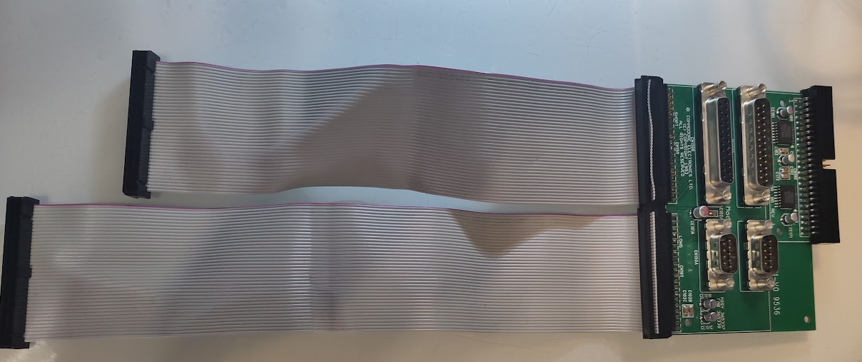
2 40 pin ribboncables. one is aprox 20cm (no idea how much it is in freedom-units)
and the other one slightly longer. like 25cm.
(if you look closly at the 40 pin connectors on the port slot and the motherboard you will see the text “LONG” and “SHORT” this is why. to identify what cable to connect where.

to make the connecors. I have a tool for this. but people can use a vice or so.
you need to google this how to do this..
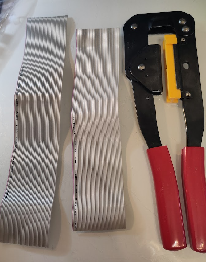
This is my tool however.
on the connector you can see a arrow pointing out pin 1:
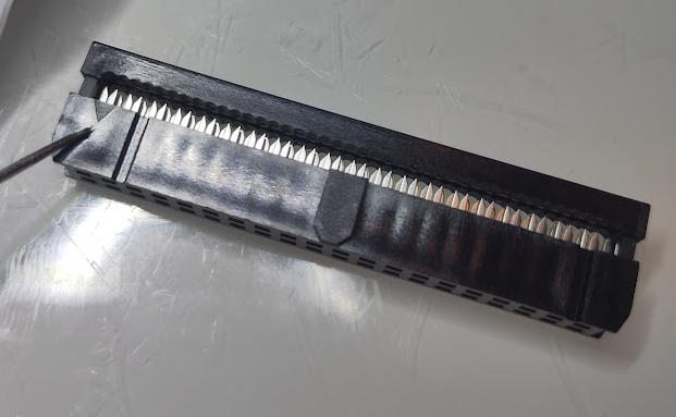
this is where the colored wire will go into.
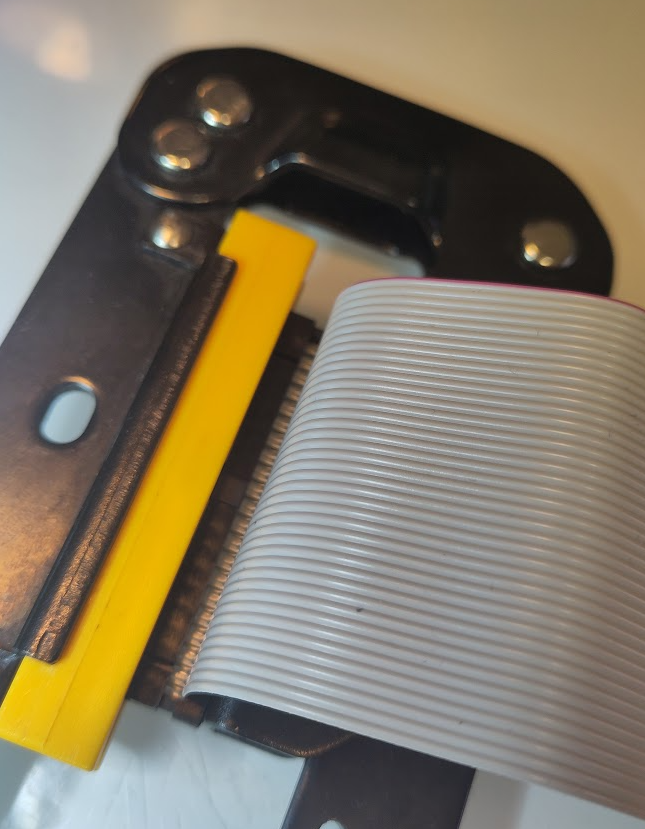
here you can see me having the mark to the upper part of my tool (hard to see. I know) and cable running out of it. and I squeeze and have that part done.
I do a cable like this:
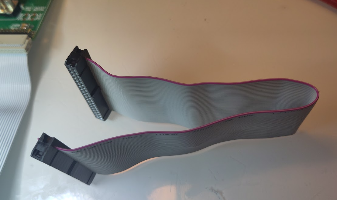
do both the same way.
here you can see it. short cable to “SHORT” and long to “LONG”
a Little note there ARE a “ATX” version of the port connector:
https://gitlab.com/amiga-projects/atx_ports_module
it is outside this scope. but how the 4000T fits in an ATX case I have no idea. but good to know.
Here is the BOM sheet we collectively prepared with erkorh.
https://docs.google.com/spreadsheets/d/1czsNg6O3RXiB12KduvjW-nOGRPwfiWtYTnK7Xi-feMI
Thanx!