Time for part 2.. Unfortunally i screwed up the pictures. so I had to do another board and build it up to get decent step-by-step pictures.
This is the new board:
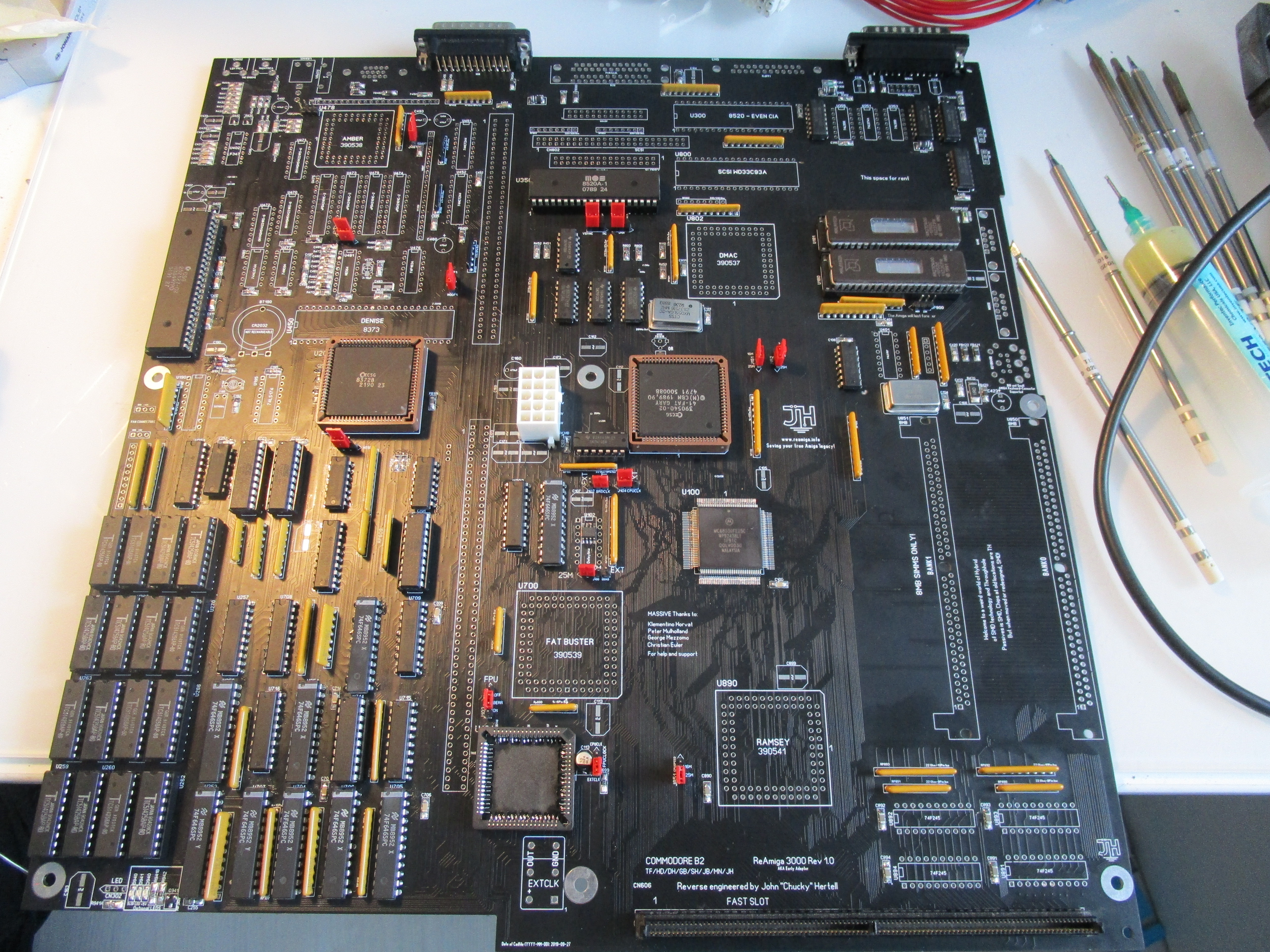
Quite the same. I noticed that in my post I forgot to tell that I also have populated U702 (74F256) and U703 (74F646) those are not needed for chipmem to work, but add them anyway.
This is now a system that can start DiagROM via serialport.
Time to get something on the display.
so we add Denise, U451 (74HCT244), U452 (74HCT244) and the Vidiot at HY450, text facing to the Amber socket.
Now you will get something on the RGB port. (NOT the VGA one! that is for Part 3)
Anyway.. next step is to get some fastmem.
You need to populate Ramsey, U891, U892, U893 and U894 (all 74F245) and the simmsockets.
there is a “whoopsie” here, the holes for the simmsocket plastic-rods are missaligned so you will need to cut the plastic on the simms.
Put in 8MB simms, first in bank 0 then in bank 1.
now we have fastmem.

it is time to be able to control DiagROM and not just run and see.
of you looked on pictures you will see that U305 (1489) is already populated but I never mentioned it. so if you haven’t done it, put it there now. now you can receive data on the serialport aswell.
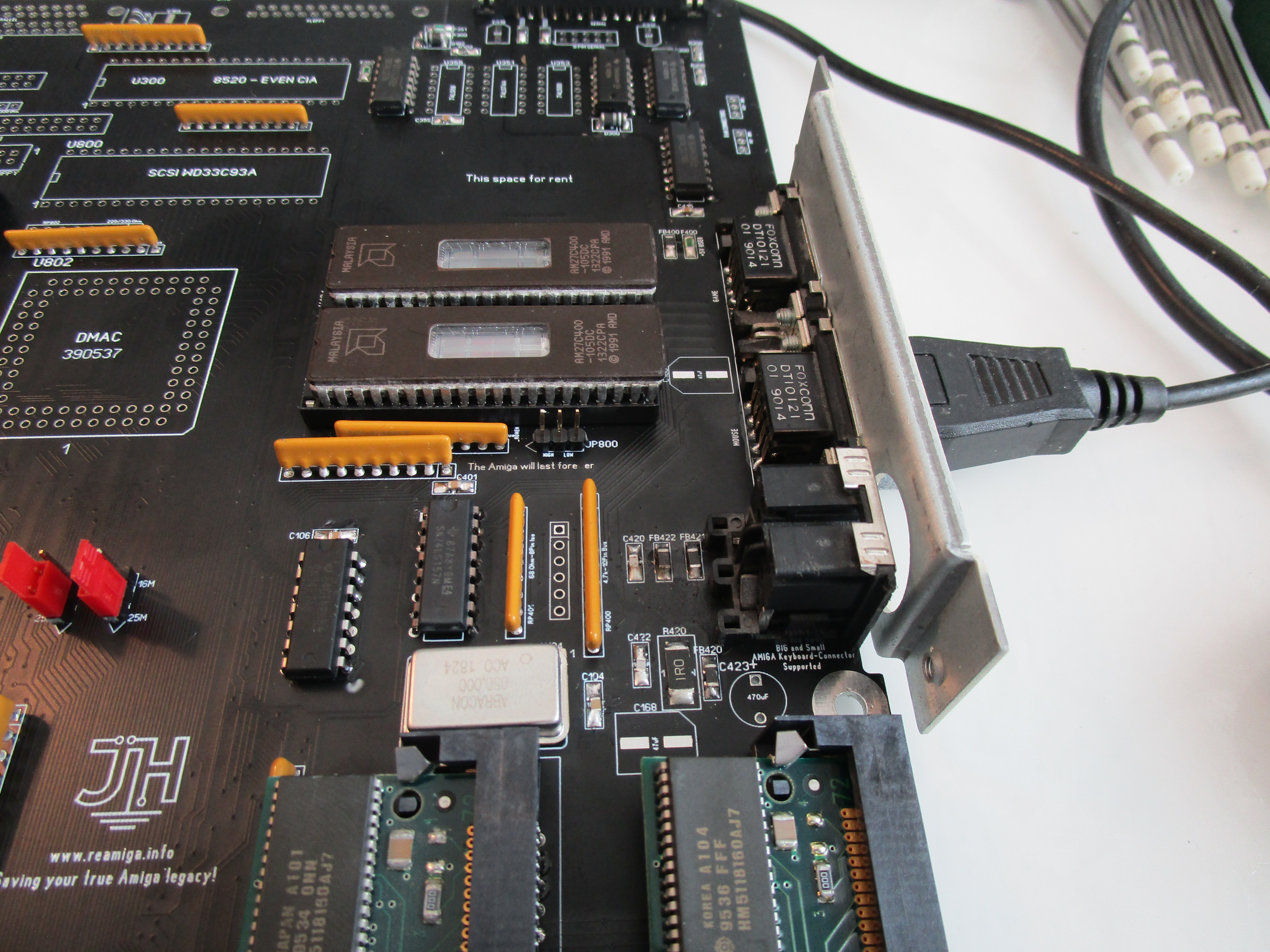
also add keyboardconnector, the 2 9pin Dsubs and populate U401 (74LS157):
Now you can control diagrom aswell.
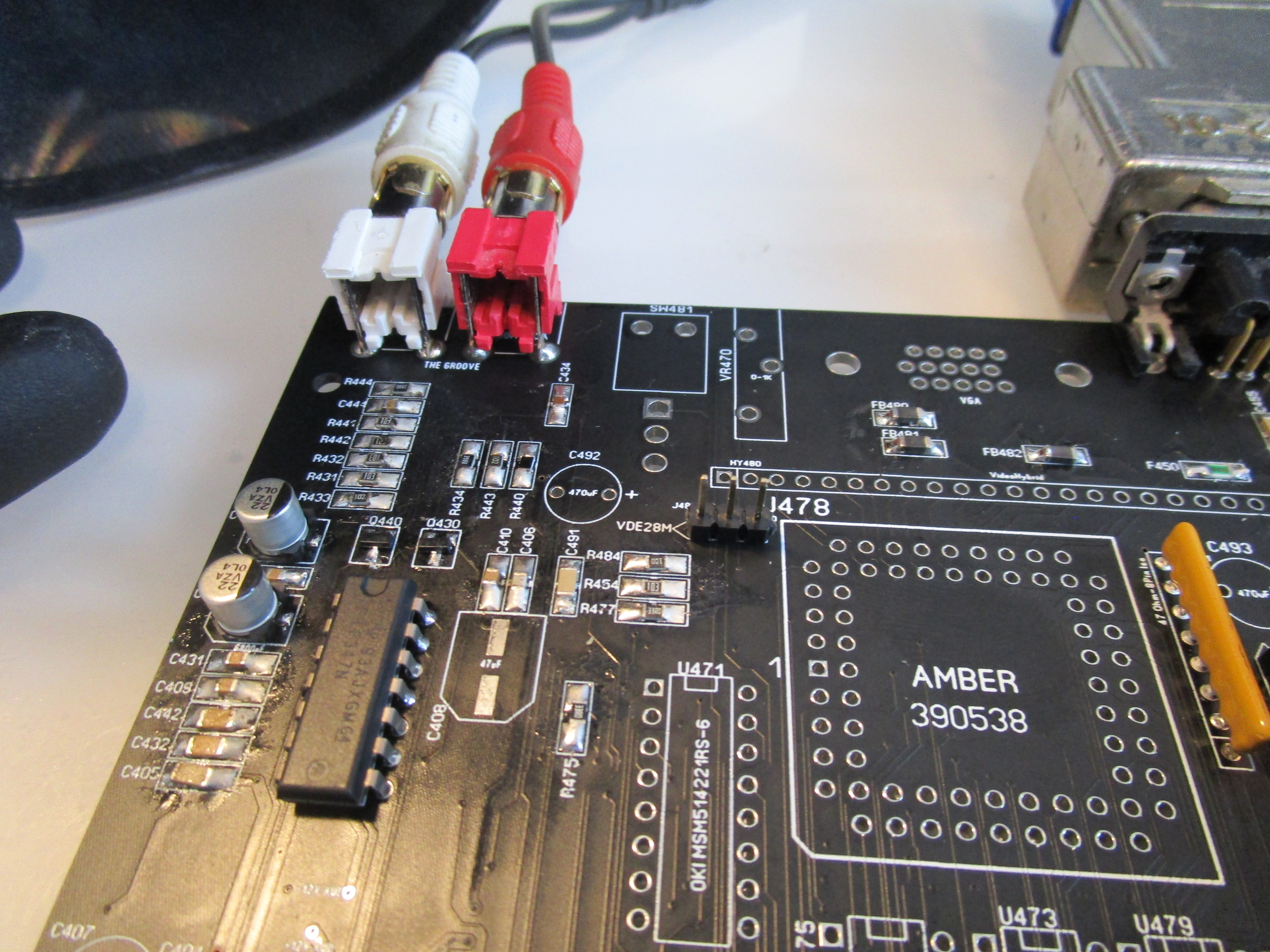
Next step is audio…
Populate U402 (LF347) and put in the RCA Plugs. and to get Audio you need to populate C433 and C443 with 22uF capacitors) (and NO.. do NOT use ceramic caps where it should be electrolytes, they behave different and is voltagedependent so they have different capacitance at different voltages etc.. I will NOT help you if you put in tantals, ceramic or shit like that)
Anyway. now we have audio.
Time to get stuff for the floppy.
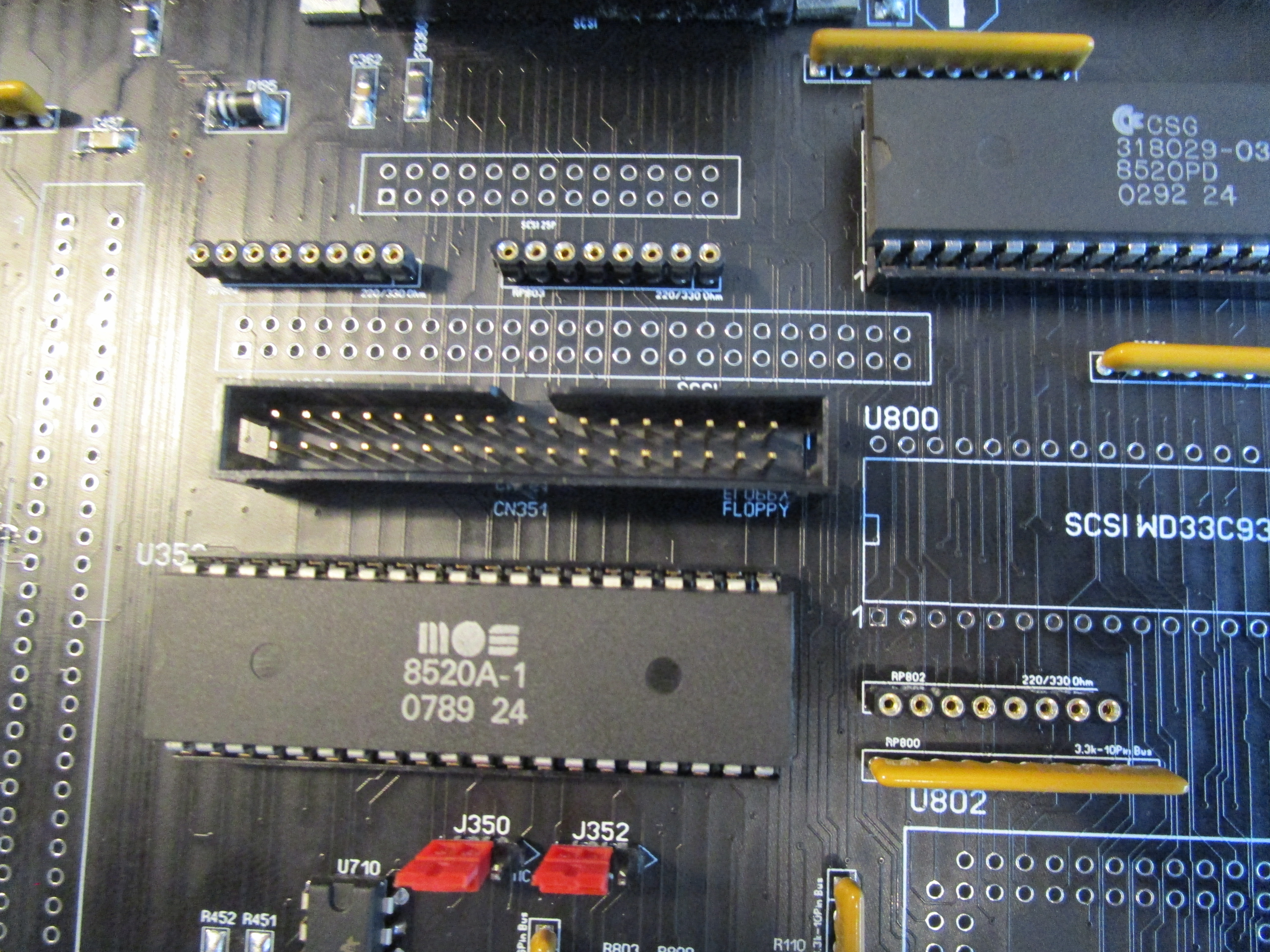
Populate U353 (74LS00), U351 (74LS74), U355 (74LS08) and the Even CIA, also put in the external floppy conector and the 32pin IDC for the internal floppy, and we got floppy working:

Now put in the SCSI/Parallel connector:

Parallel port will now work.
Time for SCSI. remember the resistorpacks I told you not to populate. put in a female header for them here so you have a socket for the Terminationresistors:
now a sidenote about SCSI amd SCSI termination.
a SCSI chain must be terminated at Start and End of the cable, nothing more, nothing less.
so on the SCSI cable internally, the device on the outer end (physical, not ID number) should have termination, no other device. and if you do not have a external device, you need termination on the motherboard (those headers you just put in).. if you have external units, you should not have termination on the motherboard. See the whole chain as ONE cable and the motherboard is in the middle!..
so : <External cable> – <Motherboard> – <Internal cable> one termination at each end.
so as we will not use a external cable. put in the resistors in those headers. the dot (pin 1) facing to right here on picture.
So now add the SCSI Chip, DMAC and the 50 pin SCSI IDC:
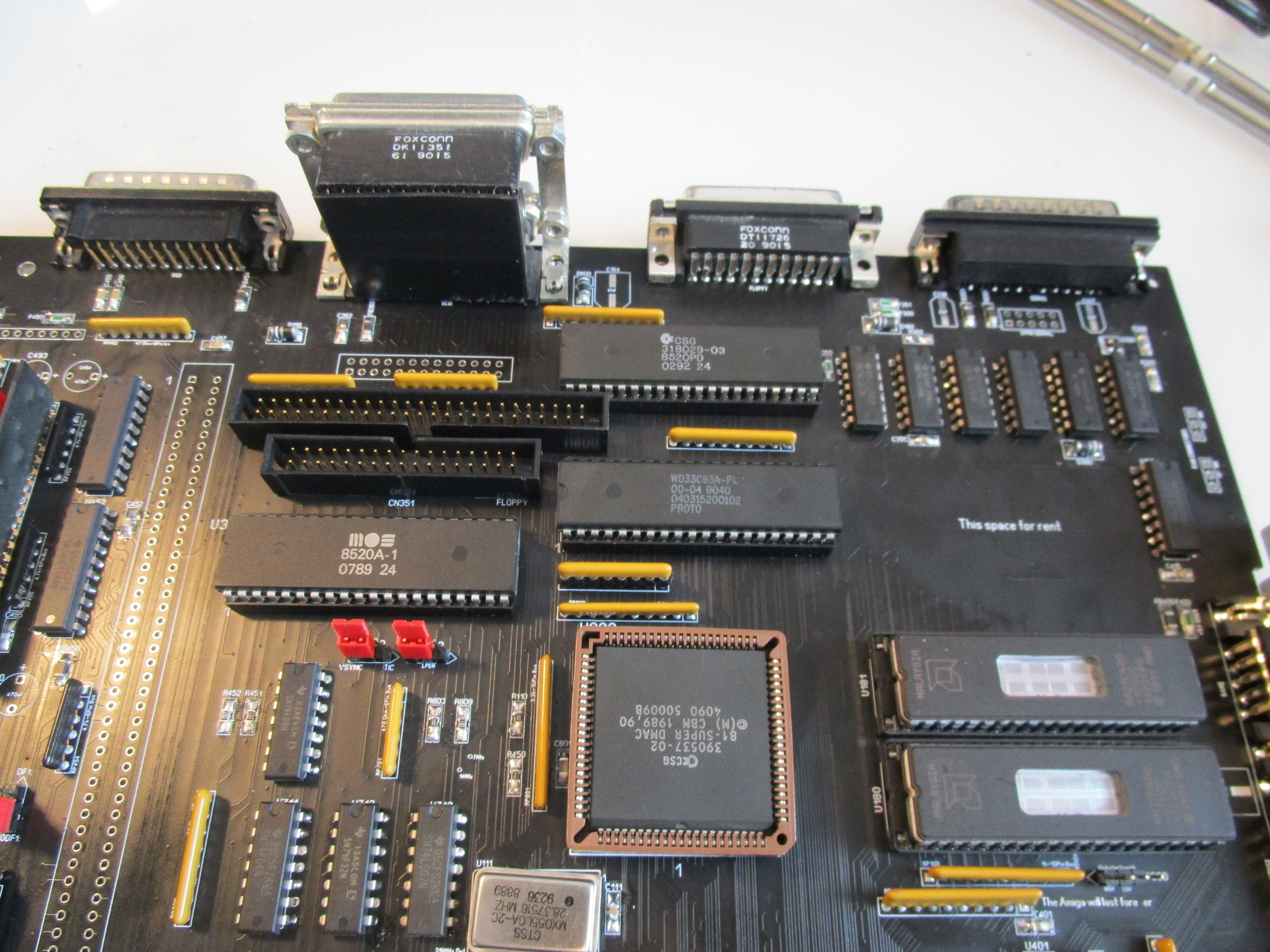
You shold now have workig SCSI (DiagROM sadly have no DiagROM test at the moment)
Time for some Zorro:
Add Buster and before you add the Zorro DB connector: as the area is tight, put in caps: C169, C173,C171, C175 it is WAY more easy now. And solder in the Zorro DB Connectors:

Almost there.
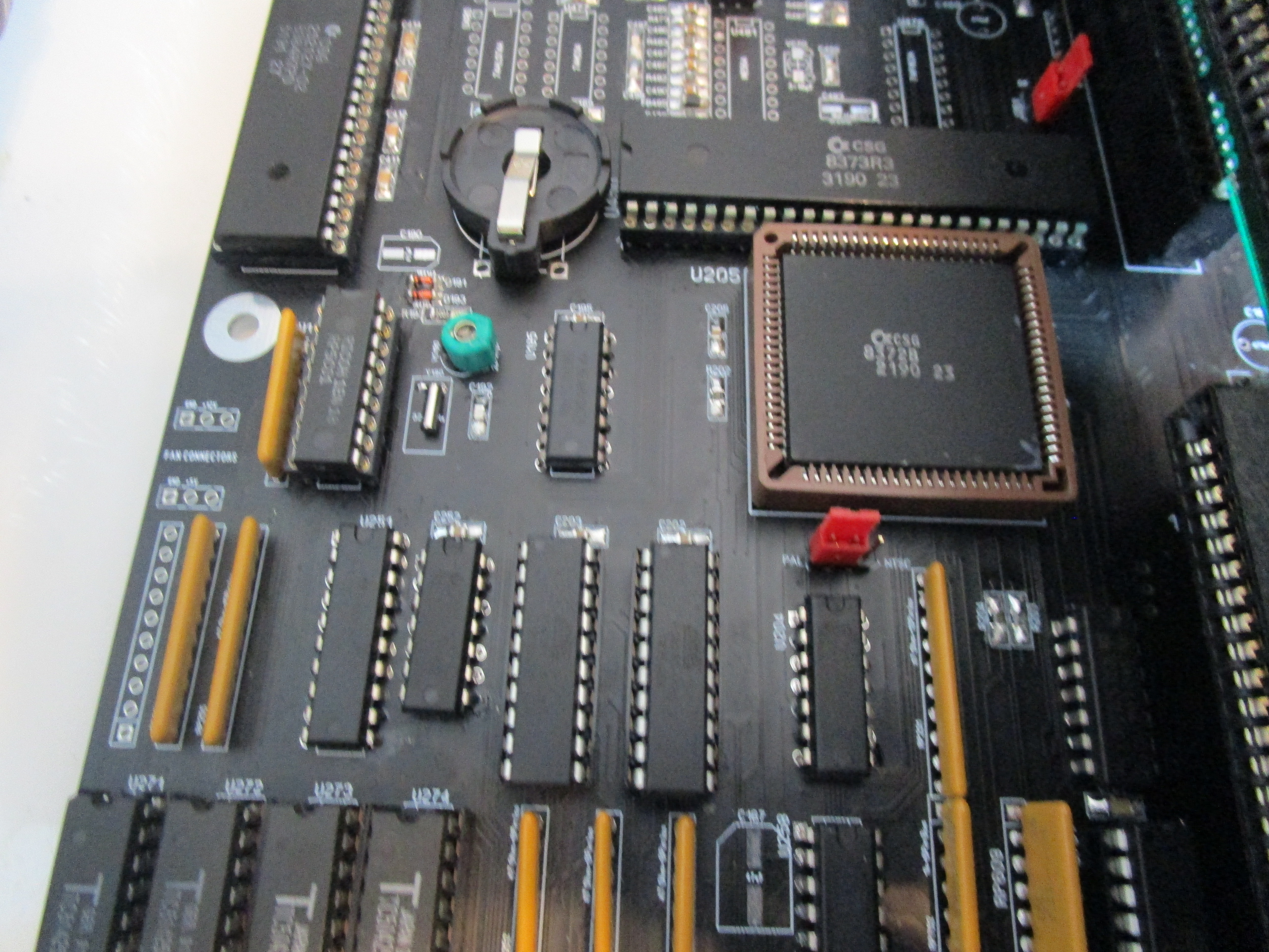
Time for the RTC:
Populate U195 (74LS174), U190 (RP5C01) (I would recomend a socket for it), VC190 this is a trimmable capacitor will make another separate post about that. but generally 22pF is ok, wrong speed and clock drifts some), and also Y190 with a 32768Hz oscillator and the batterysocket. Remember that the ReAmiga does NOT support chargable batteries anymore:
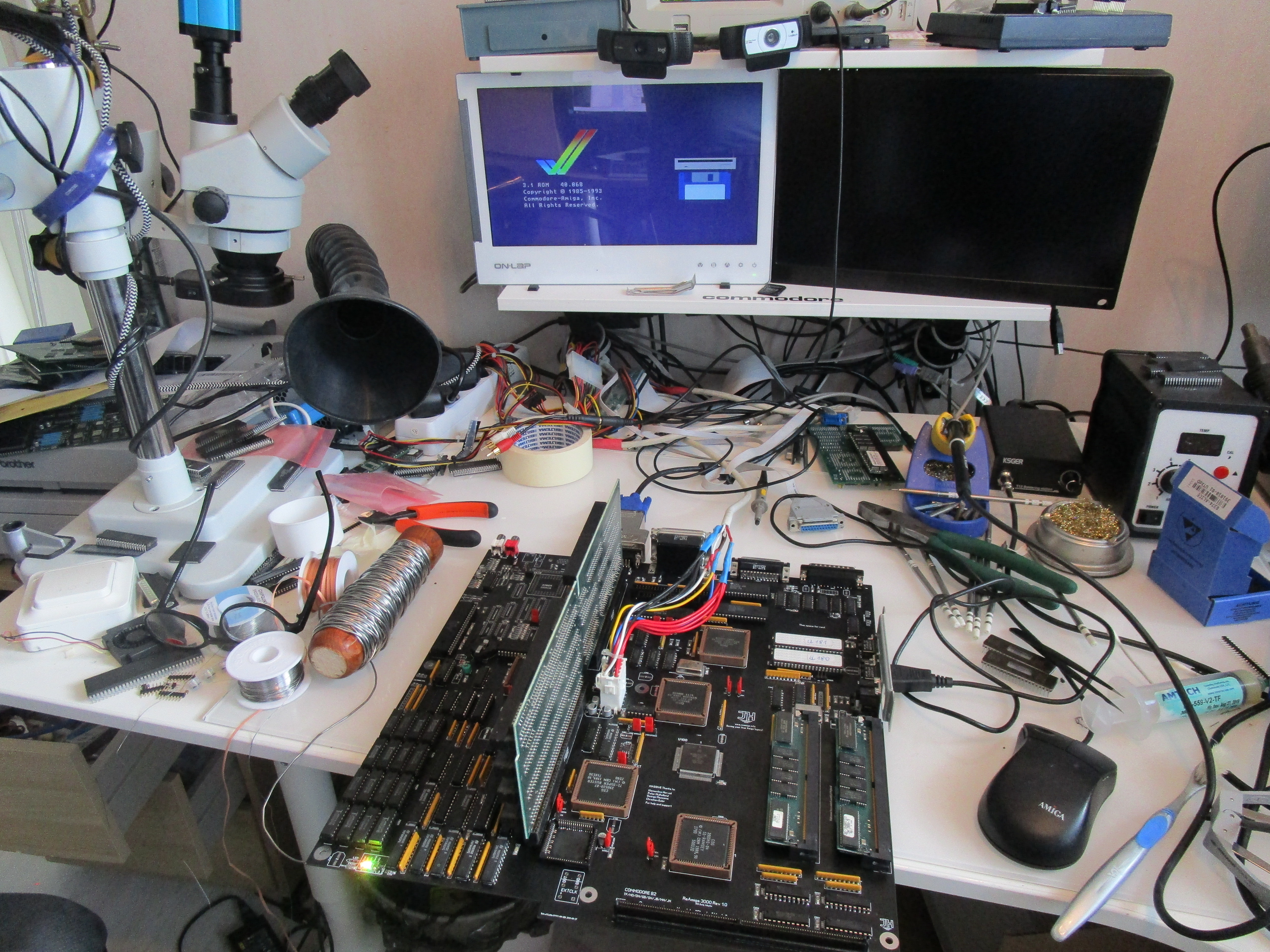
And actually! now you can put in Kickstart roms, add your Daughterboard (DiagROM works without it, Kickstart however will give you a yellow screen with it not present). and VOILA:
Next time is the last step: the Scandoubler/Flickerfixer
Hello , what a fantastic job, you have done but i have a few questions
I made de replica but i have had some problems to find Agnus, dmac and daughter board.
For agnus, i solved the problem with an adaptater that allow the use of 390544-01 instead of 8372AB
For the daughter board , i have read that a pull up resistor 220 ohm between dtack signal and +5v solve the problem
But no solution to find a dmac rev 4 with ramsey 07 and no solution to find a ramsey 04 with the dmac 02
the diag rom works fine, and all is ok but when i put kickstart with only ramsey 07 without dmac i have a black screen
Is this kickstart 3.1 behaviour normal ?
Can You help me ?
Without DMAC you will end up with a black screen.. I do not know if you can bypass this sadly.
thank you for your reply
There may be a solution and I would like to know your opinion.
You have written the Diag rom program which starts without problem without the SDMAC
This means that the SDmac is not essential to start the amiga (unlike the CPU). It also means that the black screen with the 3.1 roms when there is no Sdmac, is a software problem and not a hardware one.
Do you think it is possible to code Kickstart software equivalent to 3.1 but able to start without the presence of Sdmac
What language is used to code the kickstart ?
Is it possible to find the source file of Kickstart 3.1, in order to modify it later ?
I believe Kickstart 1.3 does not support Scsi. Could we have a machine that start with this Kickstart and without the SDmac?
Thank you very much
best Regards
well you COULD do a rom that works without the SuperDMAC .. if you have the sources.. 🙂
maybe mixing different modules in kickstart it would start. never checked it
Hello. Just a question
Do you think that the Dmac 390563-02 can be used in the A3000 instead of using the 390537-02 or 390537-04
is there a specific version of the sci Chip WD33C93
Best regards
Do you MUST have SuperDMAC