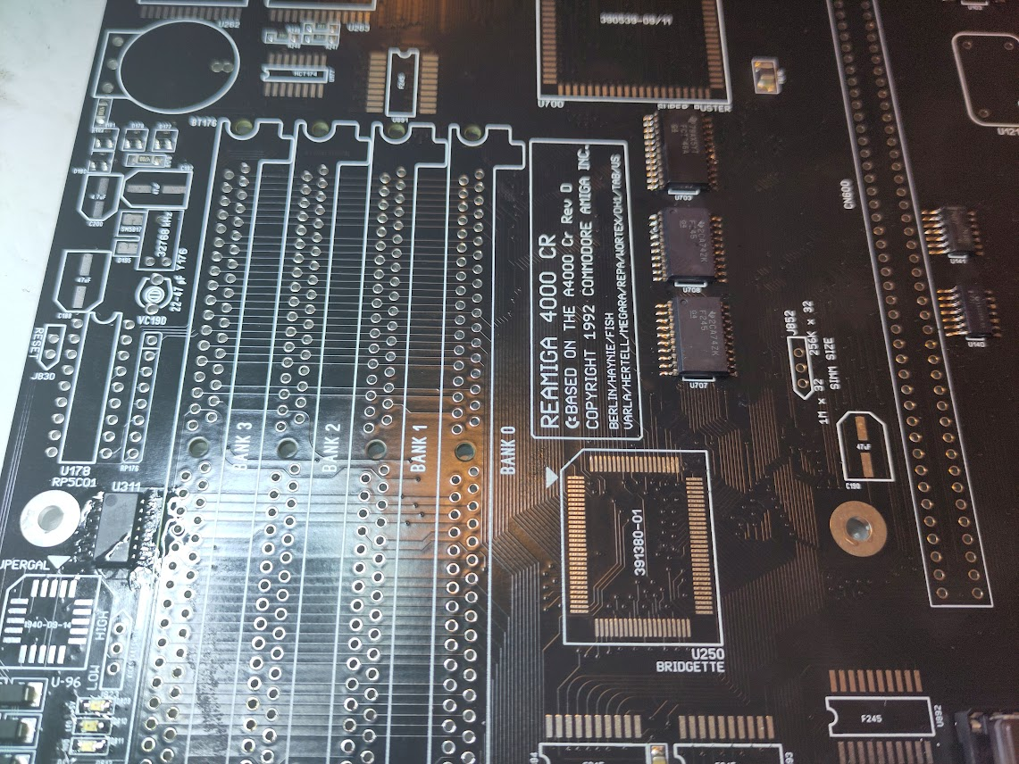
This time it is time to build an ReAmiga 4000CR..
Info and downloadable files at: https://www.reamiga.info/?page_id=165
Locator available at: https://locator.reamiga.info/locator.php?project=ReAmiga4000CR
As usual with my guides. read them through. and when building STOP if you find that my guide does not match with your reality. do not skip things or so. if my guide says one thing should happen and it doesn’t for you. STOP and look if you missed something or made a misstake. do NOT just randomly build things.. I provide photos of states of machine so you can compare etc.
Also this guide like all others CAN contain corrections etc. this is why you should read ALL before building also when visiting back if you had an issue as there might be an addenum to the guide.
As usual we begin with a board with all the passives on. (resistors, ceramic capacitors, diodes, transistors etc) I do NOT put electrolytics at this time as it is not recomended to have them on when doing a ultrasonic clean. add them later.
This guide is KINDA similiar to the 4000 built, just some small changes. but I also changed some order of stuff as I found it more easy build this way)
This guide also works for Heses ALICE board.
I default to you understand that GAL chips (16V8) needs to be programmed and have a proper good programmer that actually handles GALs..
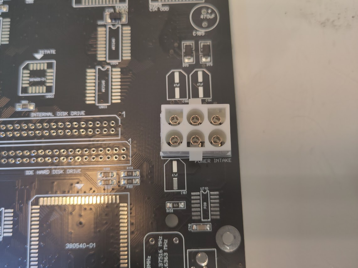
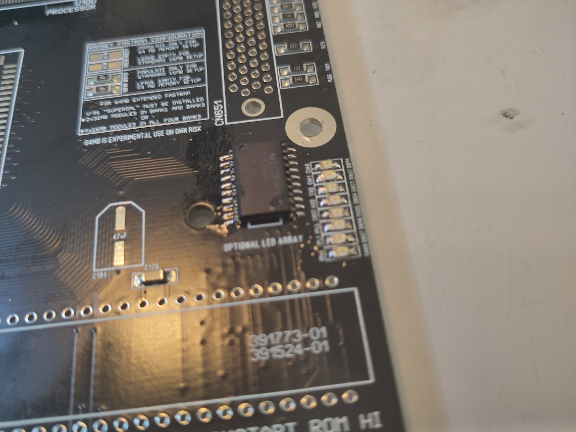
So a plain board. So lets start with Adding the Powerconnector and I add the optional leds. if you do not want leds on the board this can be skipped.
So . Powerconnector, Headers for front leds (do not skip this) and then optional: U801 (74LS240) and the leds. What color is totally up to you! I use green for +5V, red for _LED and blue for IDE (that you will notice will be lightly lit all times) and the rest. well all up to you.
So when you power up your machine you shold see the green +5V led:
(And as usual this is the same as you see the powerled on the original A4000 bo on. so a led is not a sign of working machine. Changing brightness is (this green will however not change brightness, instead the _LED will be light when brightness is changed)
Now it is time to do the Reset as this is important to work for anything.
Add: U140 (74F32), U141 (7407), U710 (74F08) and U160 (74LS38):
Now it is time to get a sync from the RGB.
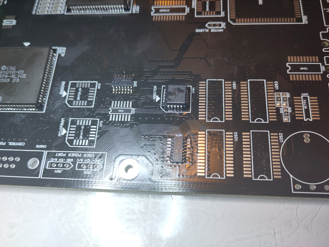
Add U861 (74LS08) This is the new H and V Sync buffer (NOT Available on Hese ALICE board if you are building one)
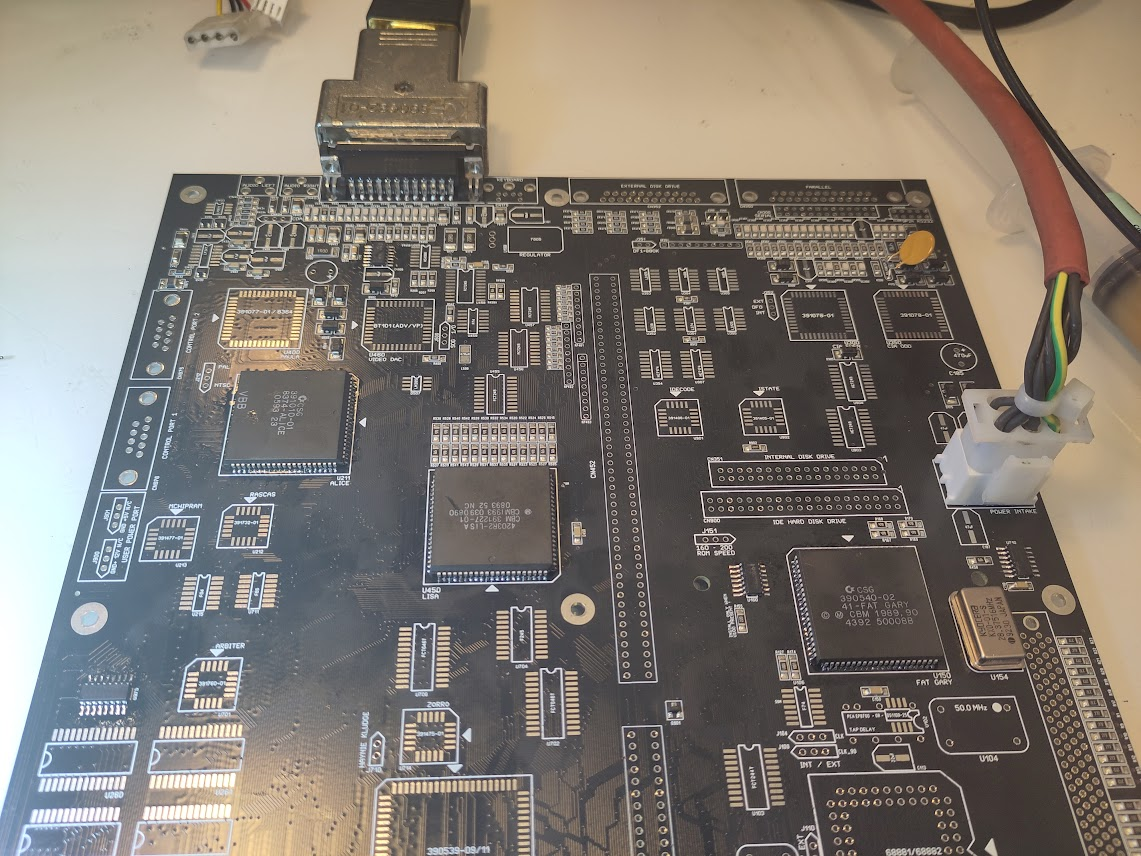
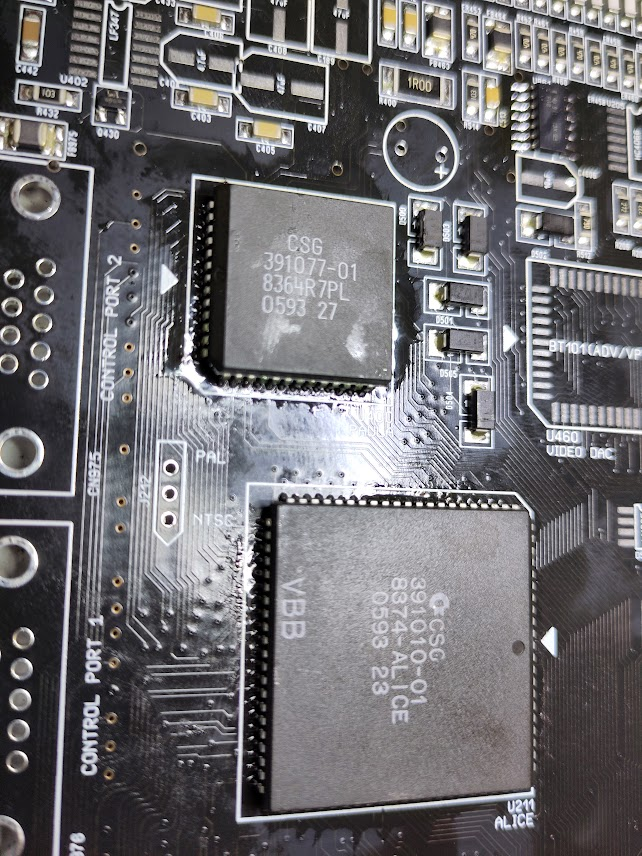
Also add U975 (74HCT166), 28MHz oscillator, Fuse F175, Gary, Alice and Lisa.
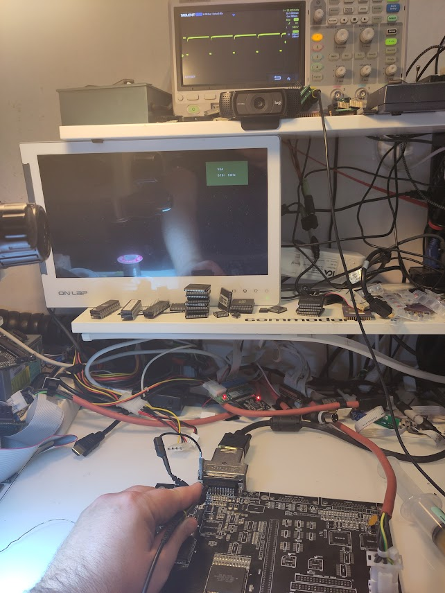
When powering on you should get a V and H sync and some monitors will wake up. but not all monitors give a splash-screen like mine does:
So lets add what is needed for a CPU Clock:
Add U106 (74F74), U103 (74FCT244), U102 (DS1100-25 either SMD or TH version)
Add 50MHz oscillator, Solder in CPU Jumpers and set to correct for your cpu solution 030 is INT!)
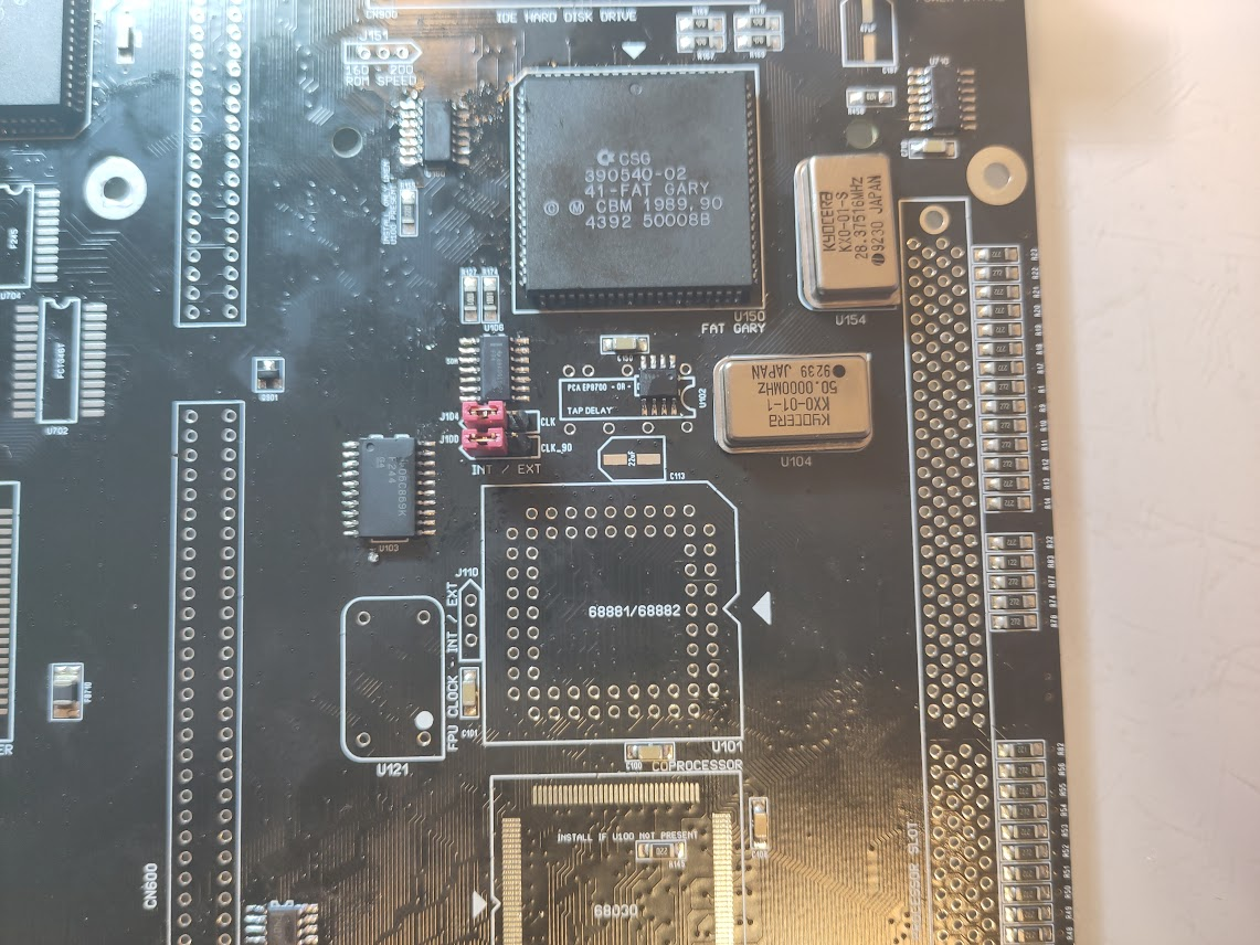
Now we want to make it run code. but FIRST make sure IRQs is handled:
Add U701 (16V8), U711 (74F86):
Now lets add so we can run code:
U354 (74HCT174), U350 (CIA 8520), U901 (16V8), U311 (7407), U703 (74FCT646), U708 & U707 (74F245)
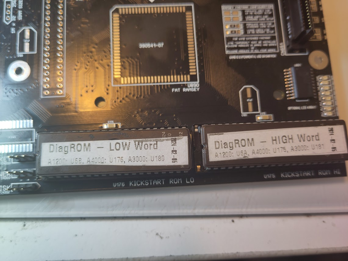
CPU Socket, ROM. (populate ROMs with DiagROM) https://www.diagrom.com/
You might notice that the rom sockets contains one extra pin this is for the “kickstartswitch” option, let pin 1 be empty using normal ROMs. (like on A1200 etc)
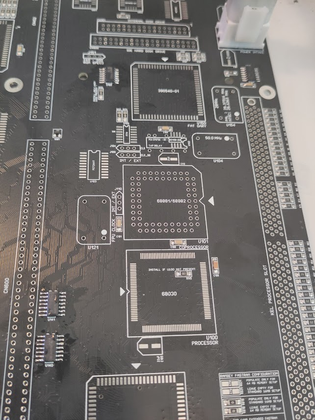
Now the CR can have a onboard CPU. add this now. IF so. there is a resistor R145 there. REMOVE if.
if you do NOT want to use a onboard CPU, there is another resistor close to Gary R155, REMOVE THAT!.
so Internal cpu: NO R145 but R155 populated.
no internal CPU: R145 populated,, R155 NOT populated!
do NOT add FPU etc at this moment. just cpu if so. this build I do will use a external CPU card so I will not populate the CPU.
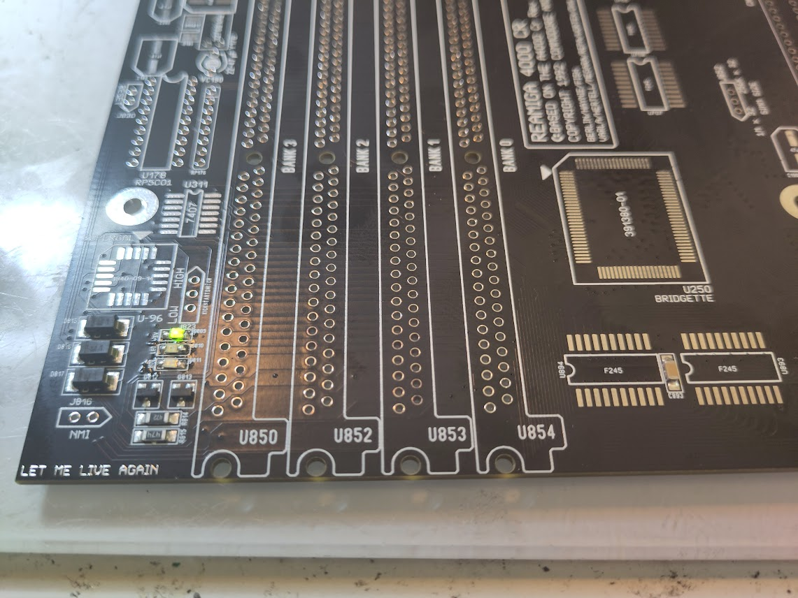
Also I will put in sockets for U901 and U902 for future PIO upgrades. ONLY use sockets if you know how to solder them, most issues people have with their build IS due to sockets,. (U902 will be onpopulated at this moment):
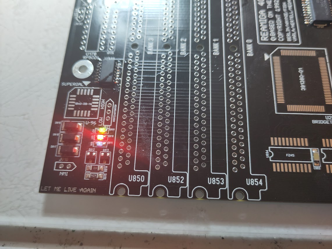
Now when you poweron you should get _LED flashes. or atleast it will be lit.
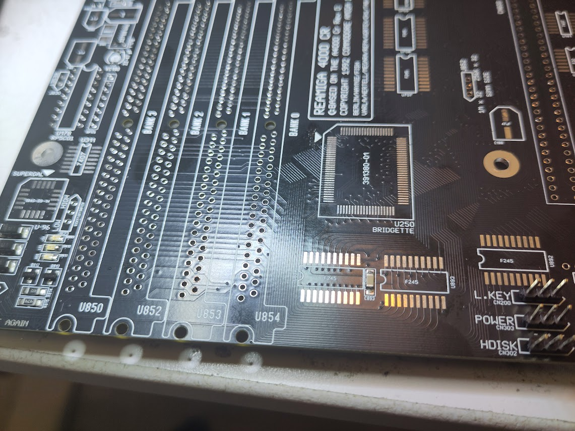
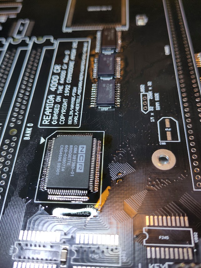
Now you can add Bridgette. after this led flashing might change how it behaves. usually it stays lit only. fully normal!
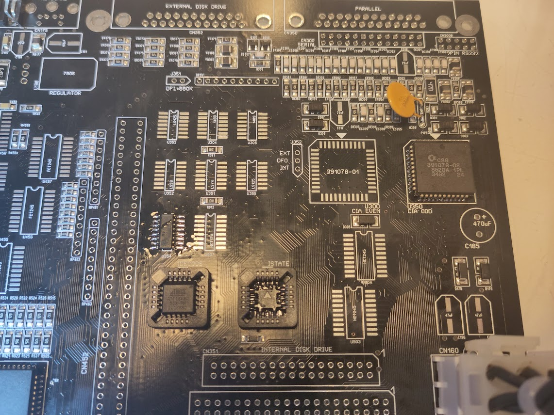
now lets make the serialport work.
Add Paula, U304 (1488 for Recieving data), U305 (1489 for Sending data)
Serialport (26 pin header) OR PC Compatible 10 pin header. (both are same serialport)
and NO, this is not a mod by me. Commodore chosed to use a IDC Serialport on the CR (Cost reduced) version. this is why I added the PC Compatible port as those cables you can get thrown at you from a PC company) or you have to fix a IDC cable and build your cable for your serialport.
NOTE: Amiga have 26 pins and Dsub have 25.. on serialport skip pin 26..
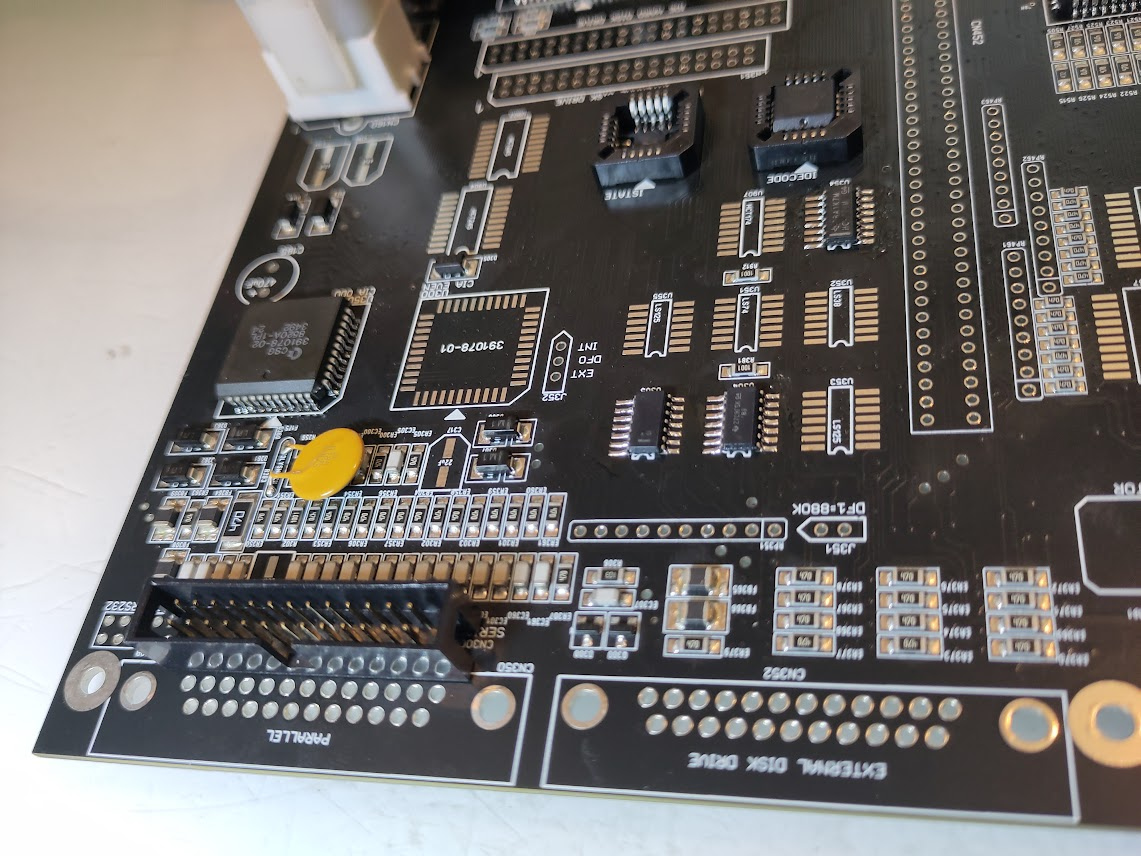
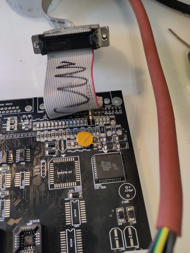
Now Diagrom will putput data on seriaport. and you will notice that the LED led flashes slower. also you can see on the optional led output close to the cpu slot the serial out is making that led flashing.
I think this is a good place to stop Part1, next part does the “fun” stuff
Hi John, I`ve reached the end of part 1 of my build and I`m not getting any serial output. All Amiga chips are NOS and I`ve used a Zeltek Superpro 610P to program the GALs. I`ve checked all solder joints and there`s no bridges. Any help would be very much appreciated. Thanks.
are PWR LED flashing anything?
can you see any flashing of the LED marked TxD?
it is sadly also VERY common with fake qfp 030s. usually you notice that that ALL (!) pins are shorted
Nearly forgot to say with the onboard cpu the led flashes quickly for a few seconds then goes out. With a cpu card the led flashes quickly then stays lit.
TXD and CIA0 stay lit also.