This is the story how to reverseengineer a 040 board, and take it to the next step.
This board is shown for the first time at Amiga32 in Neuss/Germany
TL;DR: files at bottom of this post!
The Commodore A3640 is a well known CPU board for the Commodore Amiga.
It is also know as the 040 board that is ordered as the WORST CPU board ever…
AND it is true..
BUT! this board is the only we have with all data on all chips.. all GAL data is released by Dave Haynie some time ago.
Anyway. the story is as those boards suffer of leakage of the capacitors,, especially as THREE of them are from factory mounted the wrong way.. they LEAK and destroy the PCBs. they simply die.
aprox 2 years ago.. I was thinking of a good way of reparing those boards. and apprentlty one of the biggest issues is the leakage killing the PCBs. I was thinking of a way to check this.
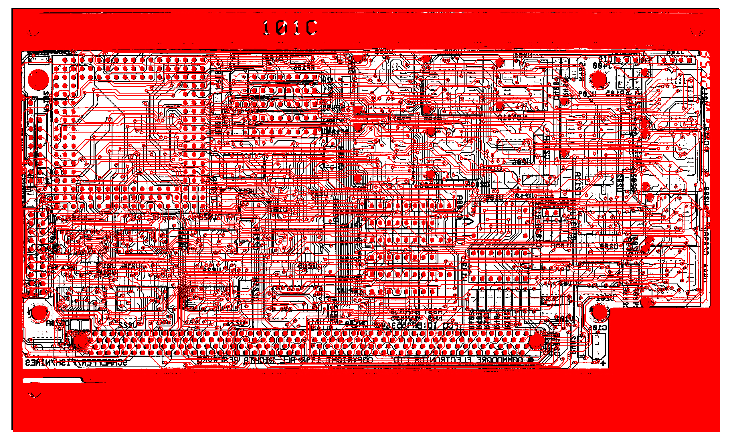
I found the photos of bare PCBs on the internet. I asked people of making a black/white version of this so I could mix the traces so you simply could follow the traces..
And a firend of mine (Klementino Horvat in Croatia) told me he could try to make them b/w.. and well he did:
Mixed together it looked like:
this was the first embryo for my next project:
To simply make a rerace of the A3640 board.
so I did
Render looked like:
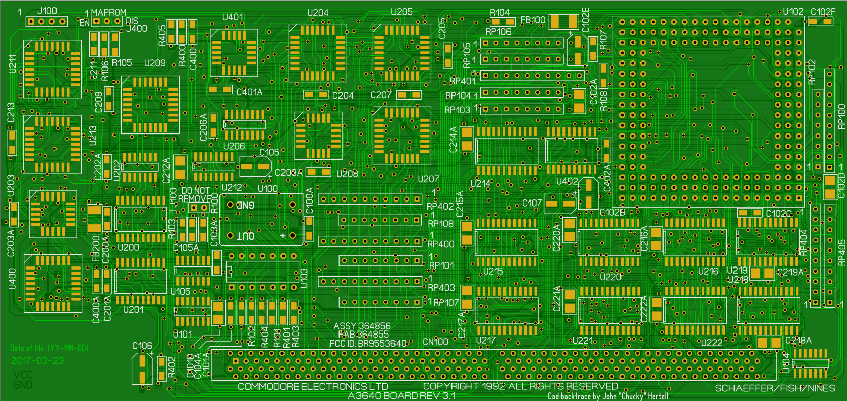
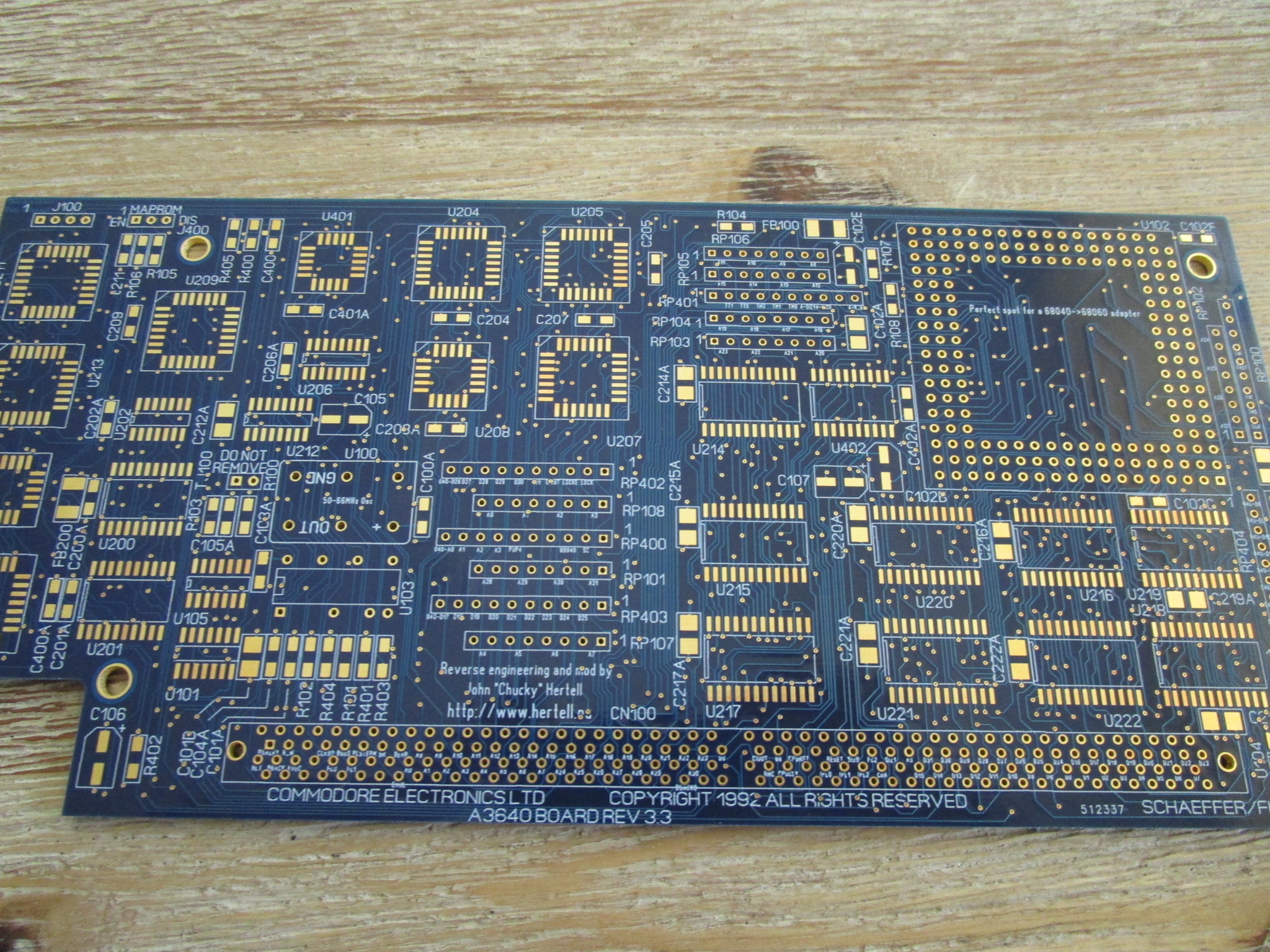
and real board:
This was my first step in producing new boards. First the 3.3 show rendered here. and then the 3.3.2 where I removed the unnecessary jumpers (J100 and the Do Not Remove jumper) also made some changes in GND and VCC planes.
and this is where I planned to stop. People asked me about implementing the 040->060 adapter but the software I am using is a pain to do changes in the PCB so.. nah..
Until I was thinking. well. hey. why not, it would be neat that I do not have to solder those damn adapters as I think they are a pain to solder. (with risking doing it wrong sending 5V to the 060 cpu etc etc)
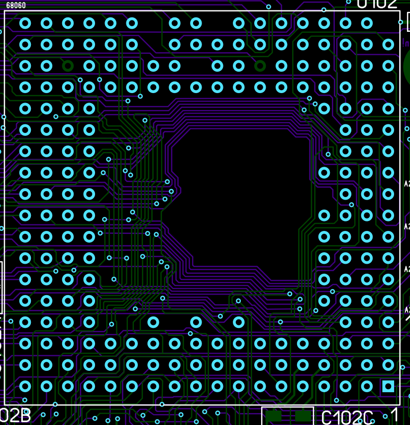
So, I started to think.. where to put the extra 74F257 and resistors and caps? well.. first clean up traces inside the 040, making room there. putting the pullup resistors on the topside under the cpu, and putting the 74F257 on the bottomside.. took some painful hours (days) of rerouting traces:
and indeed, I managed to clean up the area enough to fit the 74f257 needed for the adapter. and as I would need some resistors there, the 1206 size would not fit, so I simply changed ALL SMD components from 1206 to 0805. and as 0805 is cheaper anyway. winwin.
So now I just needed a place to put the voltregulator. and this was an issue. as I want to as close to the 060 as possible.
So.. I figured out, IF I remove the resistorpacks close to the cpu and put them on the backside, I would get space for a voltregulator.. so I did.
But after doing those. I just could not the rest of the resistorpacks be there as it looks odd with resistors on some locations and resistorpacks on some. so. I changed them all. Why did I not use SMD resistorpacks? well this is just lazyness as a reason as that would mean even MORE re-routing. so I skipped that.
So now, I had space for voltregulator and removed all holethrough resistorpacks.. time to do the 3.3V voltageplane.
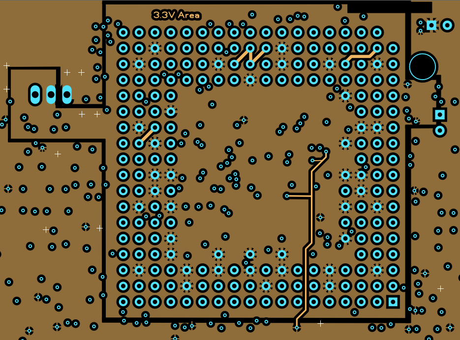
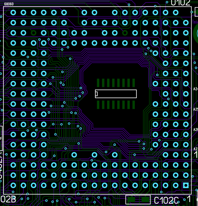
And this is how it looks like. if you wonder why there is some traces between some pins on the CPU. the explanation is in the GND plane:
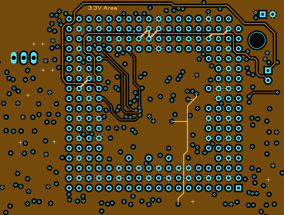
The reason is, I ran out of possabilities to do traces on upper and lower layers so I had to do some internal ones. especially to introduce the THERM0 and THERM1 pins (more about those later)
this made the GND plane there somewhat tight. that is why I added extra GND connections in the 3.3V side.
you can also see that I draw a small tiny trace from the 5V area to the 74F257 chip inside the 3.3V area, as it needs 5V to operate.
if you look at the first pictures of my retrace of the cpu socket, you can see that I originally planned to have 68060 ONLY. after talking to marmes and he gave me a simple hint of how to disable the 040-060 socket, I put back holes so you can have a 040 ASWELL. (as my original plan was.. A3660 will be 060 only)
Anyway. after a while. I got it all in there. and as there was some free space on the side of the board I added the pins THERM0 and THERM1 frm the cpu, it is internal pins from the 060 cpu that you can use to check die-temperature. there is no more connection or so except to those jumperpins. But it is now easly reachable for you to do some magic with an arduino or so to do temp-regulating or anything.
I also added a +5V powerconnector for fans. Strangly enough the CPU slot does not contain any 12V pin so no “normal” 12V fan can be used.
And there is a 040/060 “jumper” (via a 1Ohm resistor) that disables the 040-060 adapter. so if you will use a 040 on this board set that jumper to 040 mode. AND skip the voltregulator, and put a jumperwire between the IN and OUT pins of the regulator. this will make the 3.3V area having 5V instead. (do NOT connect a 060 cpu in this case or you WILL fry it)
but except this, this board is technically just a 3640 board with internal 040-060 adapter. So this have a drawback. IF you have a full 060 cpu (with FPU) your machine WILL end at a endless guru. So you still will need a custom kickstart that disables the FPU at poweron. (that setpatch later enables.) and this is the reason I call this a “Seminative” 060 card. YES you can have the 060 CPU with no adapter. BUT as this still lack a ROM that disables the FPU at poweron as ordinary native 060 cards does and is dependent of a custom rom. this will so far only SEMInative 060.
BUT as adapter is not required, this WILL also fit in an A3000.
ANYWAY!? the result you may ask?
Well I did a first run of 20 board (I got 24) and I made them BLACK. My plan was to give those boards to people that have done good in the community. (AND I sold 2 in total)
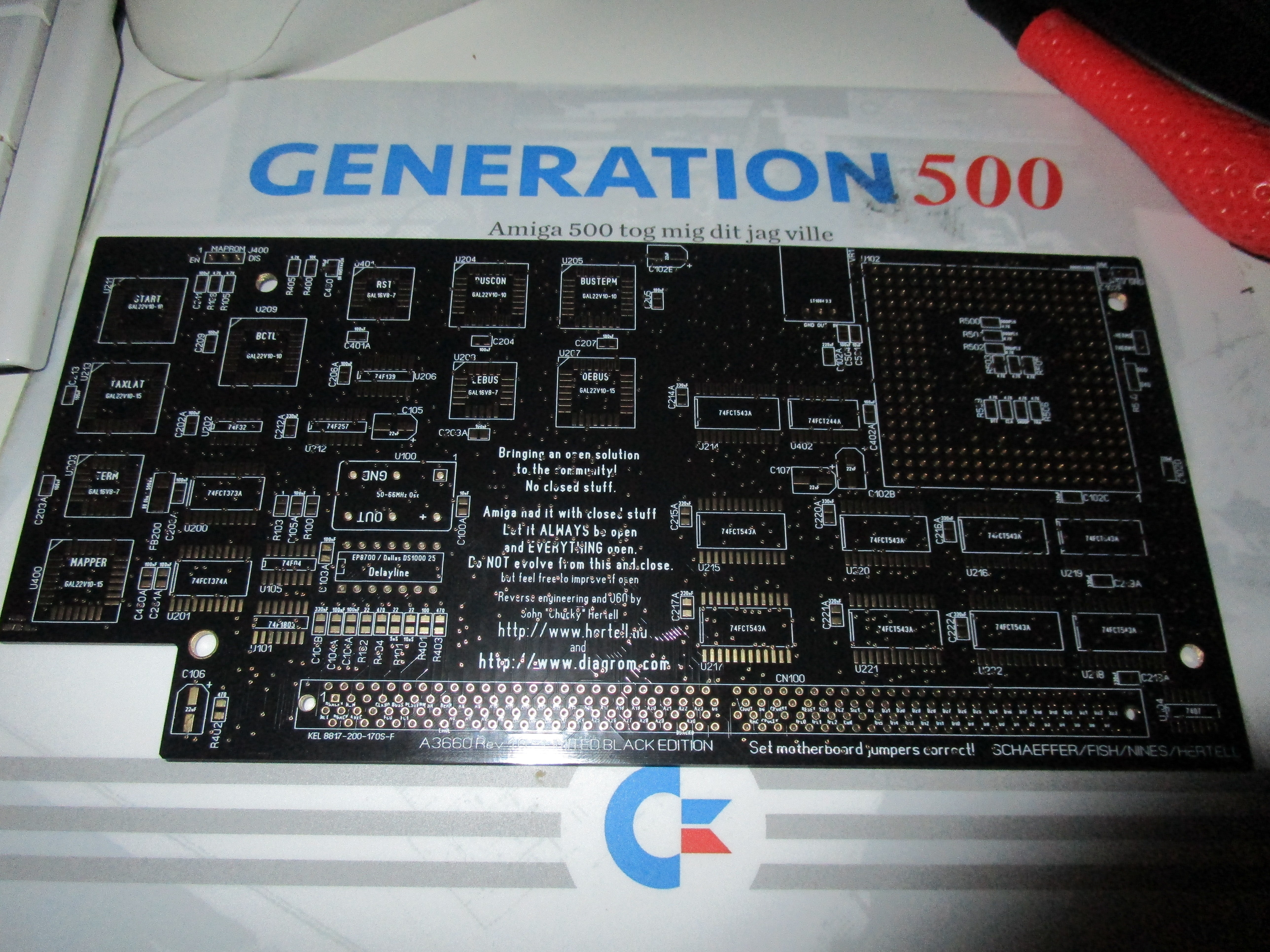
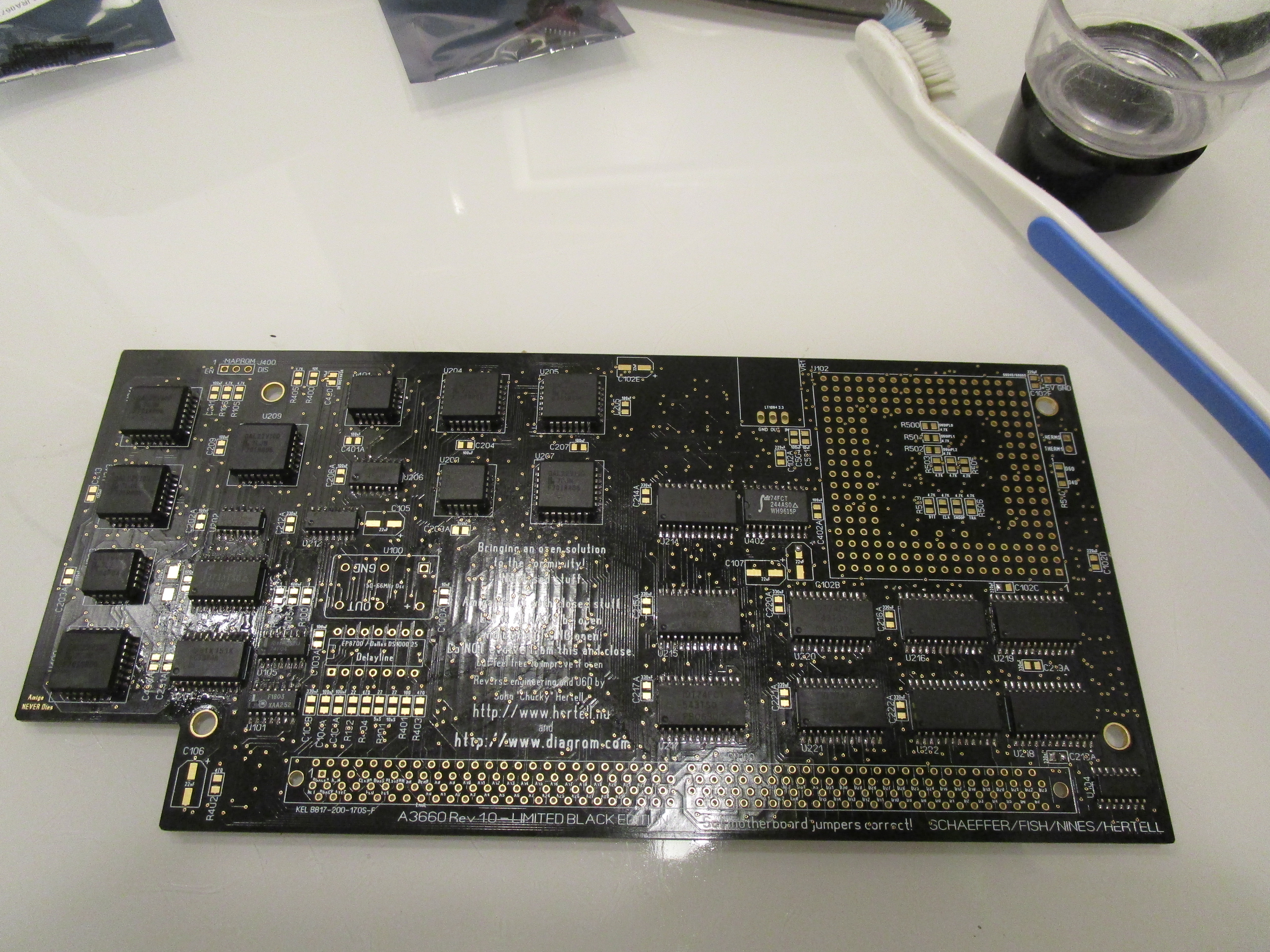
And this is the “final” build:
And if you look closly, there is a 72MHz osciallator installed. and IT SURE DID BOOT with it. but I would NEVER recomend you going higher than 66 as overclocking (over 50MHz) will overclock parts of the motherboard and might create issues.
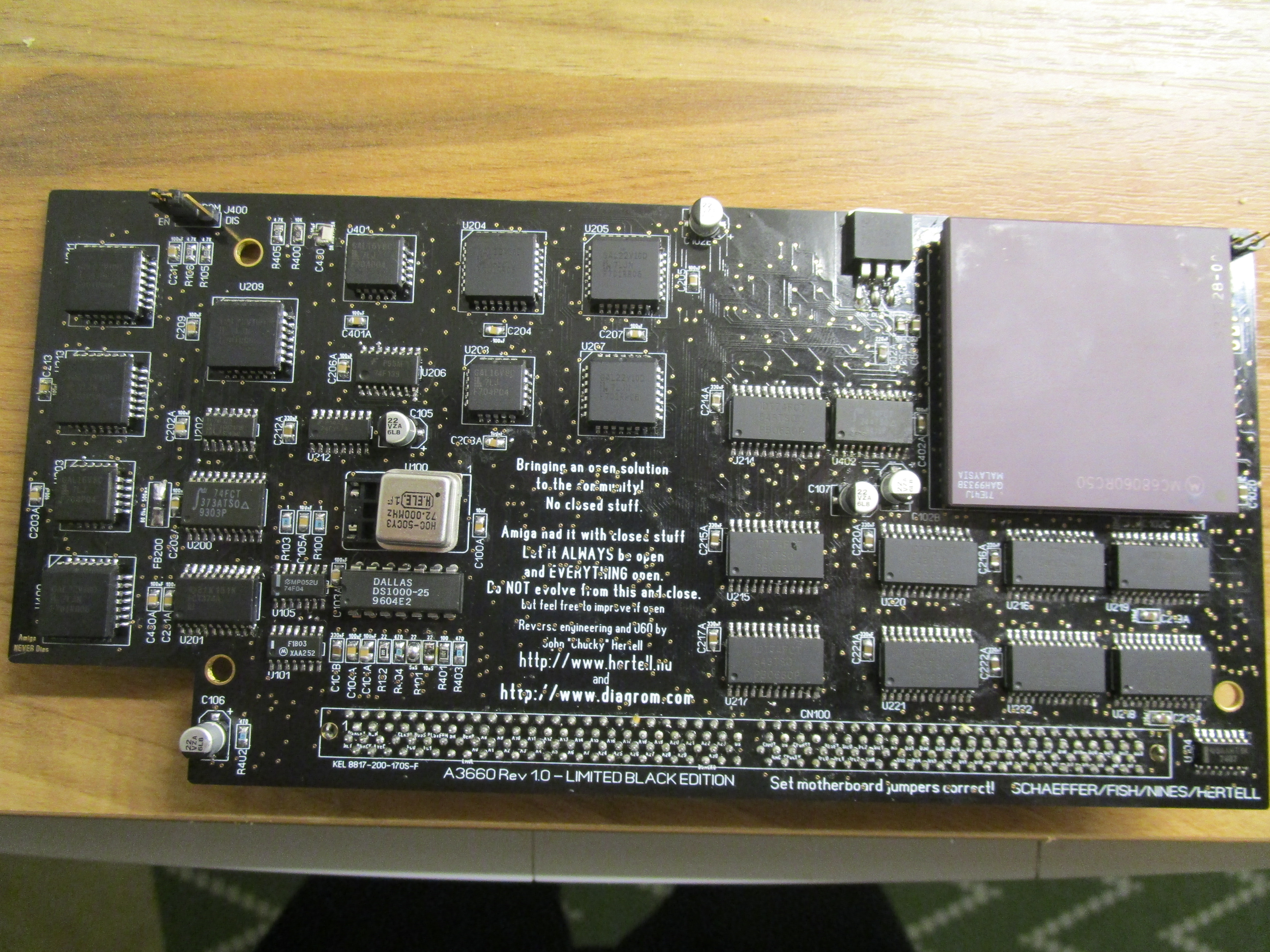
but at aprox 21:00 the 9:th of september this year, the A3660 booted for the first time. after some minor solderissues. (the resistors that replaces the resistorpacks are a TIGHT solder.. it is easy to short a via. I have actually changed that area in the files I will release here to make that more easy, but the boards I made after this have the same layout as the black board (but being blue).
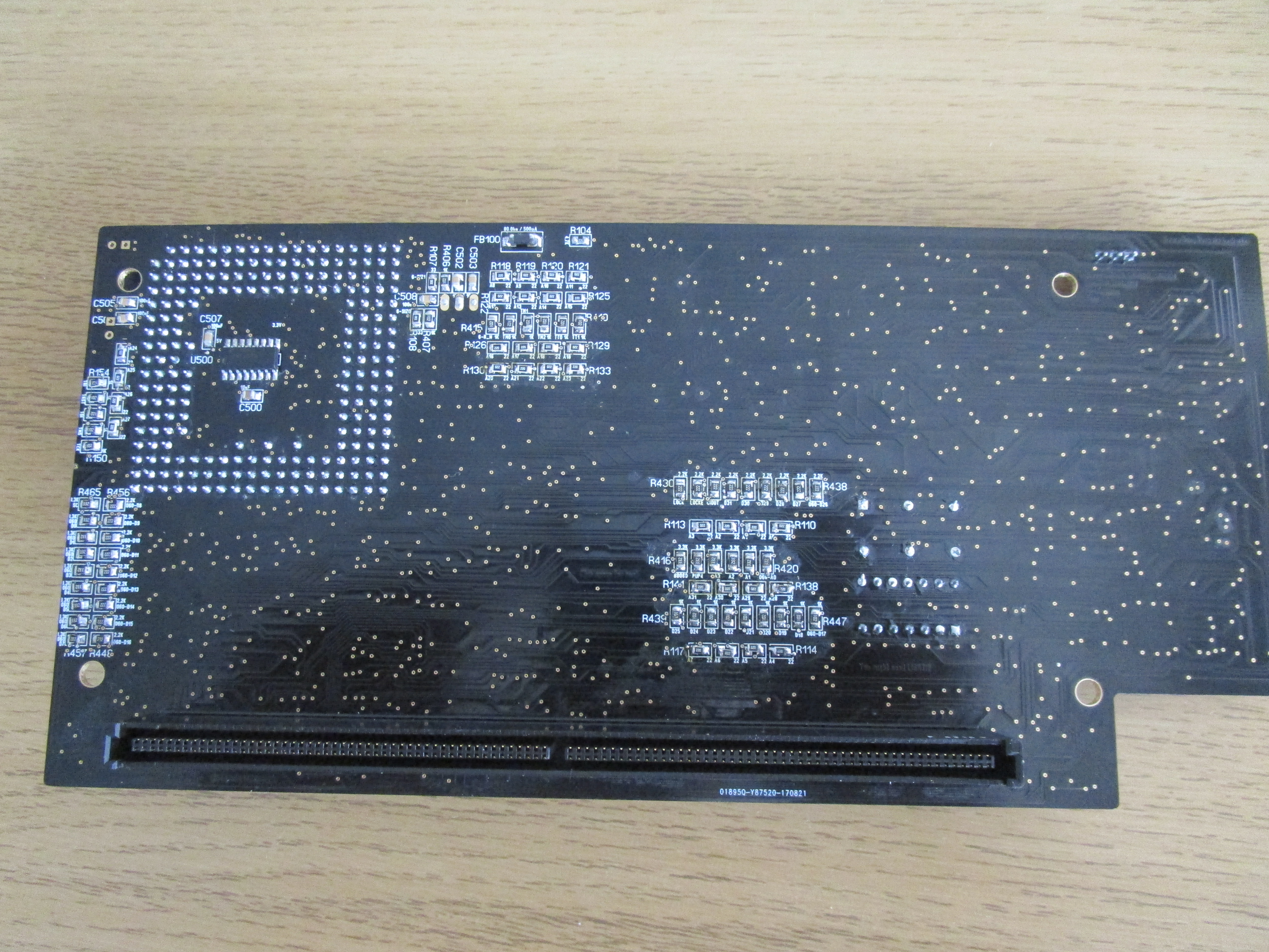
After doing that 3660 board I removed all gals, put in sockets and also inserted a 68060 compatible ZIF socket.. this is for me to use when I test GALs or CPUs. and this nice baby looks like this:
Front:

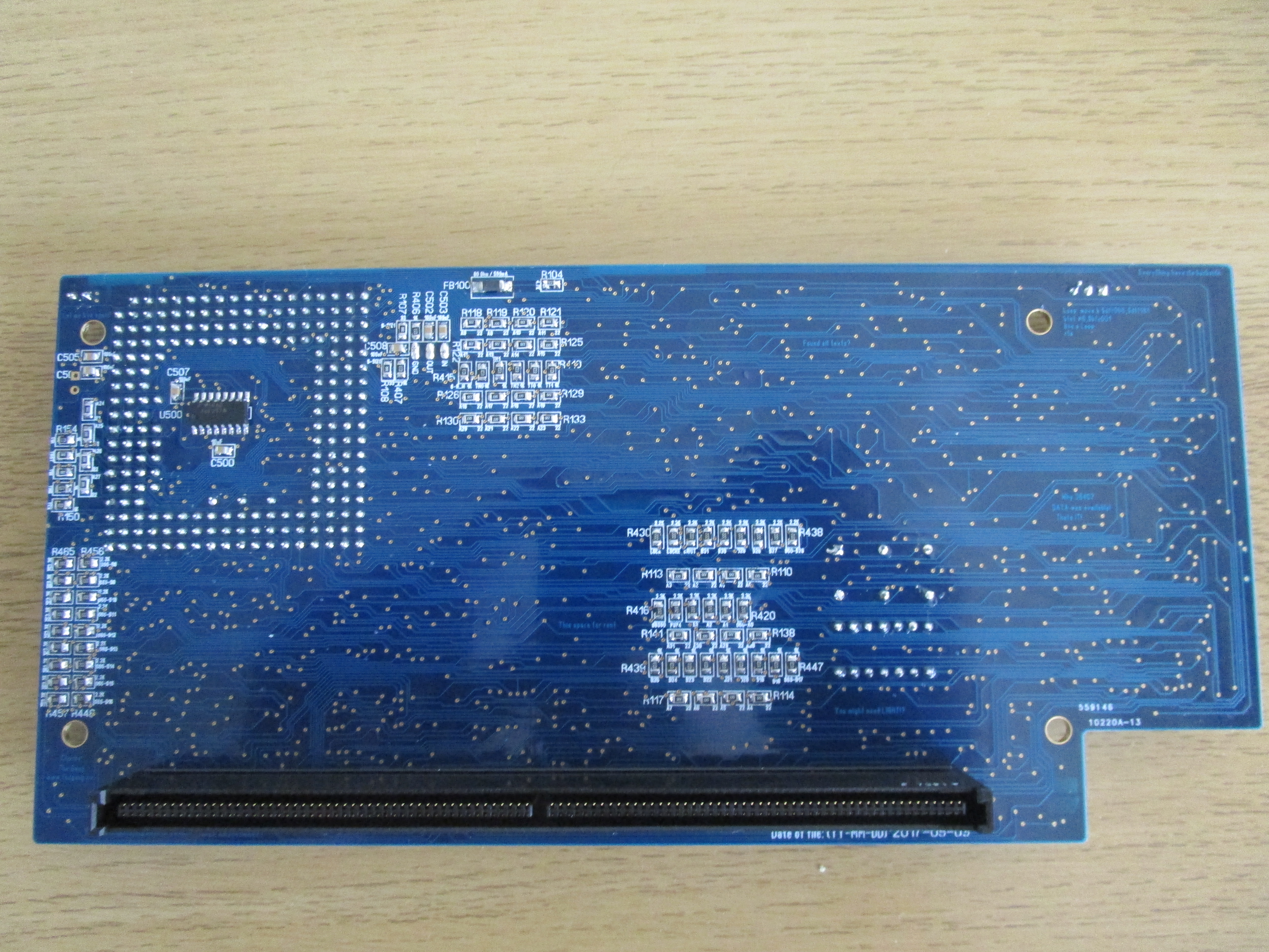
Back:
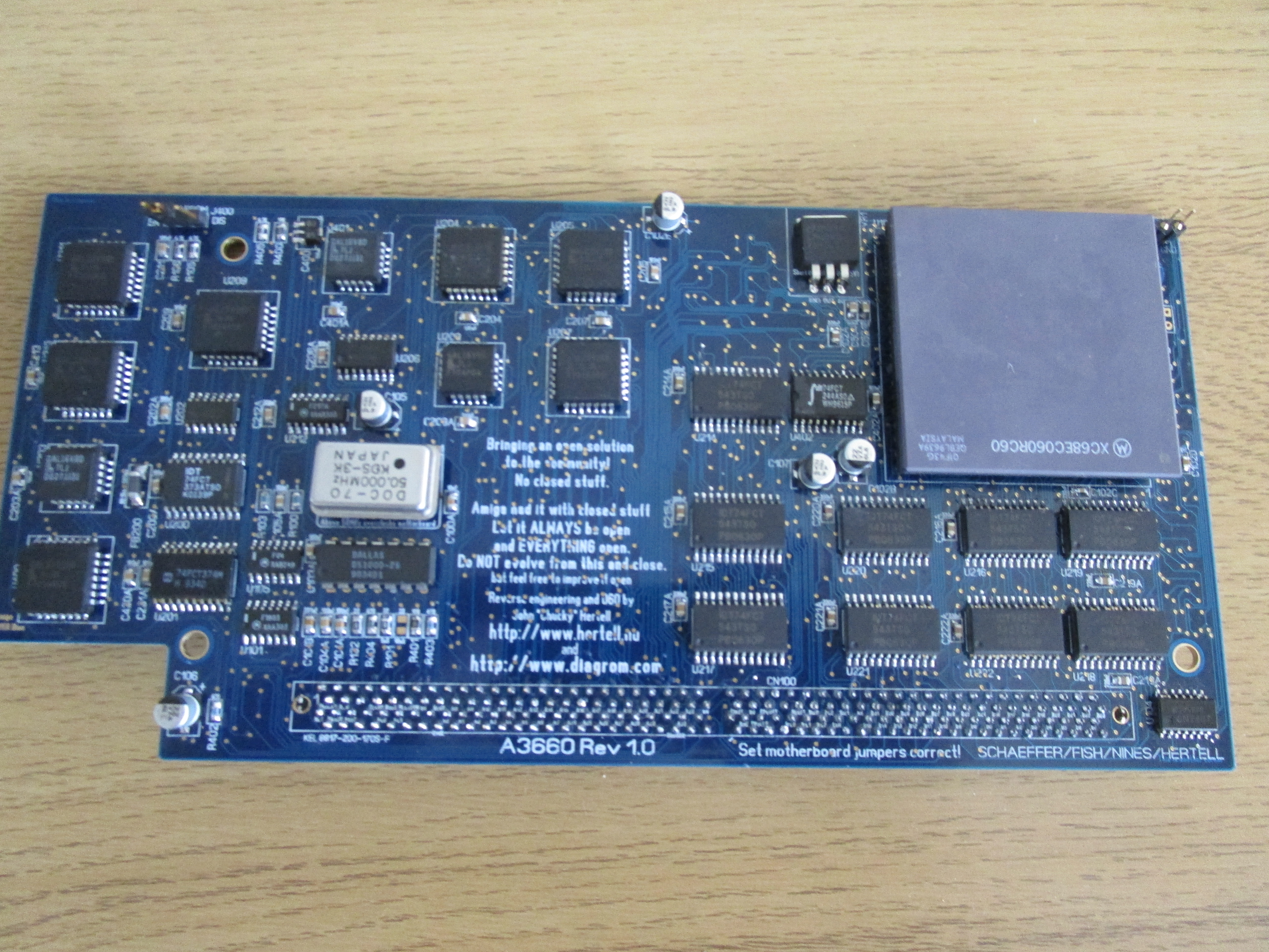
And a fully assembled BLUE board with no sockets etc: (This board you can have a look at on Amiga32 as I will bring it)
However.. lets talk about OPEN!.
YES! you will be able to download ALL my files. you are free to do own pcbs. you can sell them,. you can offer repairservices, I do not care what you charge, if you do it as a private person or company.. the important thing is that you offer the possability of getting people to use 040/060.
BUT! please, PLEASE , PLEASE to not use this data and do something own and close it.. THEN I will be pissed. and only then.
This solution is released (and shown) first at Amiga32 in Neuss. sure there is people knowing about this (especially those who already had got their black boards) but I have not spoken anything about this in forums.. actually just for the fun to show it as a surprise at Amiga32.
There is technically NO difference between the black or the blue boards. it is just that the black boards are for me to show some people that I like what they are doing for the community.
Also I will sell PCBs for 35Eur, this will contain some SMALL changes (like small eastereggs) compared to the boardfiles shown here. and the only reason for that is that you will get some support/help with solderissues if you bought those cards. I will try to help but cannot physically help you if you done the PCBs on your own. But there is NO technical differences between them.
WHAT is the next step? Well I will move this data to eagle so you can develope this. I am NO hardwaredesigner atall. but PLEASE talk with me if you have ideas. let us make this great. and lets not make double-jobs.
BUT THE FILES!?? I NEED THEM NOW!!!
Yup.. I bet.. 🙂
Here you can have all files to make PCBs for the A3640 Rev 3.3.2:
http://www.hertell.nu/webfiles/A3640Rev33.zip
And here all files for the A3660 Rev 1:
http://www.hertell.nu/webfiles/A3660Rev1.zip
I have made an addition to the Rev 1. the 1.1 it have the alternative to use a 74F175 instead of the 74F803 clockdriver.
and a SMD delayline.. I also moved some traces to make a better clearance between pins of ICs etc. so some fabhouses that supply a not that good soldermask can be used.
available at:
http://www.hertell.nu/webfiles/A3660Rev11.zip
I used seeedstudio to produce the boards using this:
PCB Dimension – 97.5mm*206.2mm
Surface Finish – ENIG
Min Solder Mask Dam – 0.4mm↑
Copper Weight – 1oz.
Half-cut / Castellated Holes – no
Min Hole Size – 0.3mm
PCB Color – Blue
Material – FR-4 TG130
Layer – 4 layers
Blind Vias – no
PCB Thickness – 1.6
Min Tracking / Spacing – 5/5 mil
GALs is still the A3640 ones:
So the original GAL files can be downloaded from: www.hertell.nu/webfiles/A3640.zip
There is also a hack to remove 2 waitstates improving memoryspeed. This CAN be instable if you use a quaddoubler.
But works fine with the 68060: Hack is made by speedgeek and can be downloade from:
www.hertell.nu/webfiles/A3640_ST_MOD.zip
(just replace the GALs in this archive from the A3640 ones. and you are ready to go)
Good job, John!
Thanx!
Thanks for making this board and for sharing the files Chucky. It was nice to meet you at the Amiga32.
Regards,
Edu.
It was all a pleasure.. even if it is a lot of work.
Hi chucky
Do you have any 3660 or 3640 boards left for sale
I m not a member on amibay and would like to buy one
Thanks
Albert
Currently no.. sorry.
It would be great if someone develop a RAM board for this cards 🙂
Ram will happen.. 🙂
How do you program these gal chips? Can you do a guide for that?
Or at least can you recommend a good programmer?
I used to have my TL866 programmer, but it was extremly picky what chips it could program
so now I have a Xeltec SuperPro 610P Programmer. it is expensive but it programs every GAL I have thrown at it.
On man. I can’t see forking out the $$ for that. I want to build an a3660, but I have blank GALs.
I used the Wellon VP-290 to upgrade/replace GALs on my old A3640 (with ATFs). It’s about double the price of the TL866CS.
I now use a Xeltec Superpro 610S works perfect
Another question on the GALs.
Would these work for all 10 ? They don’t seem to stock 7ns
https://www.digikey.ca/product-detail/en/microchip-technology/ATF22V10C-10JU/ATF22V10C-10JU-ND/1008554
Sorry… I didn’t realize they were different size chips….
Would these 5ns work:
https://www.digikey.ca/product-detail/en/microchip-technology/ATF16V8C-5JX/ATF16V8C-5JX-ND/1027054
And then these 10ns:
https://www.digikey.ca/product-detail/en/microchip-technology/ATF22V10C-10JU/ATF22V10C-10JU-ND/1008554
never used 5ns ones..
Of course, as soon as someone such as yourself does good and releases the information for free, others take advantage and start ripping people off..
http://www.amibay.com/showthread.php?96514-A3660-CPU-card-newly-built
well.. as I wrote: “YES! you will be able to download ALL my files. you are free to do own pcbs. you can sell them,. you can offer repairservices, I do not care what you charge, if you do it as a private person or company.. the important thing is that you offer the possability of getting people to use 040/060.”
it is OK. and is actually the same price I will charge for the hours it takes for me to solder one board
I just came across this! well done! Id love to see stuff like this for a1200… 🙂
well lets see..:)
Hi John,
Thanks for making this amazing project open. Quick question regarding GALs, can -10 be used instead of -15?
Yes. I am using -10 all over
Wow this is a great project. Thanks for making the design open & your contribution to the scene! Would love to try my hand at assembling one of these, but where to get the chips?
I have got from utsource, ebay etc
Wow really great job you have done!!! Do you have any boards for sale? You did mention a RAM integration. Do you know already when you will announce that new version 🙂 ?
I sell boards at AmiBay sometiems.. now out of stock.
RAM.. well soemday 🙂
Where do you guys source those 74F1803 (F803) chips from?
You can also use 74F803 and I get mine from utsource
Thanks!
What about the Tantalum 22uF capacitor needed for the LT1084? I can’t find it on the PCB design. Moreover, I found to open circuits. I will post you message on amibay.com. You might want to update your files if not done yet.
Was this already solved? I’d like to build one board for me
It i s solved in the Rev 1.1 PCB. haven’t had time to do a testbuild out of it yet.
however the open circuits was to 2 decouplingcaps. so it did not affect the functionality too much and is easily fixed.
Nice work and I suspect it took hundreds of hours of work to do.
Not sure if this interests but I’ve got one of the two (I think there are only two of three according to Mr Haynie) Gemini prototypes – I’ve got the one with very little PAL chips in place if you look at it on the big book of Amiga hardware, its the hardly populated one.
I’ve been wanting to do something with this for a while and if you’re up for it and would like to open the design I would be prepared to lend it to you (I want it back mind). I’ve seen files on the Haynie archives about it but not sure if every PAL is listed there?
Michael
Late answer, this was in spam section. (!)
the Amigas with TH caps does not have the alarming need of being recapped. but they DO dry out so it can be good to do it. but leakage is not common
Hi John,
I just noticed that the …Rev11.zip download link actually gives the …Rev1.zip !
Maybe you like to check….
Best regards,
Ralf
oh. thats bad! will fix
Will there be an A3660 card with fast memory ??
hopefully I will do something. IF I get the time
Hi Chucky,
I’ve built up one of the rev 1.0 boards using components from an old A3640 board, with a MC68040RC40A (and the in/out jumper).
I’ve not been able to get it to boot at all, just black screen. I’ve seen people mention it won’t work with A3640 components, but not sure which specific ones. can I use the old ram-chips etc? .. any idea would be appreciated. I’m pretty sure the soldering is good though.
Thanks for your work on this, it’s awesome to see the community still going
3640 components will work just fine. BUT! you WILL need an extra 74f257 on the bottom side. without it you will not be sucessful.
there are no ramchips on the board?
got it!!
it was an issue with my A4000 motherboard, I bought it as “tested good” ,but found a few dry-joints which I re-soldered, and voila’ [never trust anyone ;)]. Many thanks for this awesome project , I wish i had your skills and knowledge to contribute. Only took m a year to get it running lol.
Any chance of doing a quick Quad-Doubler 🙂 I’m sure it would be a breeze for you and I havent seen one available for a long time.
thanks
Nathan
Have you redesigned the board to use components that were not totally bought up by the Danish jerkoff on Amibay to prevent others from building the cards? He’s got a monopoly on it now.
huh? atleast the reav 1.1 PCB is is quite “easy” to get all components
Probably a future version could be more cost effective using a CPLD e.g. Xilinx 9500xl series (5v tolerant). It could replace all the GALs at least and some of the logic ICs.
Maybe there will be space left in it for a small DRAM controller too.
yes.. maybe for a Rev 2. but first I also want a better cpu solution done..
Hi,
I have one of your cards running in my a3000 and it is working really well. I am getting a few software incompatibilities and random crashes with software which I think is due to the libaries. I am using the MMUlibs with a patched kickstart 3.9 on os 3.9. What have you found to be the best ‘060 libaries?
Thanks
J
I use the phase5 ones
I’ll give them a try.
Many thanks
J
What is going on at C400/R400? Kinda confused as it looks like there are multiple land patterns on C400 and if I can read the text, it says “100nF OR RH5VA43A” and R400 says “100 if C400 is 100nF”.
Checking out the . Is there a pro/con to using just a 100ohm + 100nF on these? I do have a donor A3640 that is dead, but the more I use modern components, the better.
Also, the footprint of C400 looks more like a 1206?
this is typical commodore. in some cases they used the 1k resistor+cap combo in some cases 10k resistor+low voltage detector.
thats why the pad is “weird”
So if I go the resistor/capacitor route, instead of the RH5VA43A, does the 100nF go to the top and bottom pad (and misses the one in between completely)?
pad is for a 1206.. you can use a 0805 and some more solder..
Haha, just found the ground plane easter eggs! Brilliant!
ehhe they are funny 🙂 there is more.. from the boards from me. not the public gerbers 🙂
I must have gotten one of your boards as there were 4-5 messages screened into the ground plane. Very funny.
I’m waiting for a batch of ten PCBs in yellow solder mask from JLCPC, I’ll be keeping two for myself and the rest will be sold to the community at cost…considerably less then the currently overpriced eBay options.
I just noticed in the pic of your blue PCB, you have a 68EC060RC60 mask 01F43G with the LOT/date code QEBK9639A. I have that EXACT same CPU, and hoping since it’s an 01F43G mask that it’s actually a full 060 with MMU/FPU.
Out of curiosity, is yours a full 060?
Cheers!
cant remember if it was detected full. that was one of my test CPUs
Hi, fantastic project, but where to find custom kickstart roms for A4000?
Thanx. I cannot give that due to copyright reasons.
BUT! Kickstart 3.1.4 works aswell. and is available to buy at different amigastores.
So, using standard 3.1.4 Kickstart would make it compatible with 68060 CPU, including MMU/FPU?
yes 3.1.4 works just fine
Why A3660 has various pull-up resistors for the 68040/68060 data (060-Dxx) signals? Some of the signals have pull-up resistors of 3.3k, some 2.2k and the rest 1k? The original A3640 has 1k pull-up resistors for all the 040 data signals.
This is based on the recomendations speedgeek have made of changes of the A3640
Just picked up 2 of these boards at AmiWest 2019. It was mentioned that someone had created a digikey order list to make getting all the parts a bit easer? Has anyone seen that?
(late answer)
no idea. I myself have been too lazy to do one 🙂
I’d like to build a few of those, maybe even try to improve on the original design if time allows. Where do you guys source KEL connectors?
improving is kinda pointless better to do new.
KEL connectors I bought frpm “terriblefire”
Hi Chucky. I am currently trying to use the SpeedGeek GALs on the A3660, but I am only getting a black screen, the A3660 doesn’t boot anymore. Do you know if these GALs should also work with the A3660 or do they work only with the original A3640? Thank you!
they work fine and is usually the set I use when building it
I have your board a red one sitting in front of me and I have to tell you thank you for all your work you have done on it. The question I have is you stated that if we use a full MC680RC60 processor we have to put a patch in the software to disable the FPU. Well can this be avoided by using a MC680LC60 processor which has the FPU already disabled in the chip?
but then you cannot enable the fpu that setpatch does.. so it is a crippled cpu.. but yes. with a LC or EC it will work fine without patching kickstart.
(or you use 3.1.4 that doesn’t need to be patched)
Hi,
I’m just assembling a new A3660 board but it looks hard to find the IC 74F1803.
Could I replace it with a 74F803DR2 ?
There should few slight differences (max freq 50Mhz instead of 70Mhz and load capacitance 100pF instead 50pF). Do you believe it should work without any further mods ?
Many thanks in advance
or works fine. commodore also did that.. but on the rev 1.1 board you can skip that and use a ordinary 74f175 instead there are pads for EITHER the 175 or the Fx803..
Hi again,
Last question: what about the C400 (100nF or RH5VA43A)? What should be used and when.
Thanks
Hello….I have purchased the A3660 black PCB from off of the Ebay. Can anybody tell me why is the f257 required when using the 060 instead of the 040 ? I ask because there appears to be no schematic available to view of the A3660 idea !? Regards, Sue.
As the IPL signals goes through it. a thing that is required for the 060. so this is actually what the 040-060 resistor does. in 040 mode it more or less “disables” the 257.
however it was more easy to do it like this then 3 different jumpers for each IPL line.
After reading your A3660 article, I found that the links that are listed for dowload, do not work. My computer says they cannot be downloaded securely. Can you give me a hint as to what is wrong? Thank you and really nice job on the board.
no idea. they are fine to download. it is just .JED files
Can we download the A3660 Schematics, and if yes where are they available?
there are none. only the 3640 schematics