This is a Buildguide. Follow this and you will be sucessful! this might be edited if I found things that can be changed.
this MIGHT sadly do that sometimes pictures might not be fully correct) but follow it, step by step. do not put in “extra” stuff.. you will not get any help by me if you haven’t followed the guide.
I decided to rewrite my post about how to build an ReAmiga from scratch. It simply was too much work to do it resistor by resistor..
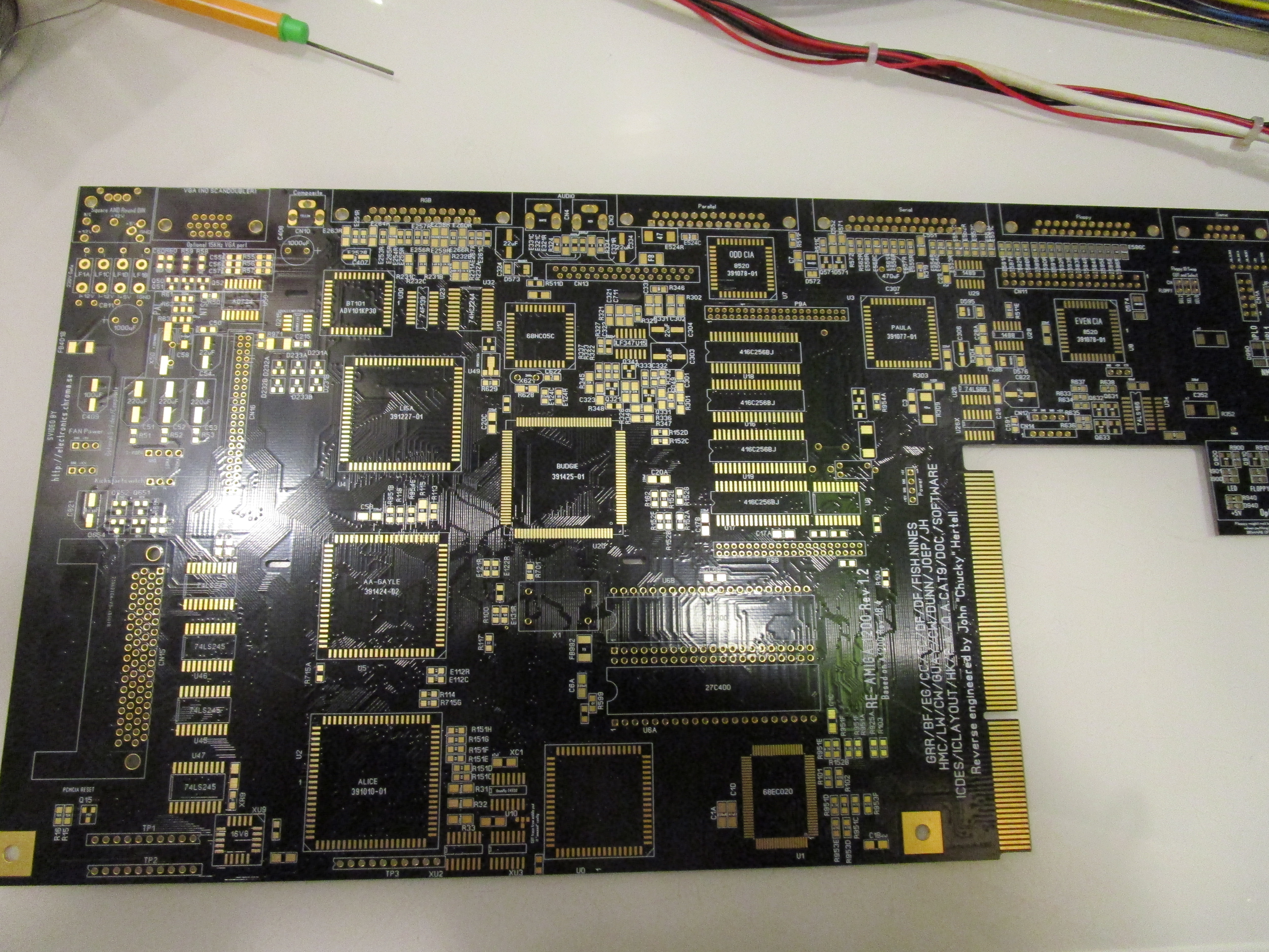
So first, I decided what board to use. And well Black is nice. so that I will use here aswell:
So first, load up the locator at http://locator.reamiga.info/locator.php?project=R1200
at Multi, choose “Resistors” and from your pile, pick up one of your packs of resistors.. like 68Ohm choose 68ohm from list:
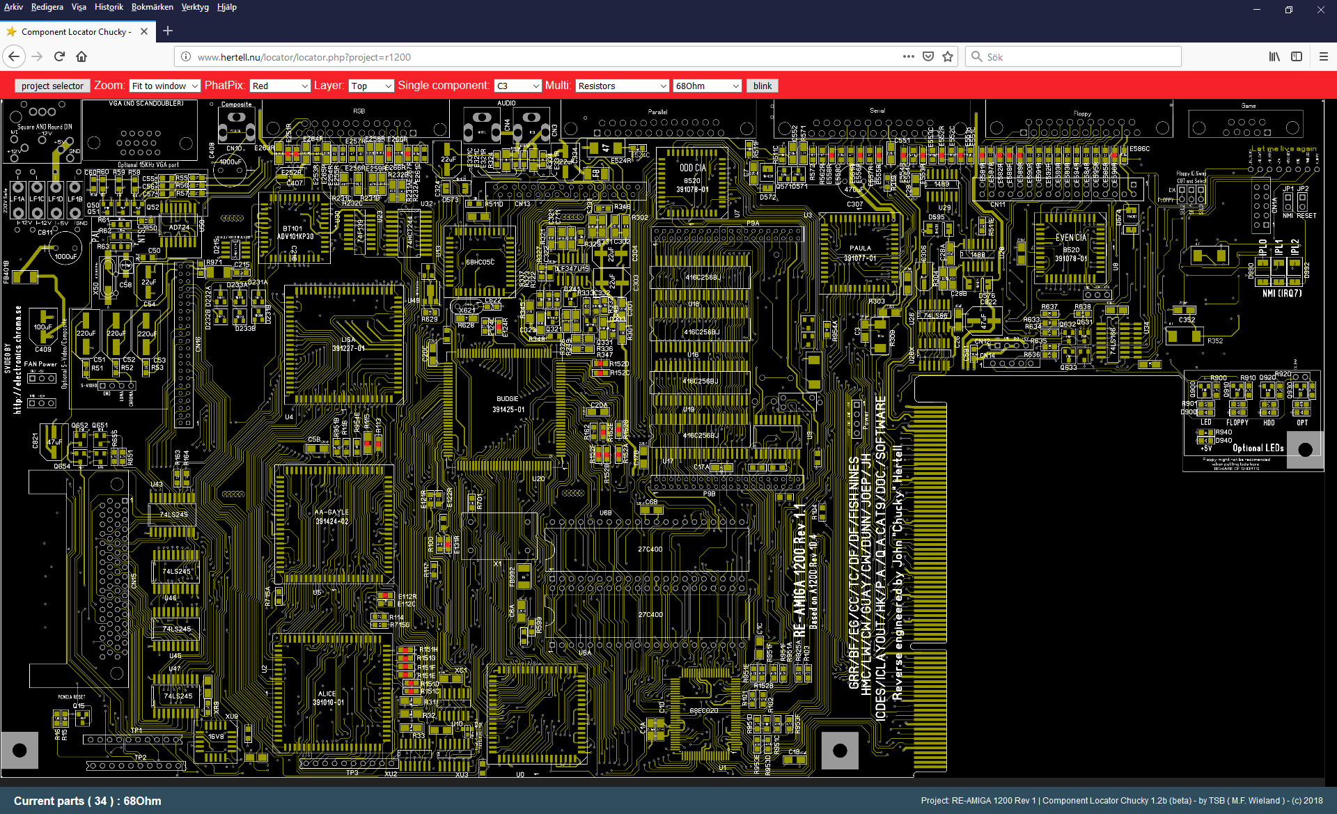
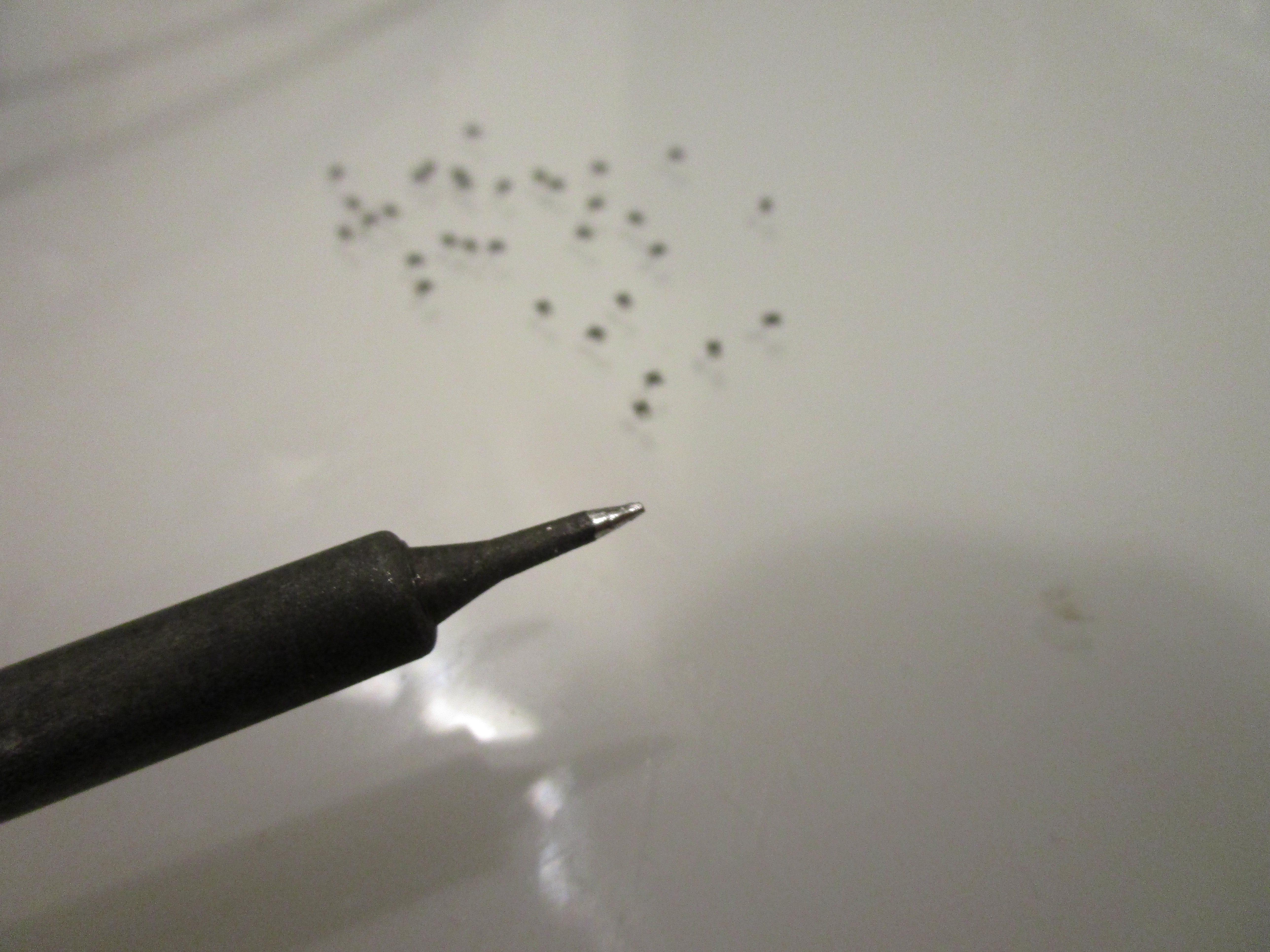
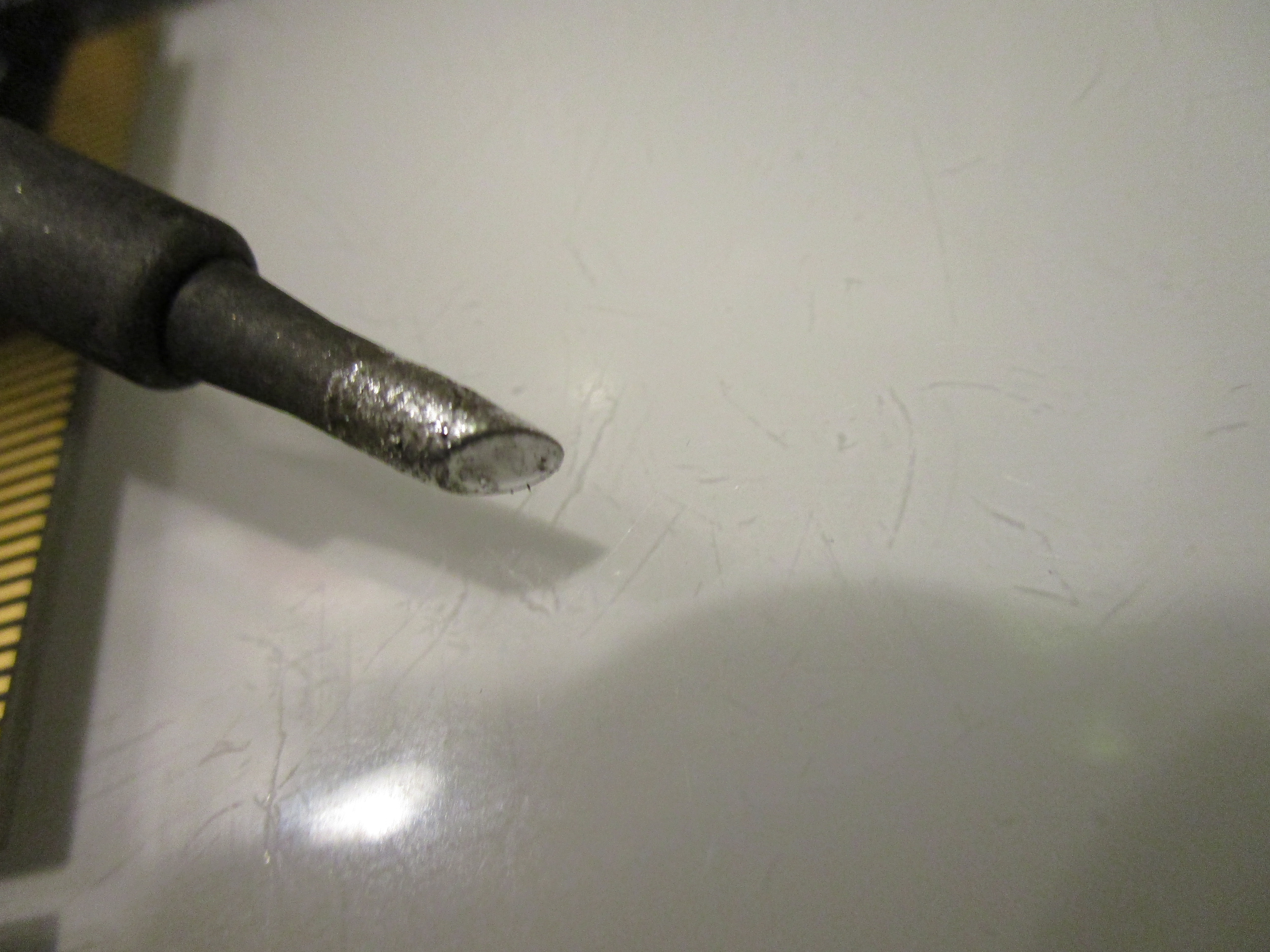
Here you can see in the lower left part that there is 34 of them on this side of the board. So I usually take out 34 of them, sort them facing up on my desk. and start soldering, with a thin tip like this:
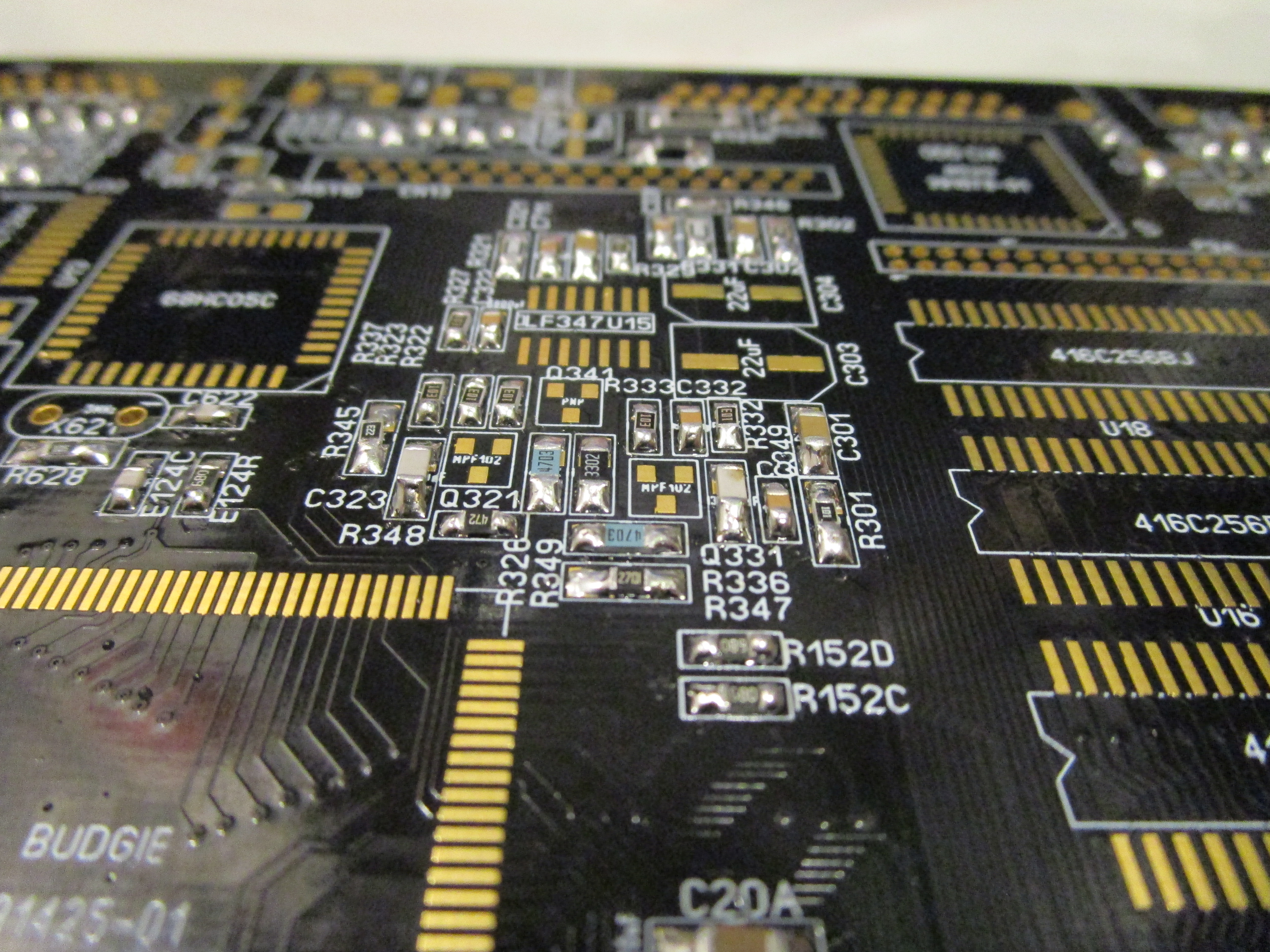
After doing all resistors on the topside, I do all caps:

And then the same thing on the bottom:

for the moment, ONLY do caps and resistors. skip diodes, transistors etc.
endresult will be something like this:
(IF you put in the diodes and transistors. it IS ok but this can be helpful if you want to learn more about the system)
Anyway. now with all the “birdseed” on place, time to get started with the real thing.
but before that. do take a look at the errata post I did: http://wordpress.hertell.nu/?p=710 as you might need to do changes on your board. I am using a rev 1.2 while doing this.
First time to start with the power:
Add the powerconnector (NOTE! ERRATA! if you have a Rev1.0 PCB. you now need to do the cutting on the trace or you will get a short)
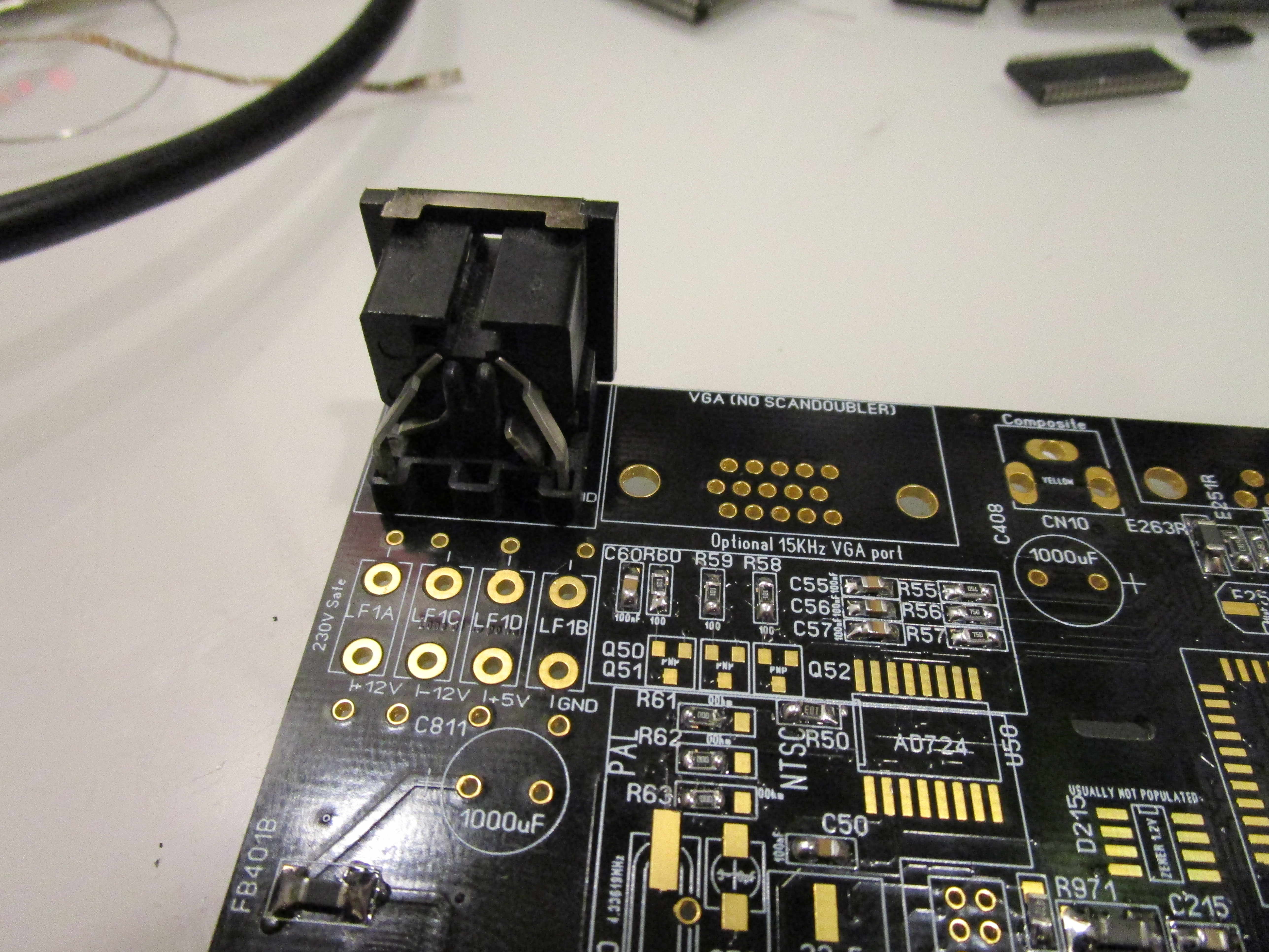
This will however not power up the PCB as you need to add the filter:

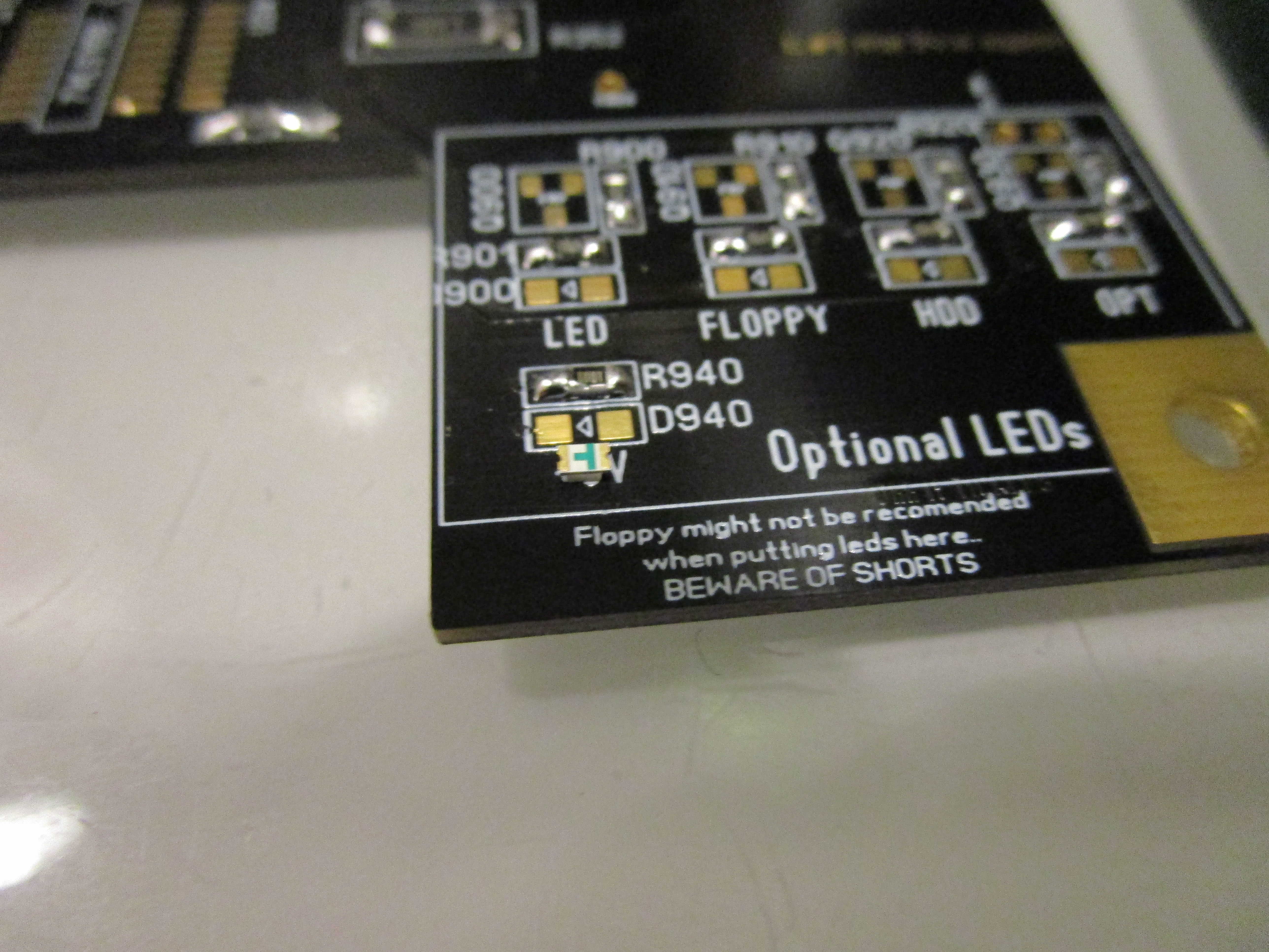
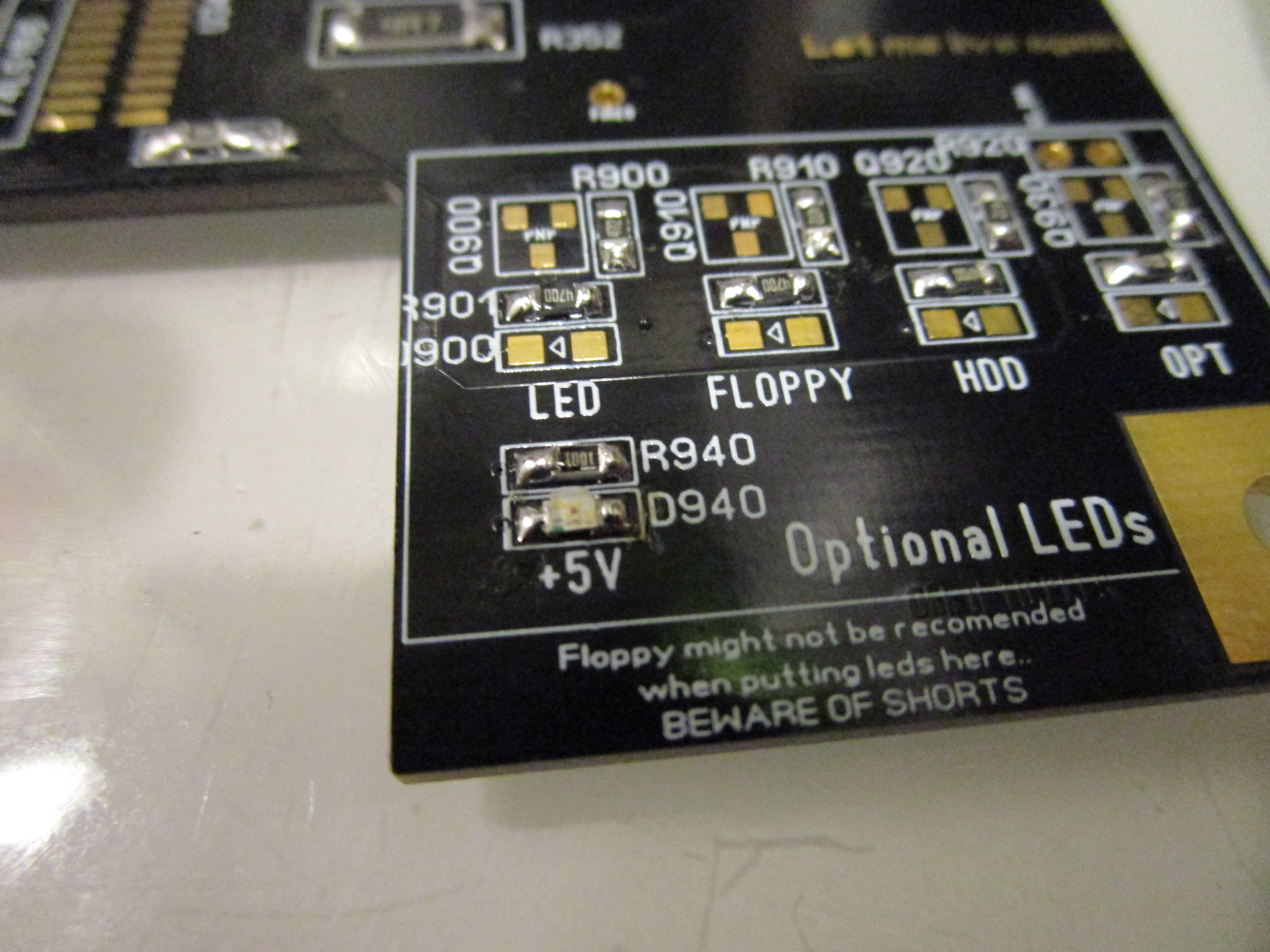
To see power lets add the LED. first picture I have turned the led upside down. so you can see the small marking facing to the left.
and the arrow on the PCB facing left. This is the direction the led should be soldered in. SOME leds have a small marking on the topside aswell.
Time to power it up:
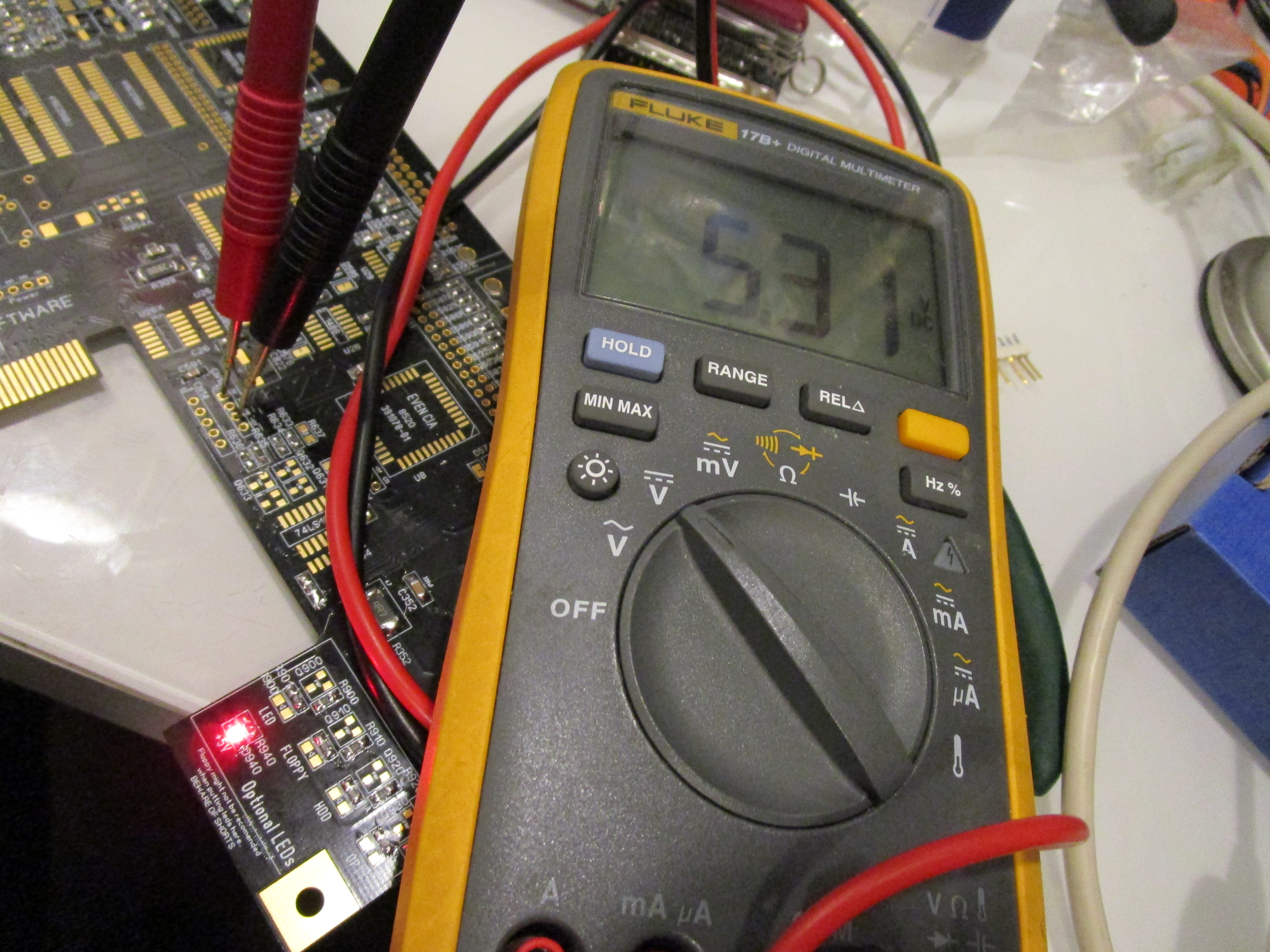
Led should be bright and you can measure the voltage on the floppy power connector. Slight overvolting is normal with no real load on the board. do not worry. -12V is located on the right part of the PAD of CAP C322 close to the powerconnector.
Now, lets add the diodes D573 etc on the board. they are there for protection and powerdistribution so lets begin with them:
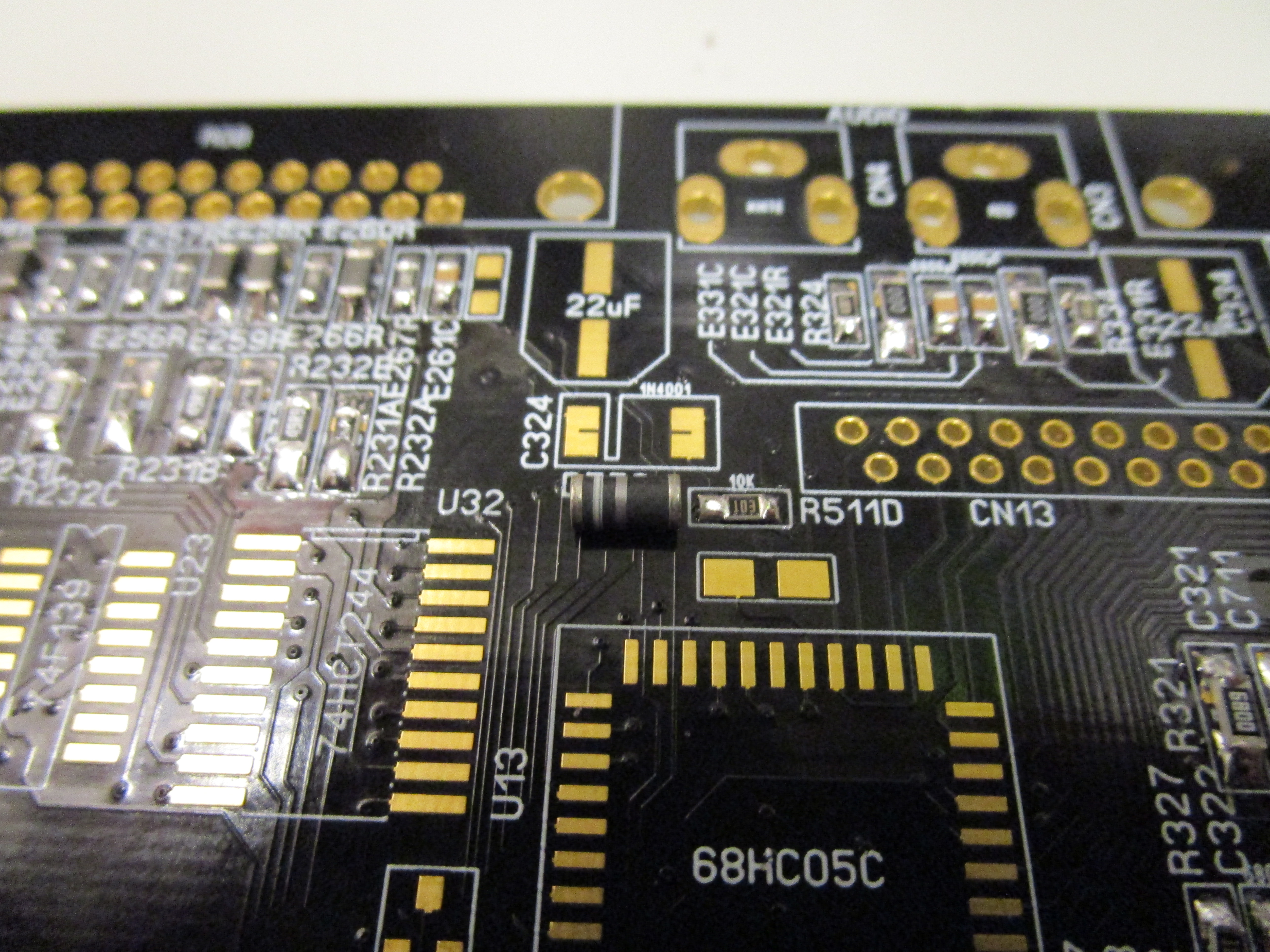
Here you can see that I have placed the diode in the direction if should be there. take a note of the silkscreen print and diode.

Solder it in. do NOT solder in the diodes at the NMI location. only the rest.
Now. add the 28MHz oscillator:
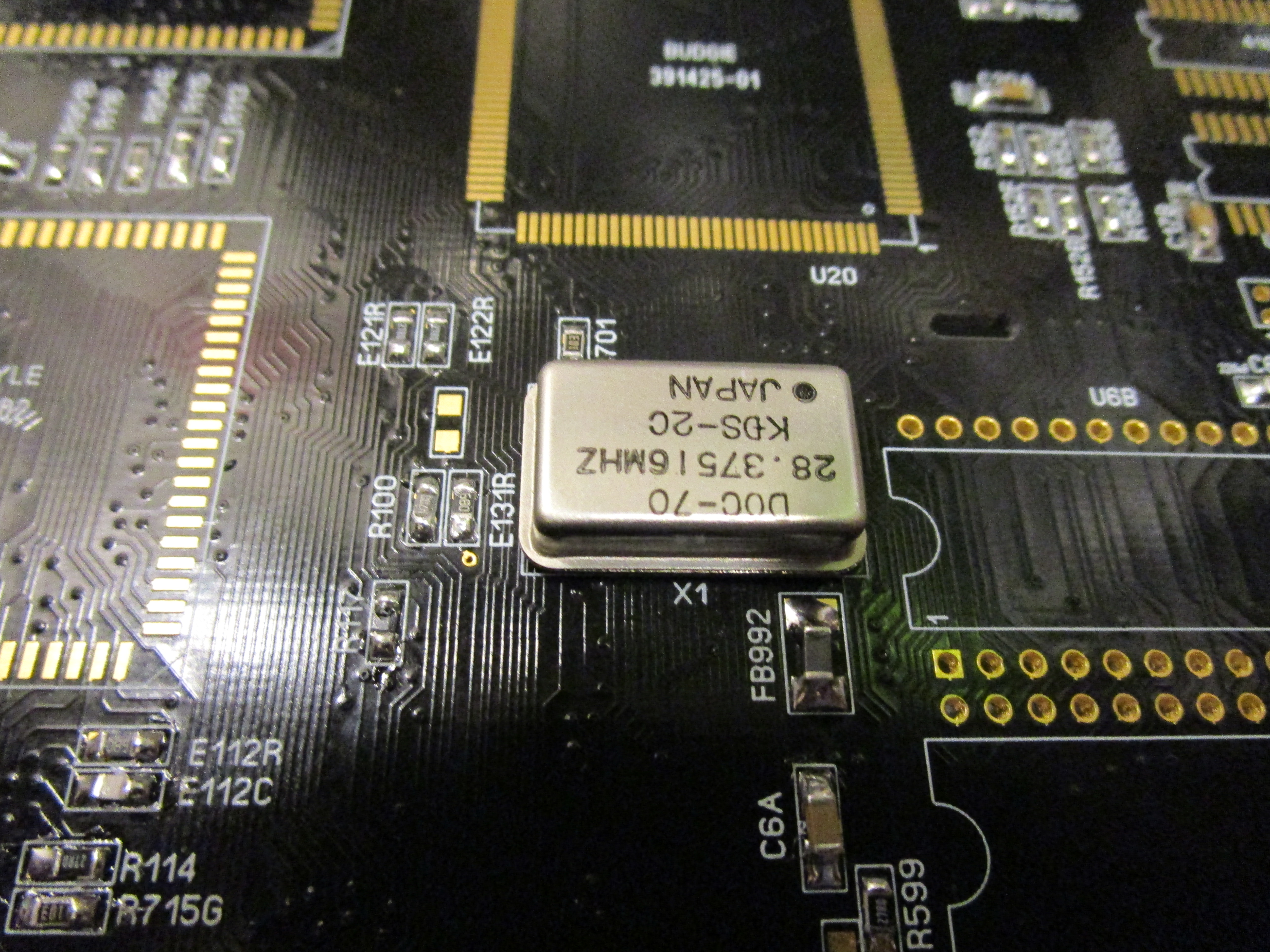
You can see that I have “forgot” to mask one via to the left of the oscillator. but no. this was not forgotten. it was a reminder that here you can probe it with your oscilloscope to see if there is a 28MHz signal here:
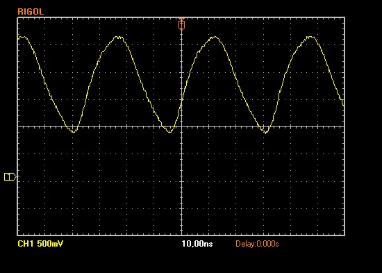
And YES. 28MHz. next step is to solder in the budgie:
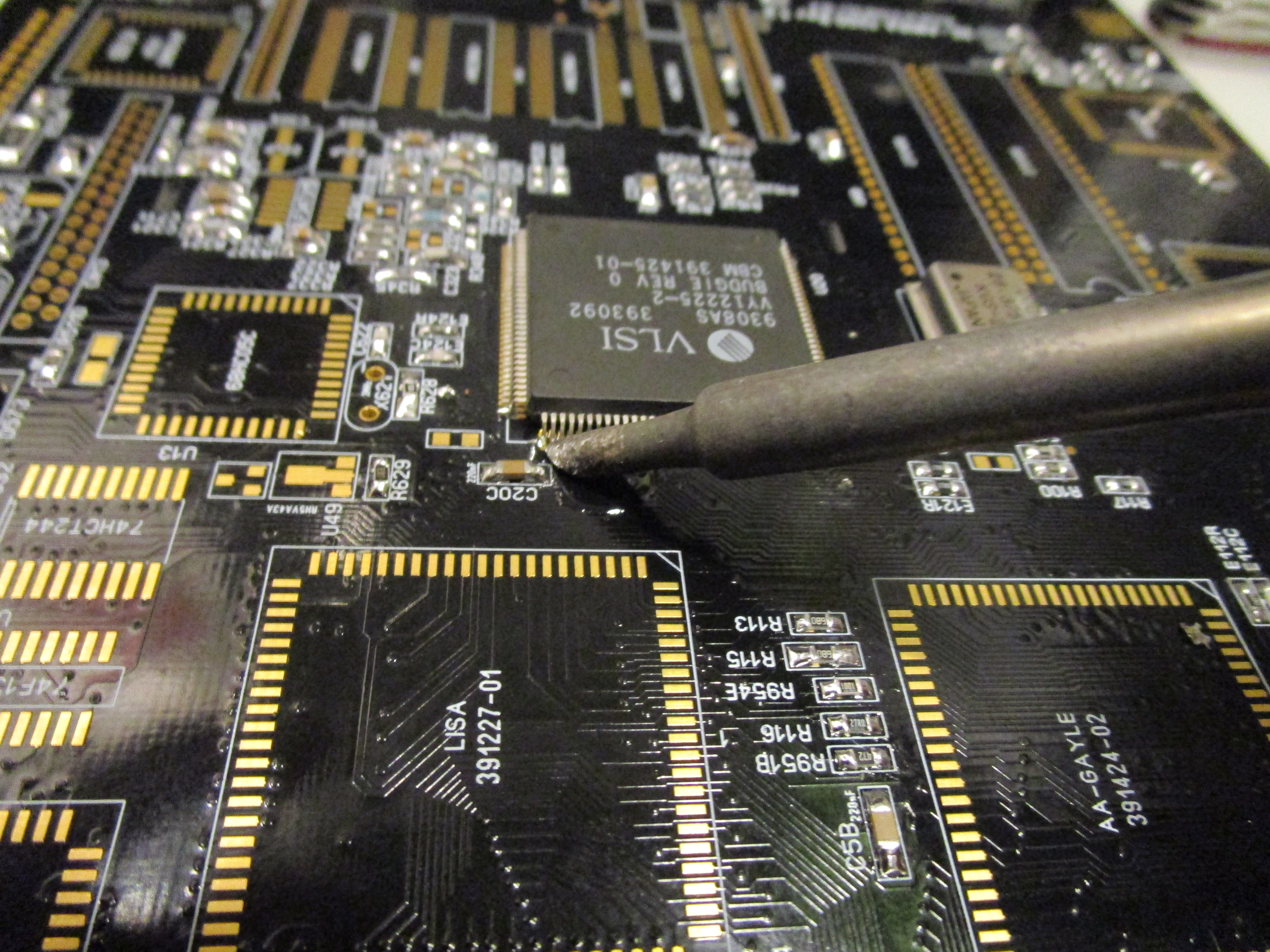
For this I use another tip on my iron that helps me do dragsoldering better:
First I put the budgie on the pads, I do a SMALL solderblob on the corner. put the budgie in place, melt the solder so it stays there. and then on the opposite side of the budgie do the same thing. checking that ALL pins seems aligned as close to the middle of all pads. also pushing down the chip as much as possible to the pcb.
Add flux:
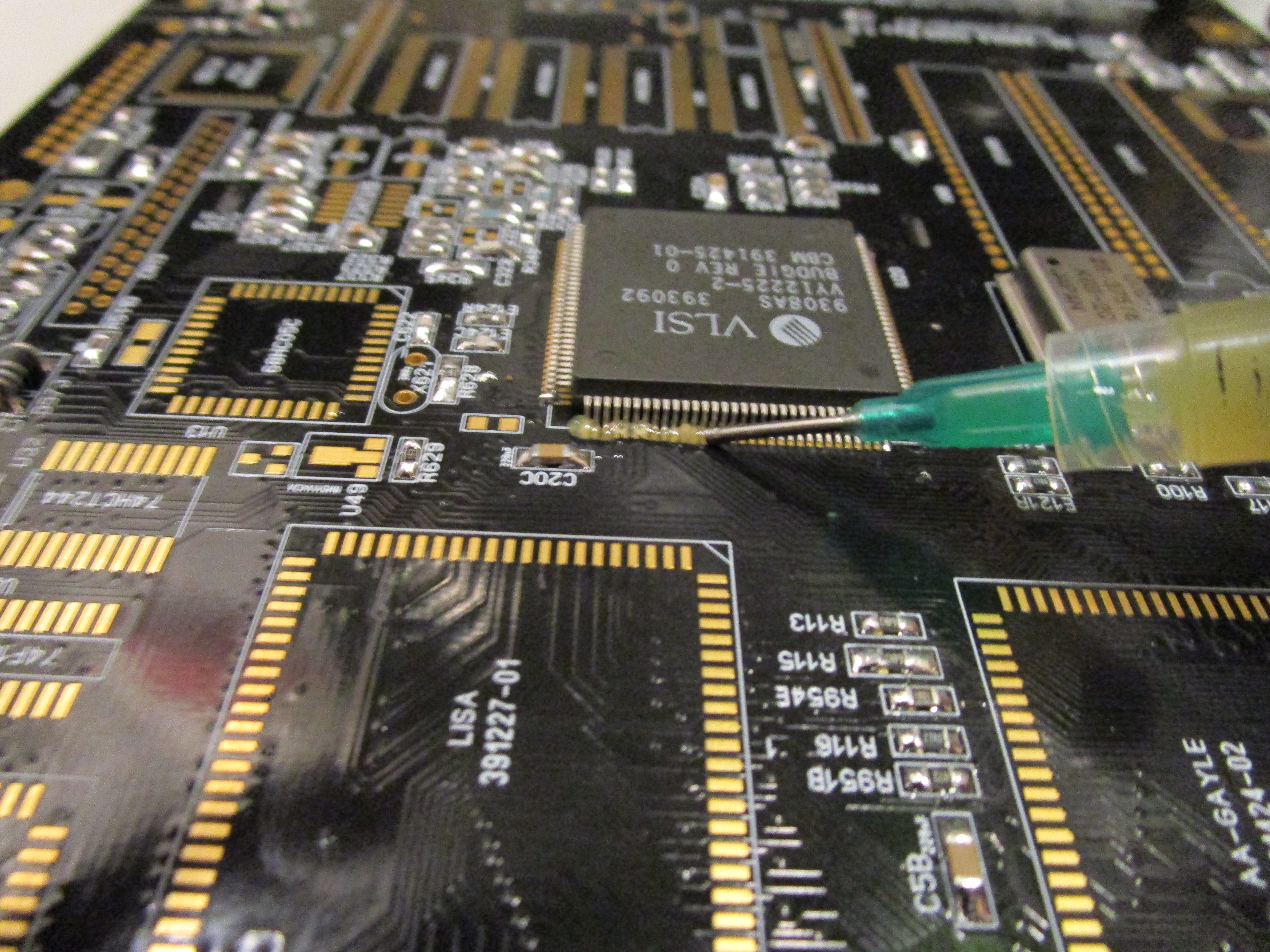
And start dragsoldering:
End result will be:
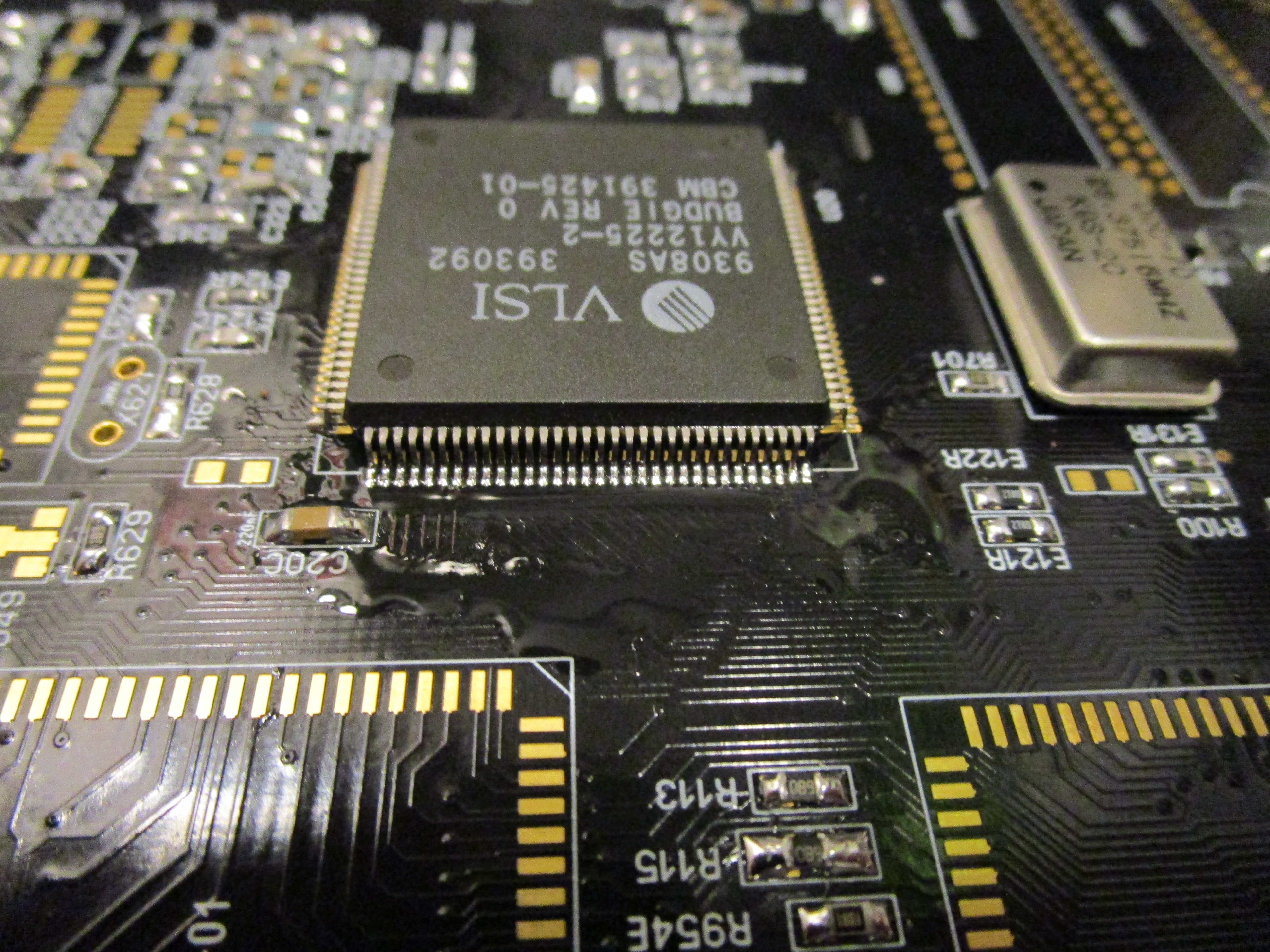
On E133R you should now have a buffered 28MHz signal from the budgie:

Now do LISA, Gayle and ALICE.
also add VGA and OR the RGB Connector for monitor (doesn’t matter what connector you do. I did both)

If you now power on your machine you SHOULD get a sync on the VGA/RGB:
IMPORTANT NOTE! If you got a rev 1.5 board you also will need to install the 74LS08 at U11 close to the videodac! This is the buffer to protect the H and V sync from ALICE.
without this. you will NOT get a H and V sync out of the ports.
also transistors Q50 – Q52 is REQUIRED on rev 1.5 board or you will not get a picture out.
OR preferbly adapt board after instructoin at: https://wordpress.hertell.nu/?p=1380
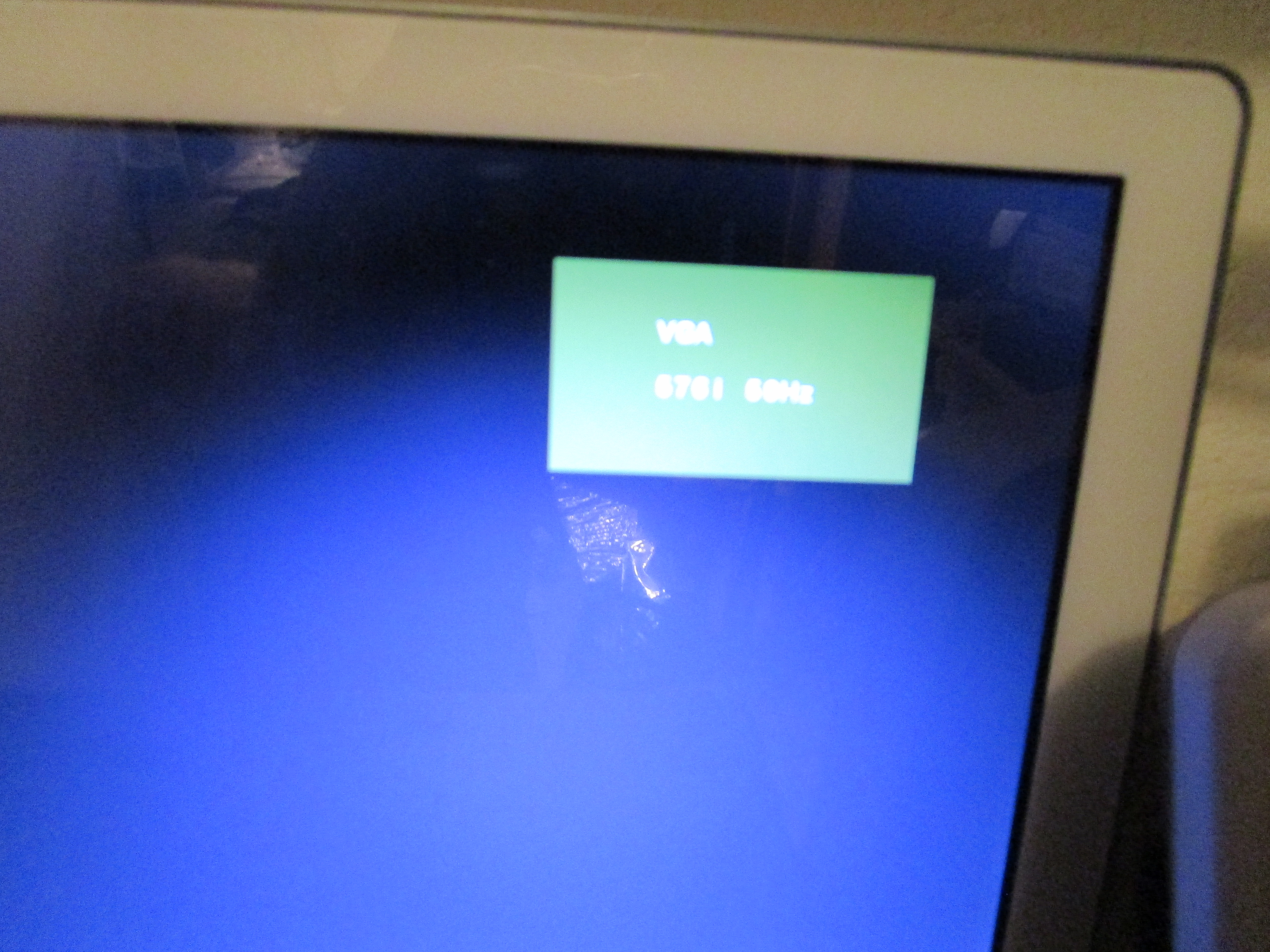
Not all monitors shows it. but mine does. you might notice it by screen go from pitch black to SOMEWHAT lighter picture.
you will NOT get any more picture or so. this is a sight that it SEEMS you have a working chipset etc.
IMPORTANT NOTE! Some boards (depending on version of chips? temeperature? whatever?) sometimes you do not get a VGA sync unless U34 is mounted! (the 74LS166 close to mouseport) so make a habit to add this chip at this point.
Chucky,
just another question:
I’m right in the middle of Part 3 now and my board is starting to come to life without any issues so far. Thank you again for this great work and even better in-depth step by step guide that really deepens my understanding of how the single parts of the machine act together.
However, regarding the birdseed, I read that bridging E127R on the back (or replacing it by a ferrite bead) prevents Alice from getting hot at high resolutions, thus preventing graphics glitches. So, do you recommend doing that?
Also, I’ve been wondering if, for a Rev. 1.2 board if using an ADV101KP30, I need to solder in C215 AND R215 or only the latter, or does the capacitor then matter at all? (I left it out until now…)
Thanks in advance,
Torsten
Ok, second question answered itself: RGB out is working without C215 if using ADV101KP30 on Rev. 1.2
Hello – Just starting out so noob question after exploring the PCB component locator, what resistance should the FB200’s have?
Thanks in advance,
–Stu
they are ferrite beads
ERRATA: Don’t you mean diode D573 instead of C324?
-Marko
Dohh 🙂
😀 (y)
Hi.
The locator does not work.
Ahh as it is moved http://locator.reamiga.info
will fix link
Thanks.
Today I finished soldering the second Reamiga.
It started the first time.
John,
the MPF102 JFET, BFR31,235 is no longer available. Would you happen to know of a direct replacement for it, or my best course of action is to desolder from the old board ?
well there are many replacements that works. I can however not give a partno now.. will be updates on the list at http://www.reamiga.info
Hi!
I seem to have problem with one of the capacitors – C3 (220nF) located below Paula chip. When I connect the board to power the the capacitor burns up. I’ve checked for shorts but can’t find any. I have installed the diodes too. Is it possible that the R308 (BIG resistor is faulty?) I have the 1.2 board version.
Edit: I replaced it three times; and the third time I installed a capacitor from original MB (i.e. I installed an 1206 cap 220nF) and then it worked. Is it possible that 0805 caps are too ‘weak’ to be used?
I also got problem with C6A cap located left to kickstart ROM.
So I’m beginning to wonder if the 0805 caps are too sensitive without any workload (components) installed.
I usually use 0805s so no that would not be the issue. unless you have caps that are 3V or so.. you must have 16V or more..
Ok I understand.. Thank’s!!
Hey Chucky,
Just finished putting all bird seed on the board (1.5 rev) and realized there are in fact two 33K resistors, not one. There is one on each side. Could you please update the list on your other page to reflect this? (Normally I change single items into 10 when ordering, but somehow I didn’t for this resistor – doh!)
yeah I will need to remember to fix that 🙂
I have recently populated a 1.5 board according to the steps provided in this blog. I have installed caps and resistors, installed budgie and oscillator. If I power the board, the power light lights up and I get a 28 mhz signal from the oscillator. But the value at resistor E122R is high, not giving a pulse. What could it be?
Hello Chucky,
Most of the components i could order by Digi-Key…but there a couple of components that i have to order 5000pcs while i only need one or two.
ERJ-6RED1004V and APC805B2K00N. That’s a bit pricey for me 😉
And the components below are not beind made anymore, do you have alternatives for them; BF861b,235 and EFO-MN3004a4.
BC856AT i cannot order form Digi-Key because of a very long wailtinglist.
Any suggestions…it’a for ReAmiga 1.5 board…Thx in advance
put the partno in mouser/digikey click to find alternatve and click as many options as possible. you usually find an anlternative
Hi Chucky,
Thank you for all your work on ReAmiga. I’m in the process of building a ReAmiga 1200.
I managed to complete Part 1 (or so I thought)
28MHz signal is fine
I tested using an oscilloscope for VSYNC and HSYNC which I could see, and proceeded to Part 2.
But at the stage in Part 2 where you use a CPU card (in my case Turbo 1230-MK2) I wasn’t getting the LED activity. So I started to back-track and this is where I noticed I didn’t have VSYNC / HSYNC.
I have reverted almost back to the end of Part 1, assuming something was causing the missing video signal. However after more testing I have noticed that VSYNC and HSYNC don’t tend to appear from a boot ‘after being left for some time’.
If I power on, no signal, power off then back on and suddenly a signal appears (pretty much all of the time after it has had some power through it on the first attempt).
Any idea what might be causing this really strange behaviour? I have gone over the joints for Budgie, Gayle, Lisa, and Alice many times and they seem to be soldered just fine.
I’m guessing its not normal to boot with no sync signal at times?
Thank you
maybe you missed the part of U34 that is added later it needs to be installed
Thanks for the quick response, I can confirm U34 installed (LS166A).
I have tried timing things, here are my obserations:
After 6 – 10 seconds “without power”: power on, and the video sync signals are just high.
from a power on state: power off, and back on within 5 seconds and the correct video signals are present.
I have applied heat to the board and the behaviour remains the same, as I was thinking something might be working only when its warmed up a bit.
I’m wondering if one of the amiga chips is only working marginal or something
Hi again Chucky,
I have found that when I power on from cold (as in no power for over 10 seconds) the video signal is consistently high. However, when I briefly ground the reset signal on LISA (pin 9) the signal becomes present.
Am I over thinking things? When I get the reset circuit in maybe this will no longer be an issue?
sorry I meant pin 24 on LISA, not pin 9 (I was counting 9 down from a reference point).
I can also briefly ground R116 pin 1 (RESET) and it kicks the video signal on too
Hey Chucky, sorry for the amount of messages.
My instincts pointed to the issue being GAYLE, since apparently I wasn’t getting reset signal either (I figured the reset signal might have corrected video sync).
I have now swapped GALYE and now everything is as it should be (finally).
I believe this might have been the issue with the old board all along, oh well!
On to next steps…