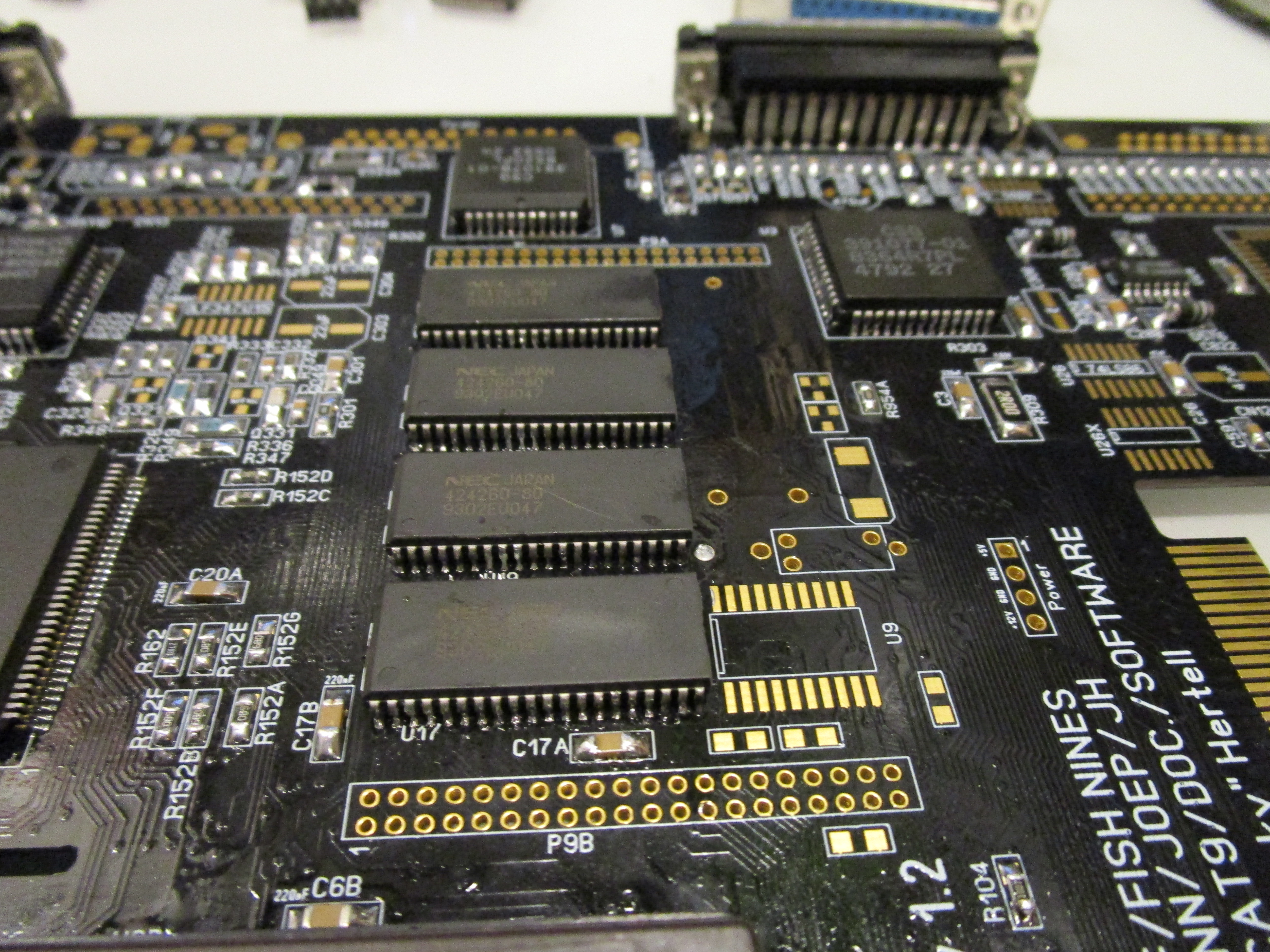
So lets add memory. This is also a quite tricky part of the ReAmiga project as the distance between the chips is making it harder to handsolder.
This is how I am doing it:
First I tin all pads:
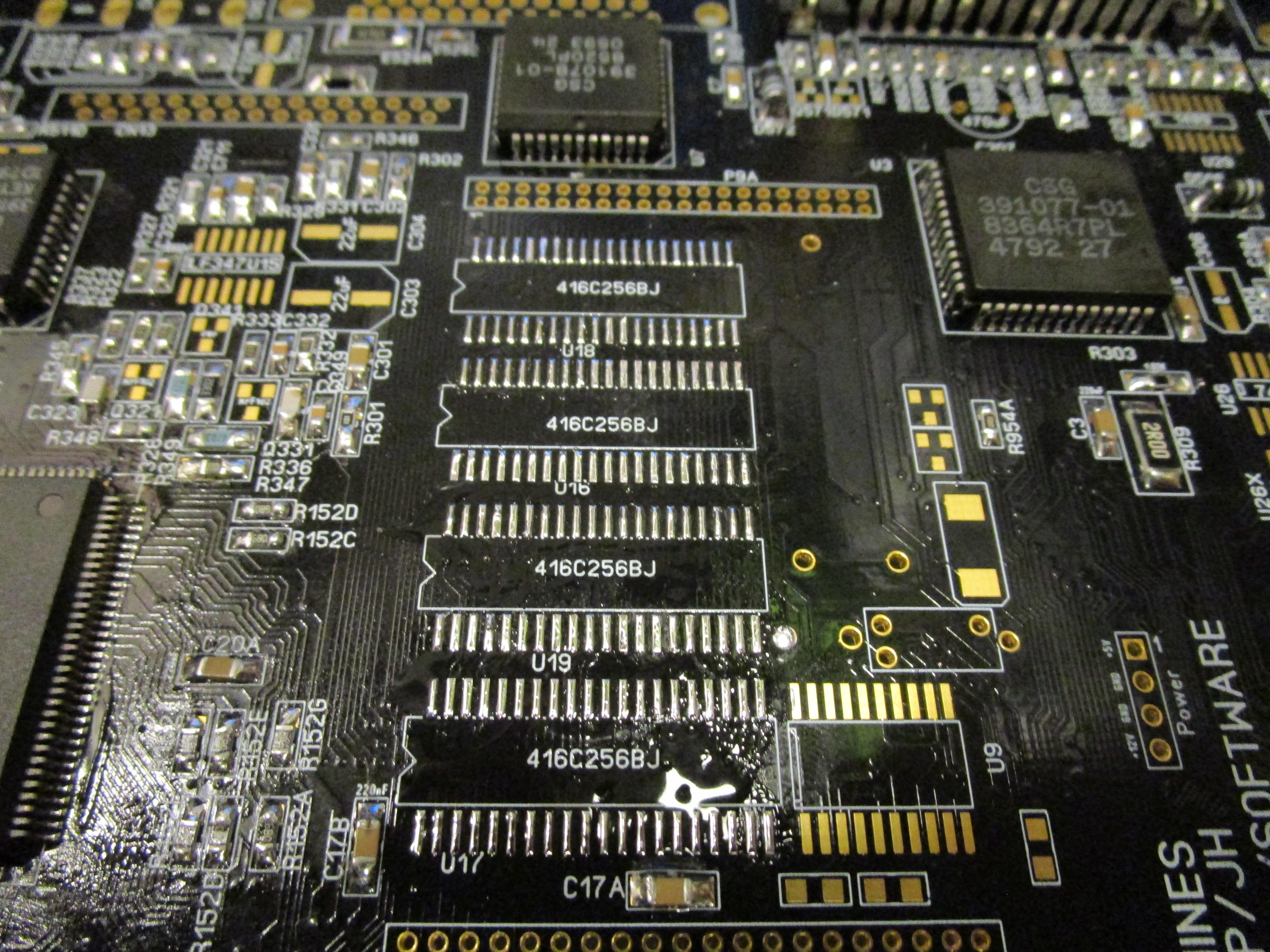
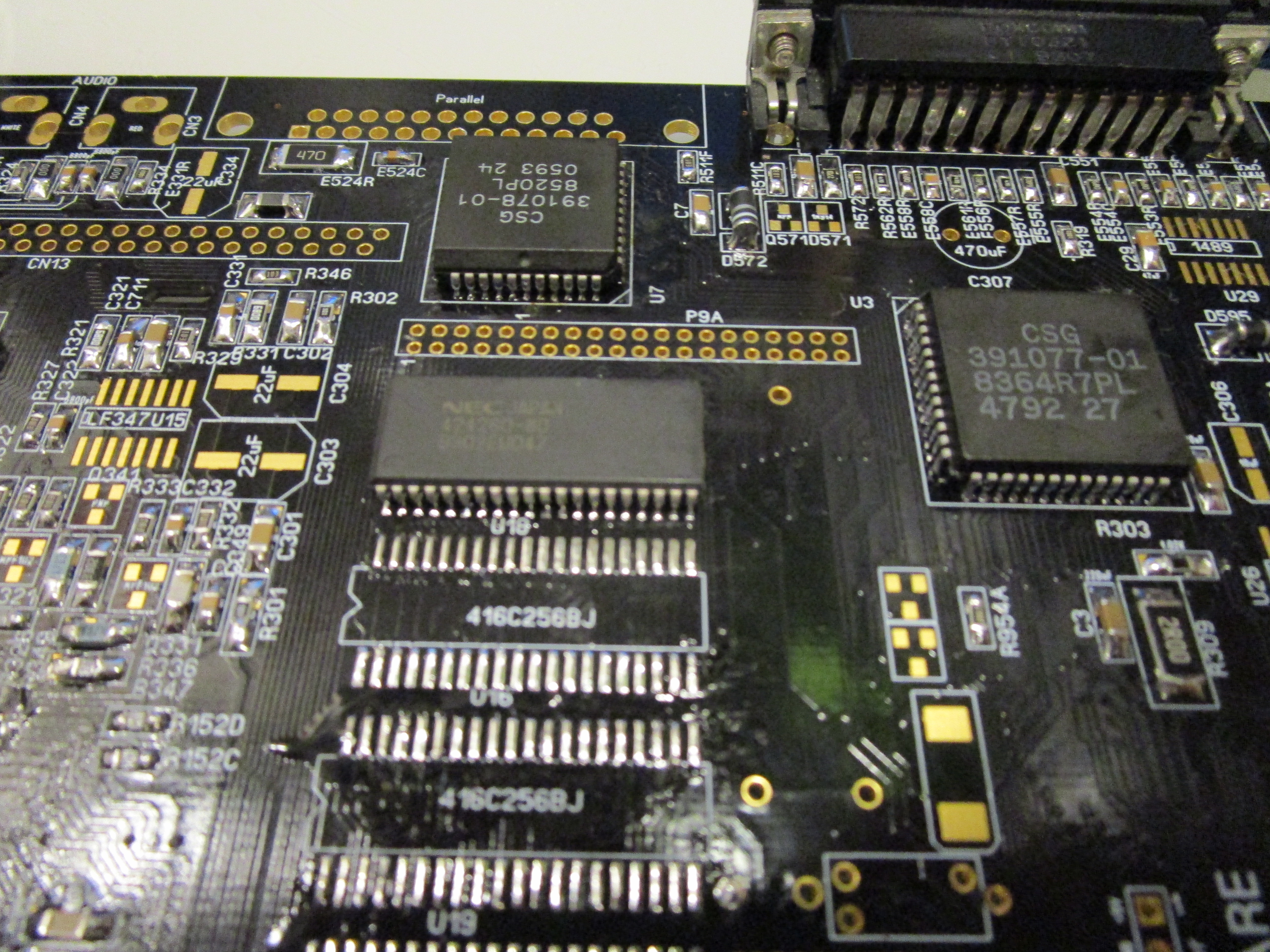
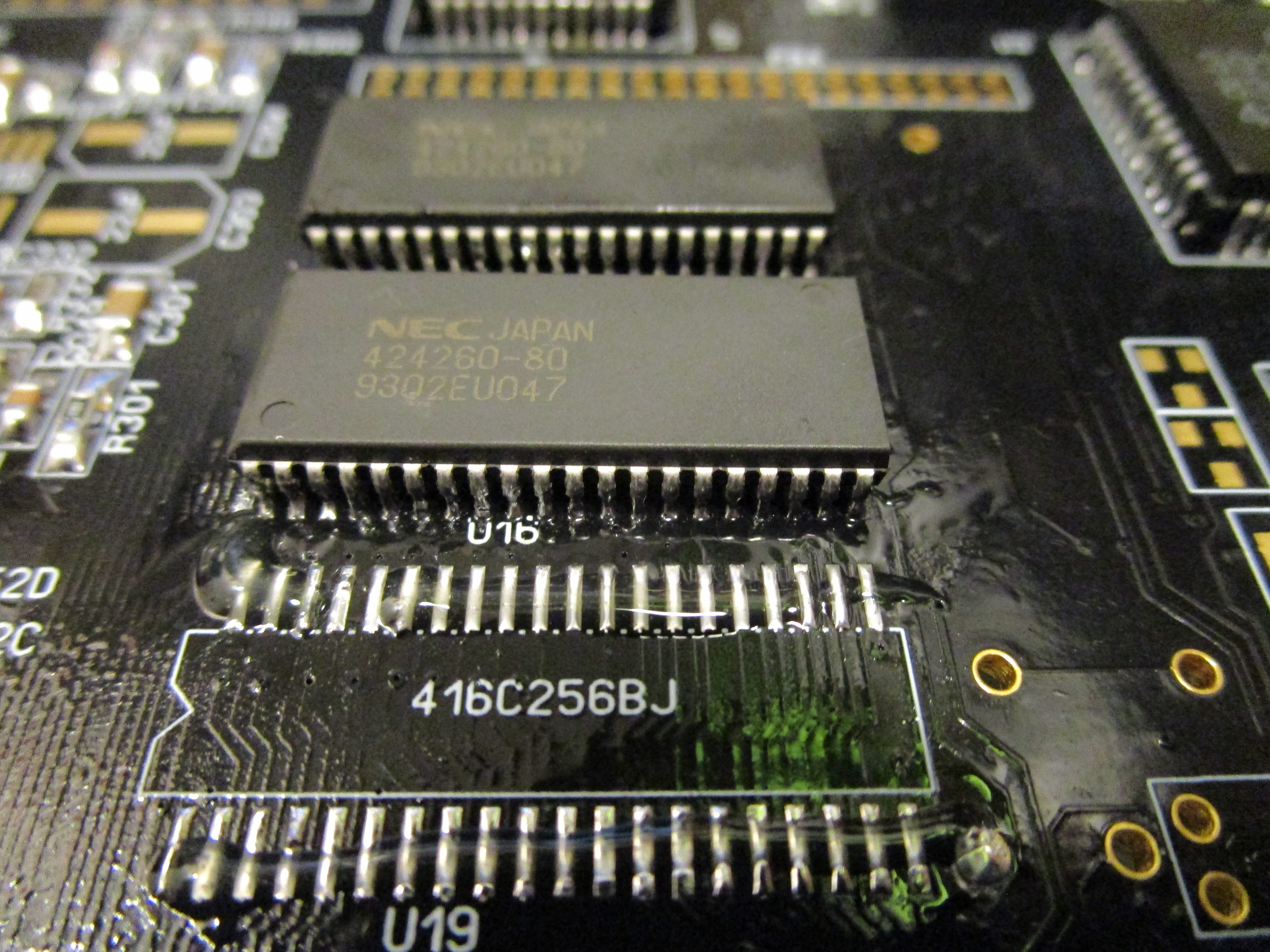
Add flux ontop of it and put a memorychip on U18 (thats the location of the top).
and heat it up from above with hot air:

Sometime I use a tool to push down the chip. when you see the chip settle, stop the heating to avoid warping of the pcb.
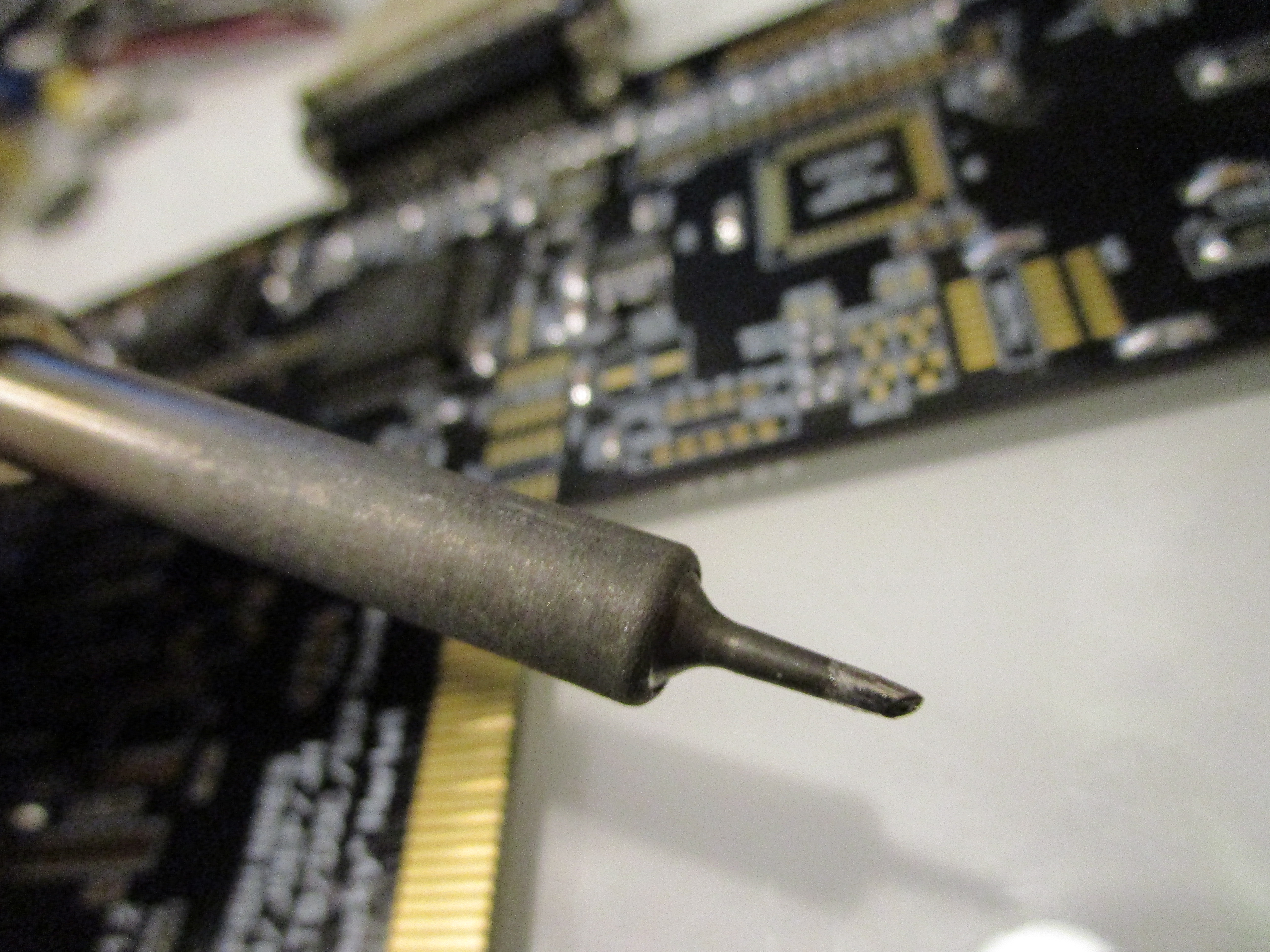
Usually I add extra solder, using this type of tip:
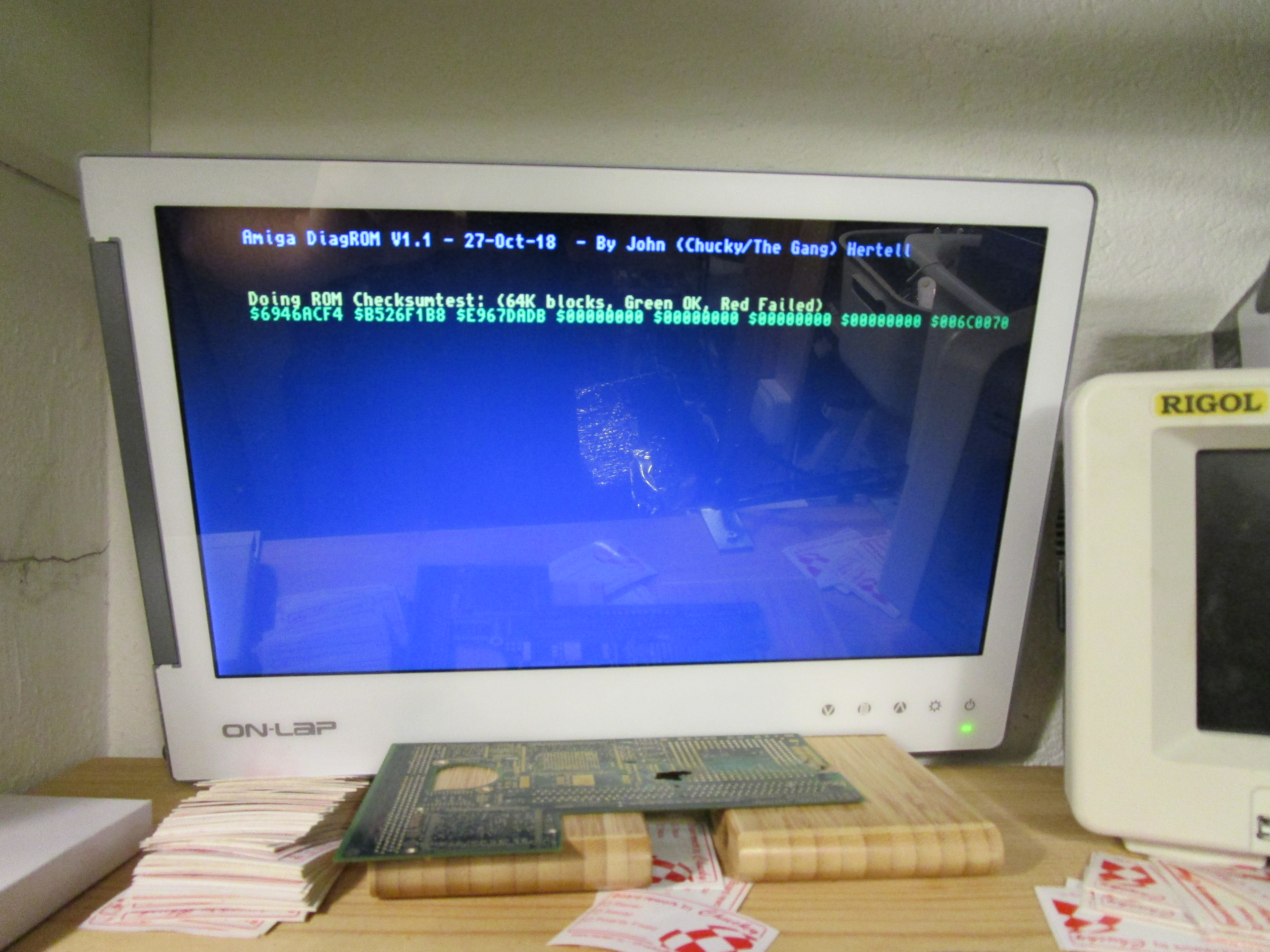
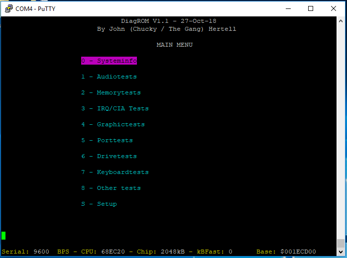
When this is done. Start the machine and look at the DiagROM output:
After $100000 look at the first 4 chars in the hexadecimal code. It should be the same as what it is written. Marked in the picture above.
if this is ok, then U18 is ok and soldered in ok
Now do the same with U16: (4 first chars BEFORE $100000)
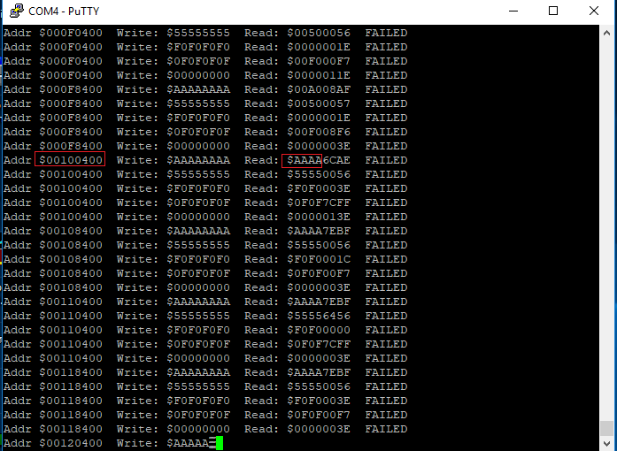
and check DiagROM again:
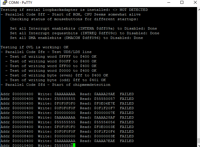
First 4 bytes is the interesting part now. and as you can see here there is an issue.
Look where it shold be $f0f0 it reads $f0e0. and where it should be $0f0f it reads $0f1f.
doing a check of soldering and fill up some:

THATs better. remember sometimes a bridge here with memory can make machine not start at all. (also a reason why I do this in parts like this. then we know WHERE the reason for nostart is)
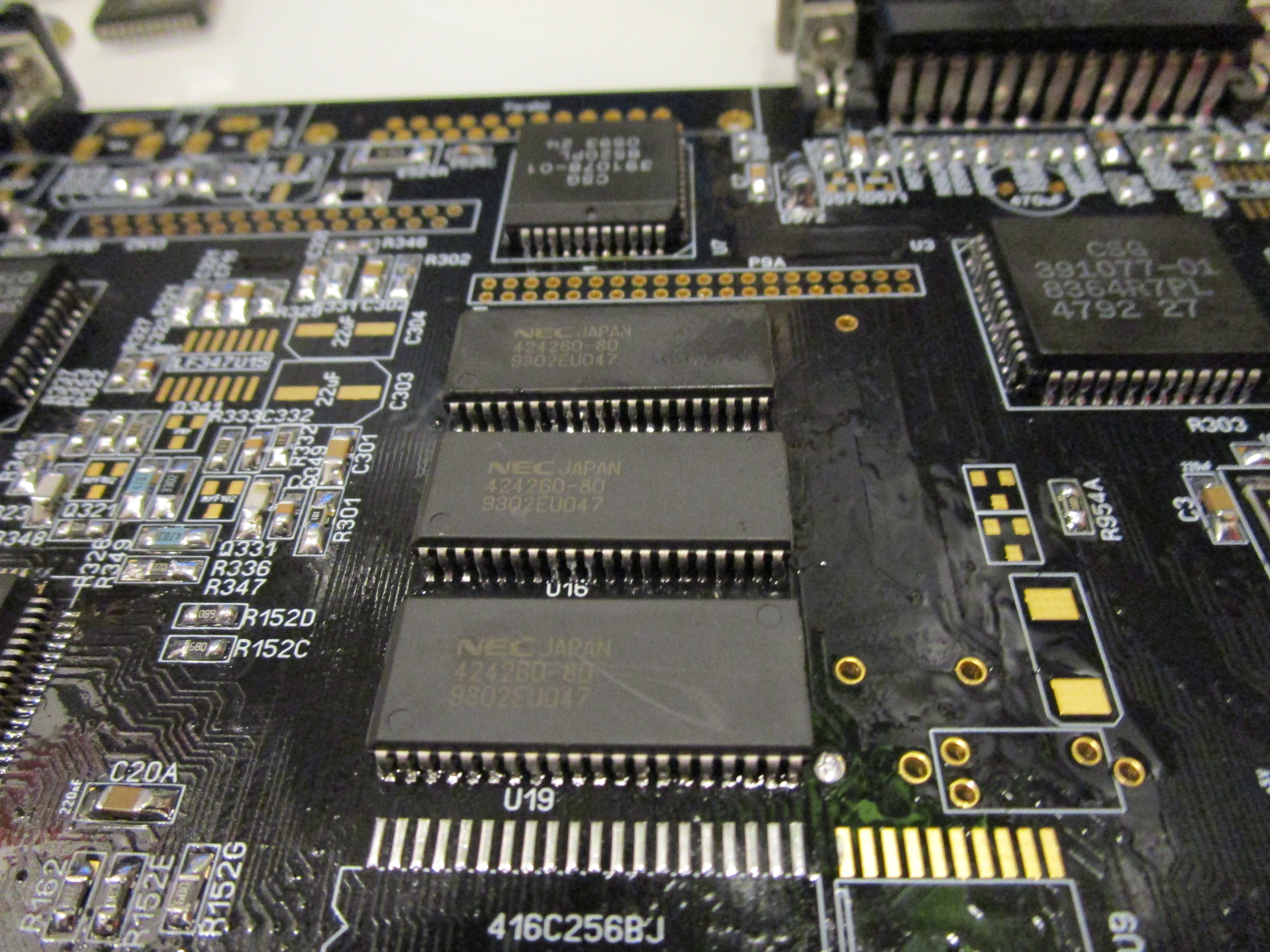
Lets do U19: (4 last chars after $100000)
And DiagROM should say:
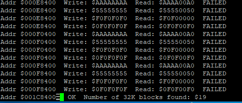
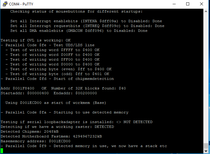
Now after $100000 you will hopefully notice that it starts to count up OK blocks.
Lets do the last memorychip now. U17: (last 4 chars before $100000)
And check DiagROM:
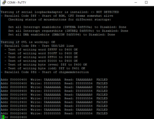
Oh. something looks bad.
Checking soldering, found a bridge
now it would be interesting to have something shown on the screen.
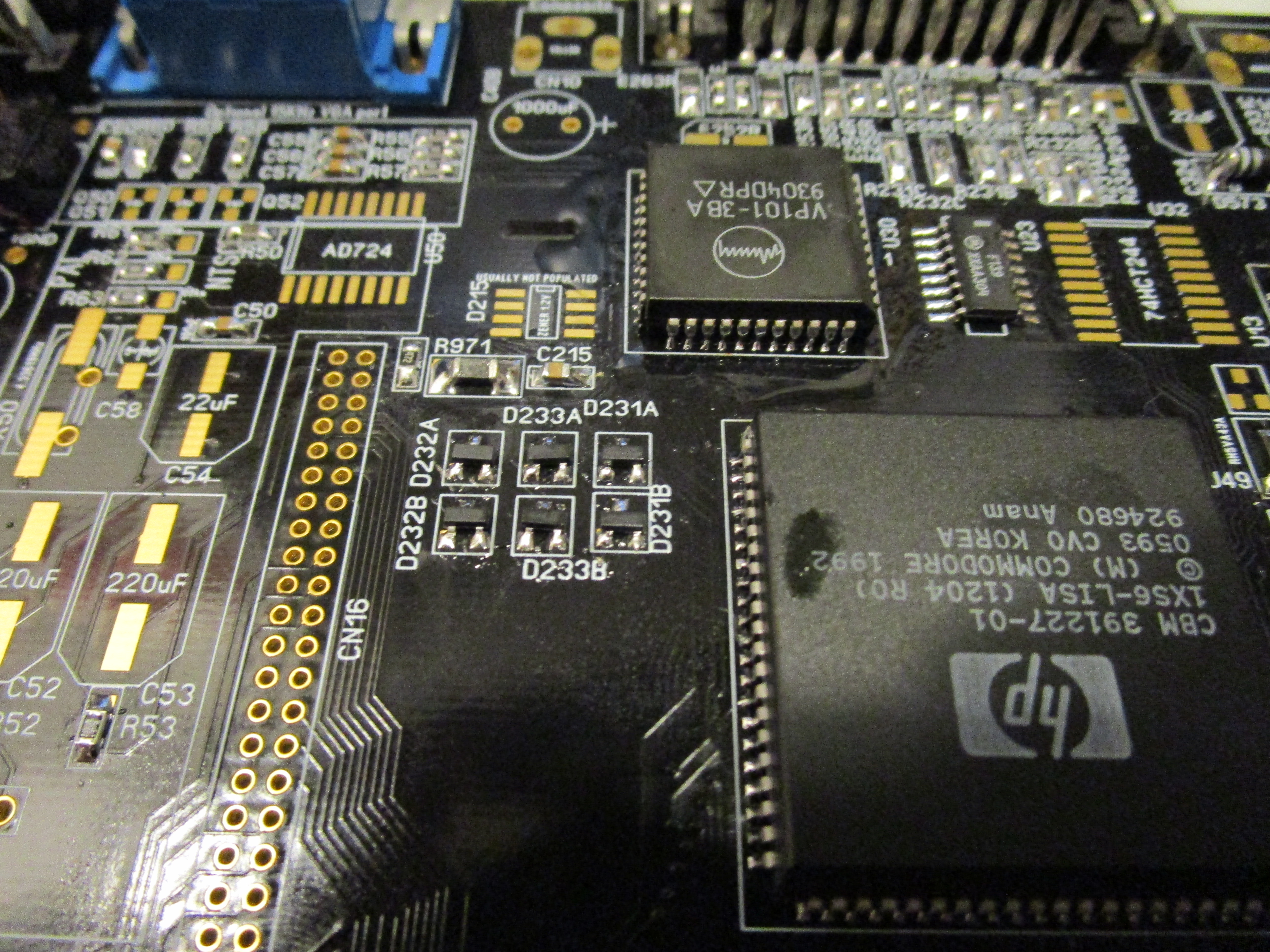
Lets add the videoDAC:
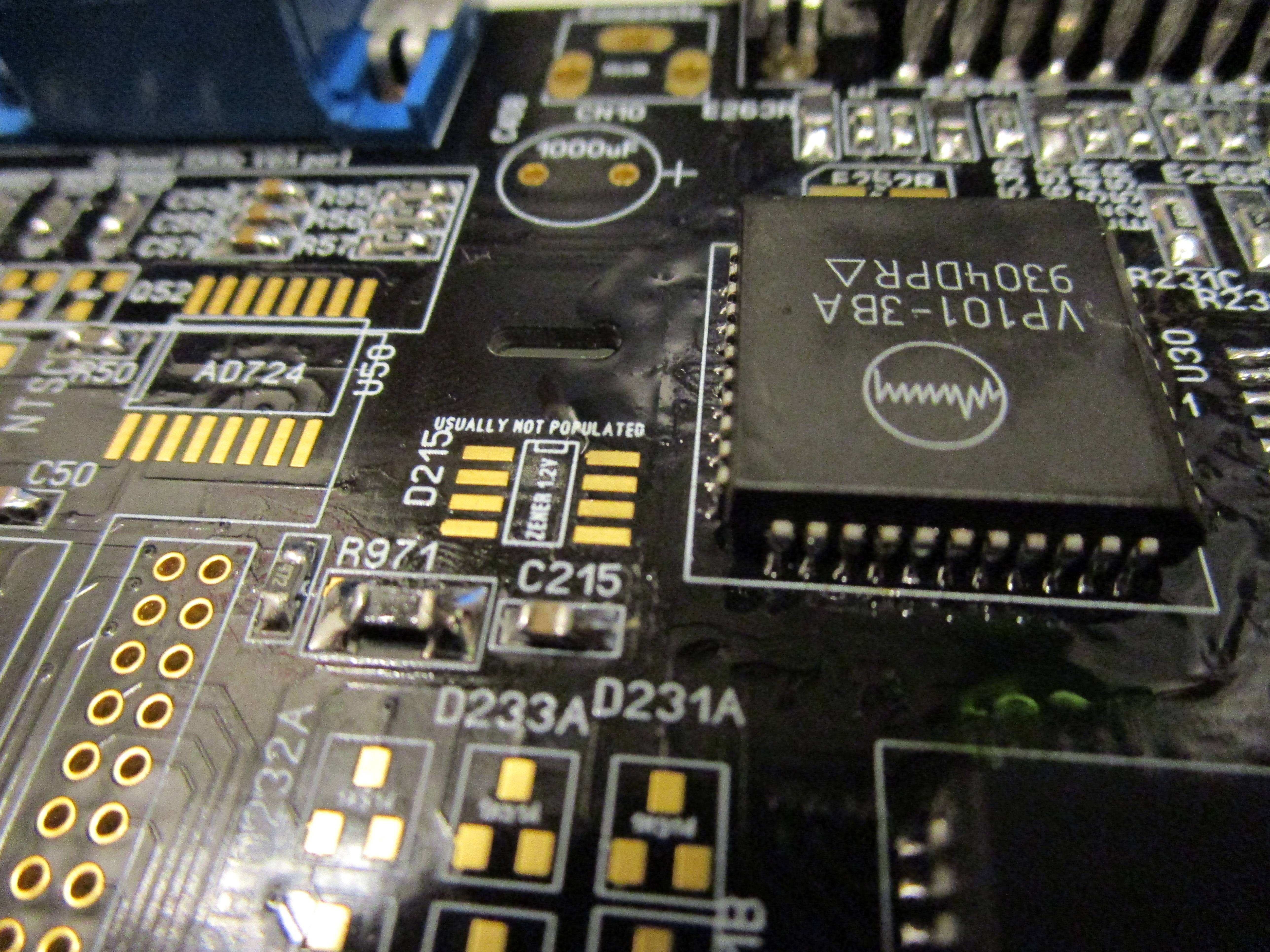
This is the VP101. if you are using the ADV101 you will also need to populate the D215 with a zenerdiode.
(wording zenerdiode is from schematics it is a LM385-1-2)
and Rev 1.2 on the bottom side under the VideoDAC:
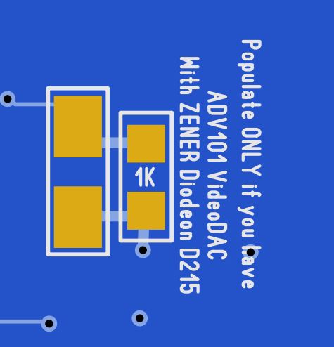
Add a 1K resistor there. if you have a rev below 1.2 you need to put a resistor on the right pad of C215 (and skip the capacitor..) pointing down and put a jumperwire from other end of resistor to the top pin of D233A or D231A.
Lets go on.
Also add a 74139 at U23:

now you will get a picture on the RGB port. the diodes should be needed. I need to investigate if they can be skipped. but lets put them there anyway:
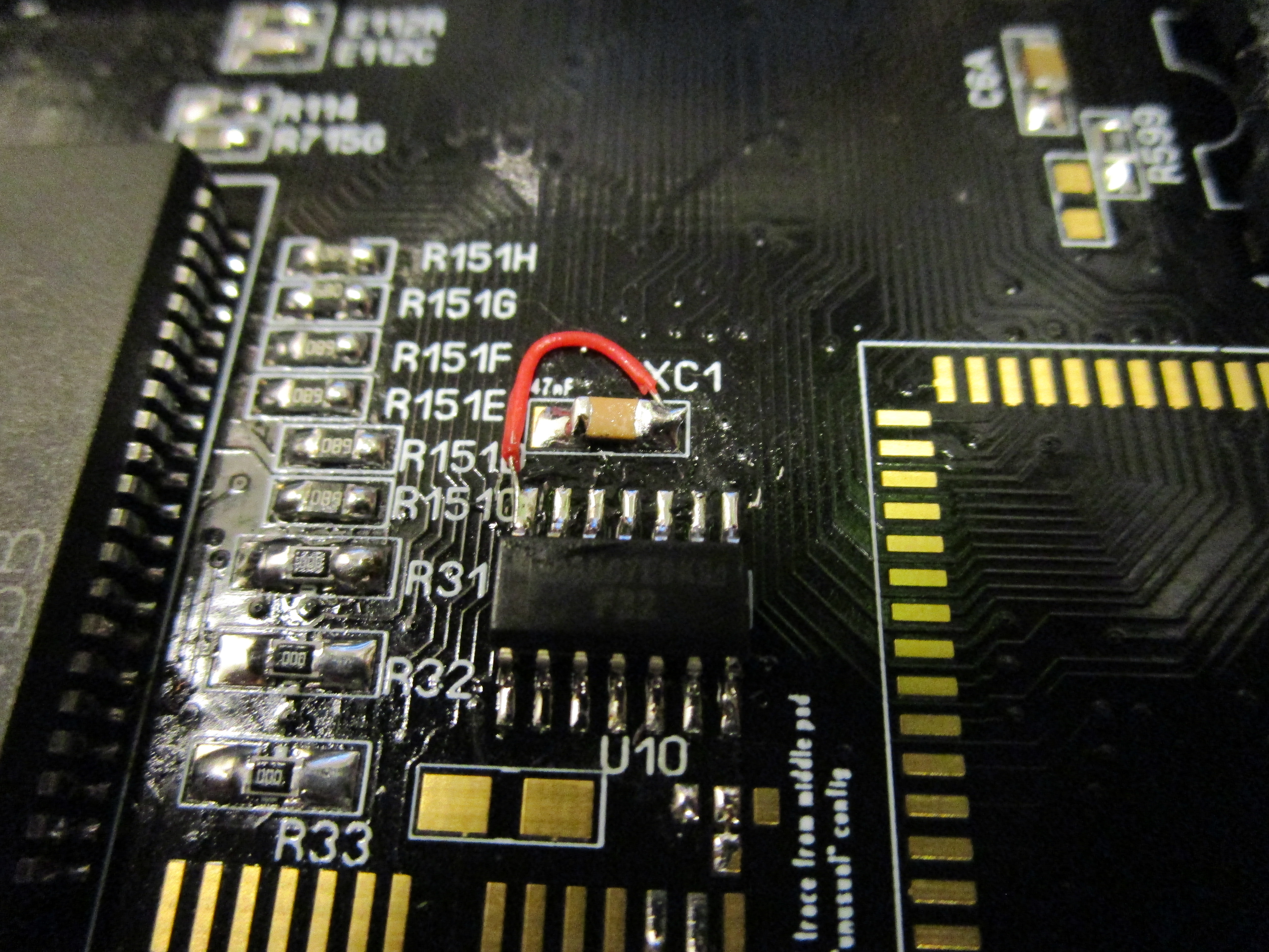
SOME machines can get an issue with diagrom just showing the screenflashing but no picture. then a 74F32 will be needed at U10. (some Amigas had a 74HCT08 here. not checked if that will work aswell) but. also very strange that it seems to be working anyway. even if that chip doesn’t get any power. so I add a jumpercable to make sure it gets power (and not so much magic involved):
On boards 1.2 and above this chip can be skipped
also on boards BELOW Rev 1.2 you will need a solderblob:
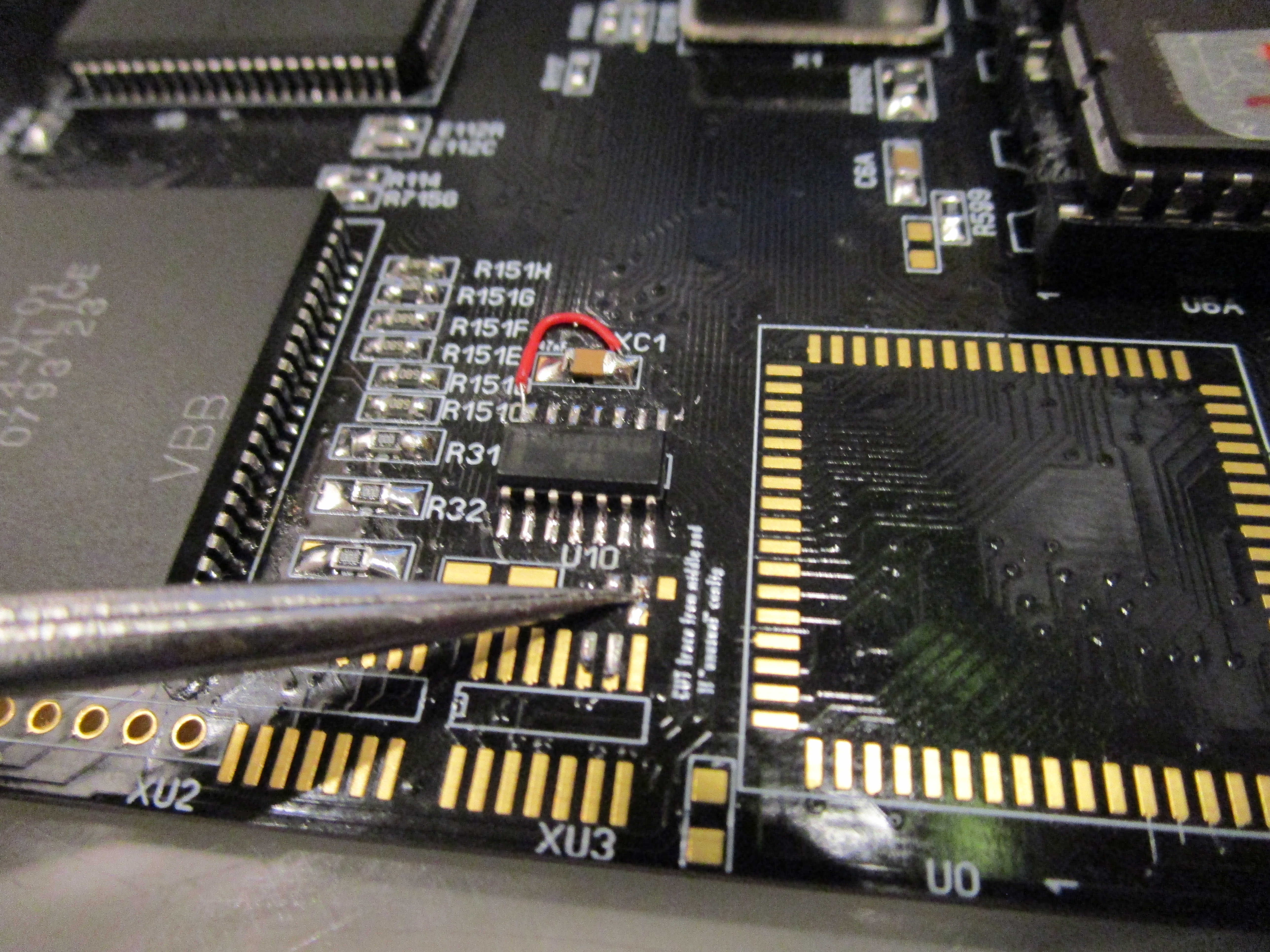
Between the middle pad and the bottom pad. on rev 1.2 this is not needed as there is a trace going there. but if you have rev 1.1. put a blob there. on rev 1.0 you will need a small wire from middle pad to the bottom pad (that is not located below but to the right bottom)
to get picture out on the VGA connector you need to add 3 PNP transistors:

if you decided to NOT use the VGA connector and also skip composite/svideo. you do not need this. then you could also remove all components in that square. as they unfortunally will make the Amiga RGB picture slightly darker. if you will use Composite/Svideo this must be populated (except the VGA connector)
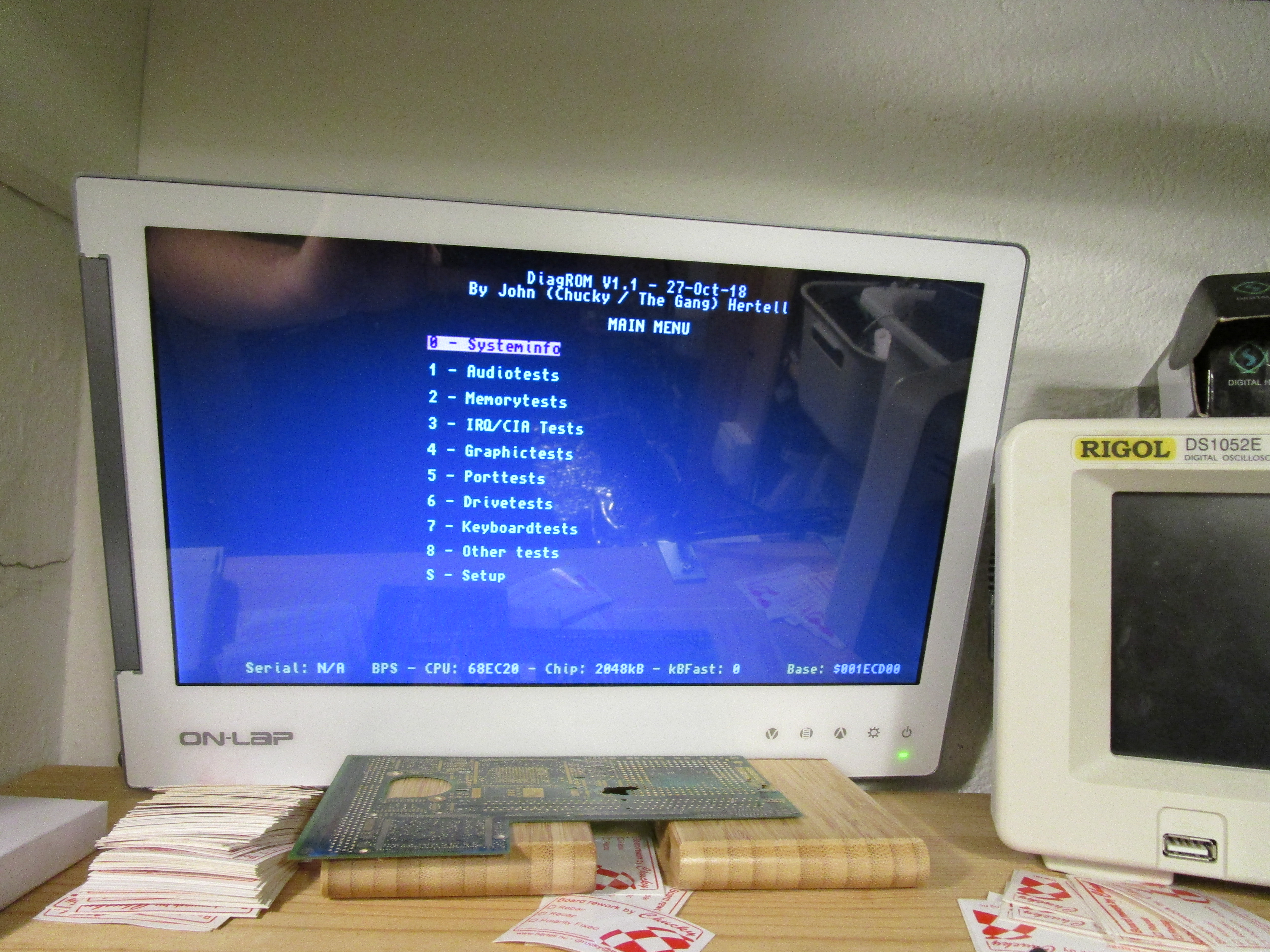
Now your Amiga should output:
BUT! it will crash here. This is a scenario I will try to detect in later versions of DiagROM.
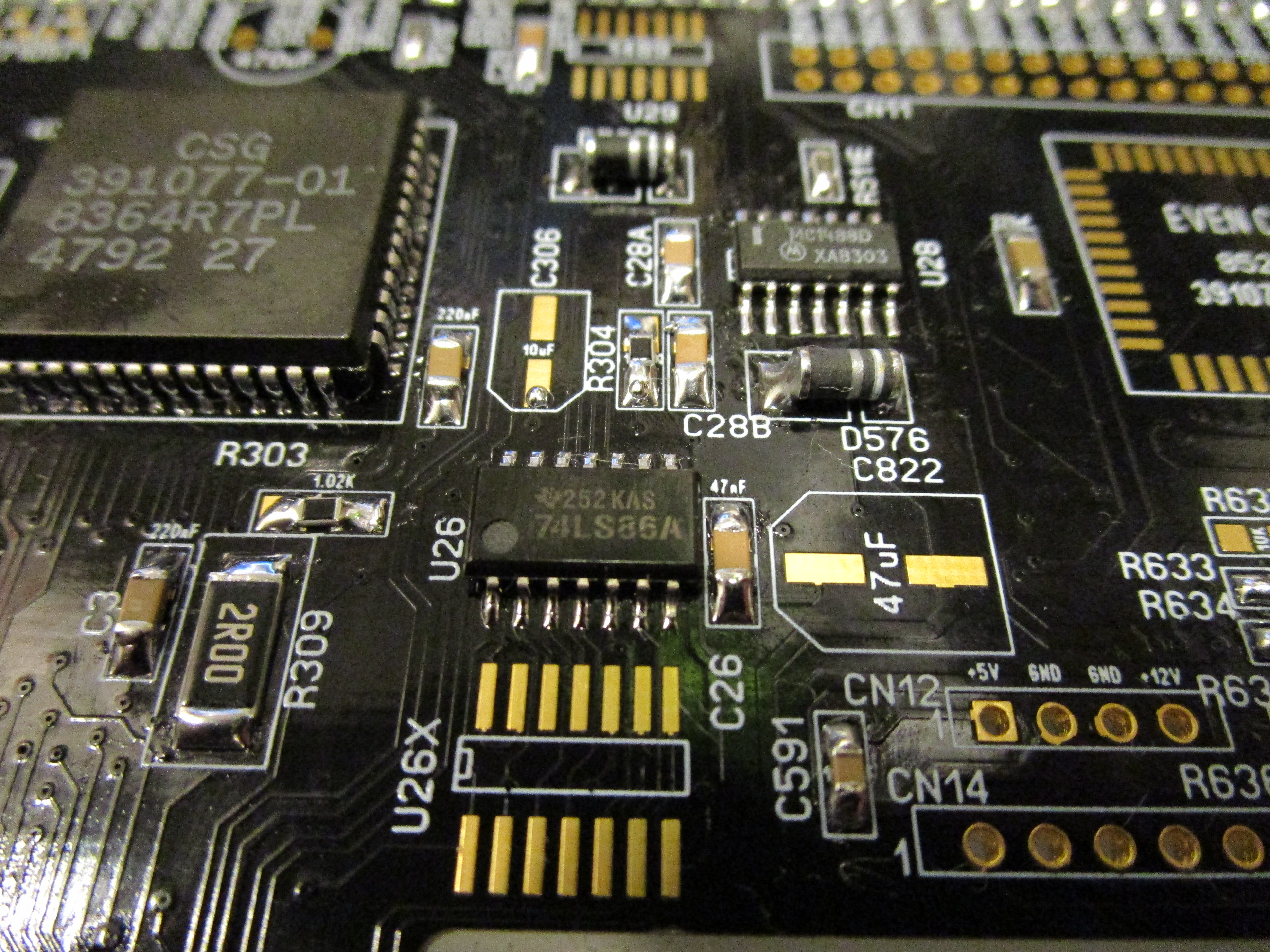
to fix it: Populate U26 with a 74LS86:
And now you should get:
However on the serialport you will get:

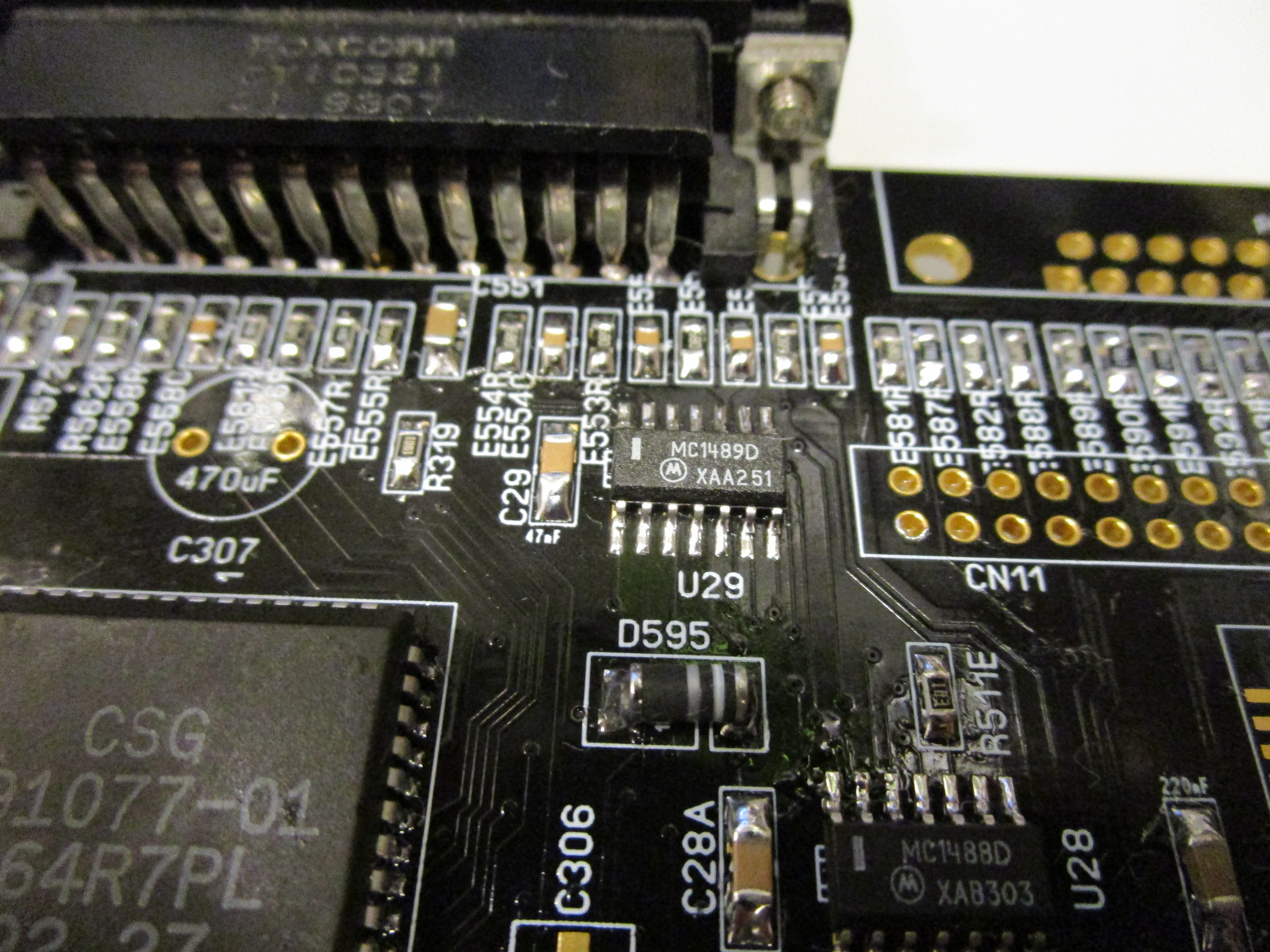
Even if you press any key.. the reason is simple. we need to populate U29 with a 1489 that is handling serial IN:
and Voila:
Now DiagROM got your input and shows the serial console. now you can control DiagROM through your PCs keyboard. (or remote amiga or whatever you have on the serialport)
Machine starts to live!

Hi again, Chucky,
about that zener diode for the ADV101. Would something like an LM385 work there?
Thanks,
Torsten
Found it in the original A1200 schematics. Commodore did use a LM385 here, so I’m all fine. 🙂
Regarding the diodes for RGB output: I tried without them and didn’t get a picture. Only after soldering them in, monitor lit up.
So they ARE necessary to get video output via RGB/VGA.
Is there a scan doubler in this design?
As it sayson the PCB: Nope NO scandoubler
Thanks for your reply. I guess that’s something that could be hacked into the design somewhere. FPGA wrangling time!
Hi Chucky, hoping you can point me in the right direction.
I have just finished installing the memorychips as per your guide one by one checking serial after each one. everything looked as expected. all tests (other than even) are green OK
however, the serial output is stopping after the second Loopbackadaper message and just before the check “Detecting if we have a working raster”
Board is v1.5 and Diagrom is V1.3
Any help is much appreciated.
Cheers
Dave
Sadly no idea.