tl;dr: Files at bottom of this post 🙂
IMPORTANT UPDATE
There have come 2 issues in the files. read bottom of this post!
NOTE!! FILES IN THIS POST ARE OUTDATED! EVEN SOME LINKS!
VISIT www.reamiga.info FOR PROPER INFO!
One slow day (12th of june 2018) being on a hotel doing work for one week I asked on facebook on the “Commodore Amiga” group:
“Reversetime. What pcb do you think I should reverse? Come with ideas. A board often damaged by battery or caps. Preferbly smaller ones. So give me hints of.. “whats next”
I got several ideas. CV64, CD32 etc. then I got the. “Amiga 1200 I have a empty PCB”
So. I asked for a scan of that PCB and got it So that’s why I decided, YES! I will do this. I have a lot of dead 1200s at home and leakage killed alot.
So.. he (Folkert De Gans) scanned it for me. and I started to work on it. this is the reason why it is the Rev 1D.4 and not the latest. that is what we had.
AND. it is also by far the most common board anyway.
I started Sprint Layout and started to do my work.
This is the scanned pictures of the PCB:
BUT! for the mother of god. WHY SPRINT!?
This is a very good and legit question. to design stuff in Sprint is a total nightmare. BUT if you want to make a copy of a PCB. it is fast, really fast and you DO get a gerber in the end. this is why. I totally know that for development it is utter crap. but it lets me get my job done. We can do more PCBs I am happy. I might try to figure out a way to move this data to eagle/kicad or whatever. but until then. I will do more stuff in sprint.
if you want to have a look at the workfile, the demoversion works very well downloadable at:
https://www.electronic-software-shop.com/lng/en/electronic-software/sprint-layout-60.html
Anyway, back to topic
So it started with putting all components at the correct locations (kinda aproximate, not 100% exact position some 10th of millimeters off but good enough.
well.. in sprint you can have the scanned picture as a background:
and then just simply “draw” traces above the scanned picture. and this is why it works so fine for a job like this.
While talking about this on Facebook, another person (Nico Blüthmann) told that he could send me a dead a1200 pcb to help me. and he did.
I decided to remove all components and sand it down to the copper, so silkscreen etc doesn’t confuse me.
So I did:
Now drawing traces is just a matter of time:
Here you can see how I have drawn traces above the scanned picture. Anyway. now it is just the very timeconsuming time to draw everything. and also checking the scans many many MANY times over. did I miss a trace to a via. did I…. I also used http://www.amigapcb.org/ alot by selecting pins of every chip see where it did go. measure on my boards and use the test function in sprint if everything was connected.
and when all traces was done, I “just” had to find what vias should be connected to GND or VCC. and then.. I was done!
BUT. I wanted to do stuff. so what did I want to do?
first of all, the CXA chip for composite is EOL, it also requires some hard to get delaylines (the square weird components close to the powerconnector)
and a friend of mine is doing this nice S-Video/Composite/RGB Adapter: http://electronics.chroma.se/svideo.php
So why not put THAT stuff there instead, RF modulator will be removed. I asked him and got his eagle-workfiles and permission to use his design.
so I did.
I also made traces to power/gnd to the CPU thicker, I made generally all powertraces thicker.
I also added connectors for keyboard like the rev2 PCB of the A1200, and IRQ7 possability, and a jumper so IF you want to mess with the floppy SEL signals you can do this without any strange socketsolutions.
did this. and ordered a testrun of the PCB:

And I started to solder it. it DID start.. but.. my DiagROM only showed flashing backgroundcolors, but nothing on screen.
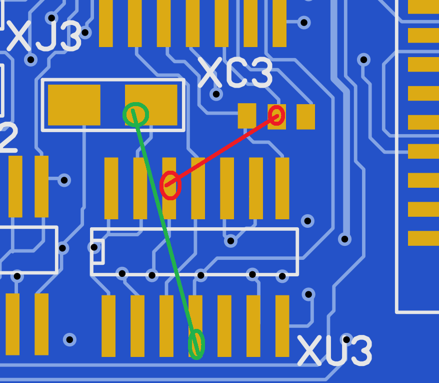
I checked my files against scanned picture and all . everything LOOKS ok. until I suddenly come to think of one thing. Commodore have this throughhole resistor mounted on the pads between ALICE and the FPU Place. and after playing with it. YES.. it now worked.
I also had an issue with I had a stuck FIRE1 pressed on joyport 1 all the time. this was as when I soldered I had some missing components so I moved from the old pcb. it showed that one ceramic cap was shorted doing this. lesson learned: NEVER move passives from the old PCB.
some other minor issues all depending on having the wrong value of components etc at some locations. I HAVE sold some pre-release PCBs. IF you have please click on this link to download an errratafile how to fix this. Updated 2018-08-17: http://www.hertell.nu/webfiles/R1200-Issues.docx
Anyway. I got all working. AND it also does boot a BPPC 60MHz 68060, 330MHz PPC with 128MB ram from a stock light 4.5A Amiga PSU, something my original 1D.4 PCB doesnt do.
so the ReAmiga 1200 is an Amiga 1200 Rev 1D.4 with the following changes:
- Supports Round AND Square powerconnector. (round have 2 incoming +5V wires)
- New reworked Composite logic, with additional S-Video Support
- RF-Modulator removed and replaced with optional VGA Connector that is buffered, Still NO Scnadoubler
- Selectable SEL signals for floppy, you need to cut the traces and solder in a connector to select:
- Optional NMI (IRQ7) Possability
- Resetheader
- A500 Compatible Keyboard connector (actually not tested yet)
- Support for the Ratteswitch with solderoles for required signals so no need of a socket on CIA.
- Extra powerconnectors for +12 and +5V fans. also extra powerconnector close to CPU slot to add power or fans.
- PCMCIA Reset fix so cardreset software is not needed.
- Optional onboard leds where LED and +5V are separated also optional “opt” led, with jumperwire for pcmcia activityled.
I have tested this board for several hours, with Apollo 1260, Blizzard PPC, Blizzard 1230 MK2, MBX 1230. no issues.
BUT this IS a hobby project, I leave no warranty etc.
So BUILDING the shit? well I will do a post later about this when I get the “production” pcbs showed here in this post. as this post would be too long anyway.
Are you screaming for the FILES?
Well sure. as I want stuff to be open I try to open most of my work. this is no exception:
first of all the Amiga 1200 clone. THIS IS NOT TESTED WHATSOEVER. You are on your own! but if you do a pcb and it works and send to me, first person doing that I will send an ReAmiga PCB as exchange:
http://www.hertell.nu/webfiles/A1200-CLONE.zip
Remember the patch I missed:
SOME solutions need a wire between the 2 red marked places. this is for the budgie.
and some needs a 47Ohm resistor between the 2 green slots. or you will not get any picture.
IMPORTANT UPDATE
If you have the Rev 1.0 board. there are 2 faults .
First the BIG one! as I added a possability of having 2 +5V lines via the DIN connector.. I have noticed that when putting in an A500 PSU you will have a short to ground..
As my lab-PSU does not (apparently) have the sheild connection connected.. I never noticed this. but with a proper built adapter or a real psu.. it is connecte. and. yes I am stupid. connected that pin to the din connector..

so using a square connector. cut on the top side of the board as pictured.
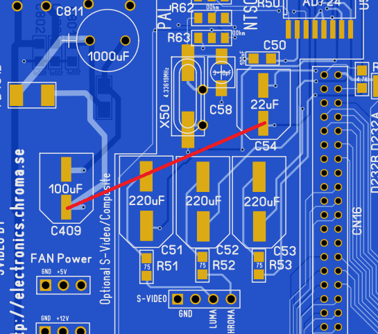
2nd thing. I moved C409 after doiung my R1200 prototype sown so you could use the TH 4.3MHz oscillator.. this made that the videopart will not have +5V, so you need a jumperwire from PLUS from that cap to the plus of C54 and that will work.
Rev 1.2: At composite 0ohm jumpers. R62 NTSC Location was connected to ground and should ACTUALLT be connected to
RGB port (23pin) pin 15. no idea why this fuckup was. Corrected here.. so earlier versions of board
and if you want composite/svideo in NTSC middle pad of R62 shold be connected to RGB Pin 15 instead of a
jumper. PAL Is not affected
IF using a VideoDAC that requires a Zenerdiode, I have now connected the R215 Correctly (was wrong on older
versions not connected to +5V. so you must put a 1K resistor here if that DAC is used. on older rev.
you need to connect the 1K resistor on RIGHT pad of C215 and to +5V (like top pin of D233A)
Added Kickstartswitch functionality,. if you are using 27C800 proms. you can program one bank with one
kickstart and the other bank with another. if R6A (bottom side of board) is set to ENA. the jumper can
select the active bank. High/low with moving a jumper or a switch. (or a pic controller of your choise)
if R6A is set to DIS, the A18 signal is handled as on any Amiga.
to make some kind of PIC for this controlled by joystick fire or mouse left. FIR0 and FIR1 have been equipped
with a TH hole for soldering a wire there.
On older rev. you needed to do a slight solderblob at the pads close to U10 (between it and the FPU location)
this is now a trace. Trace is visible so if you need another “strange” budgie configuration, just cut that
trace and do your stuff.
Rev 1.3 – Skipped as there was a “own” version for the a1k forum not made by me. To avoid confusion
Rev 1.4 – 74LS166 Pin 6 and 8 should be connected to Ground!
Also made changes:
Moved some traces being close to edge and vias, some boardhouses had issues with this.
Added headers close to 0Ohm resistors for audio, so you can skip the 0Ohn resisors and do own “mixing” if wanted.
Moved onboard leds some, so they will not short to a diskdrive. Also added headers for leds if mounted in a Tower.
At powerconnector, added pads for a ferritebead, so if using a round powerconnector the N/C pin can be used for ground. (NOT for use on square connector)
At A500 keyboard connector, exluded the extra HDD signal for the key. if wanted, you add a 1Ohm resistor at back to enable function.
Removed 3 0Ohm resistors at alice. (made them onboard instead)
Well Enough of the old 1200. Lets check the ReAmiga files:
IMPORTANT! THERE IS AN UPDATED GERBER WITH FAULTS ABOVE FIXED!
http://www.hertell.nu/webfiles/ReAmiga1200Rev14.zip
- Analysis Results
- layers : 4
- minimum trace width : 5,9 mil
- minimum trace spacing : 5,14 mil
- minimum drill size : 0,3 mm
- width : 354,9 mm
- height : 182,18 mm
- thickness: 1.6mm
So basically 5/5 Mil tolarance and 0,3mm drillings
for the R1200 there is a BOM file as txt and excel, for the clone you are on your alone.
If you need help where to solder the different components you can use the tool my friend TSB did:
http://www.hertell.nu/locator/locator.php?project=r1200
locator FOR now will be missing the 0Ohm resistor to set Kickstartswitch setting, located bottom side of board under kickstartswitch jumperholes.
Where to get chipsets? well no idea! My reason to do this is to make old dead machines live again. my experience is that most faults on 1200s isn’t the chipset but corroded PCBs and shorted ceramic caps etc. so put in all new passives. move the chipset and logic and connectors and VOILA!
And here is a youtube link of me testing this some hours ago: https://www.youtube.com/watch?v=PlxLs2KYNKw
As the “New Phase5” copyrightstriked me at Youtube he had my channel removed.. you can now instead use: https://youtu.be/jMg3h2Kz1_A
for the video
You CAN buy PCBs from me, contact me for information. atleast the 2 first batches I will give 5 euro per sold PCB to the Swedish children cancer fond:
https://www.barncancerfonden.se/
Hi Chucky,
I want to ask for a build R1200 to buy. Do you ship to Germany?
Andreas
I will ship worldwide. will see about built boards as this takes alot of time to do. so main goal will be empty pcbs
So I order one empty pcb from you. How can I pay?
Andreas
DEAR Chucky,
I am very interested in to get one pcb A1200 board. What does it cost? Do you have also the Chips and other needed stuff?
Would be very happy to get one. Kind regards, QMadx64/Chris
Boardprice will be aprox 60eur each (where 5 will be donated)
chips. I do have dead boards I can use for transplant.
Thanks John.
What a work, what a work. 🙂
Board price?
thanks again
Boardprice will be aprox 60eur each (where 5 will be donated)
nice work sir! It is possible to put your wonderfull board into a A500 case and keyboard? Thanks
Keyboard yes. case no!
Can you use a Amiga 500 keyboard with a Amiga 1200, i thought the Amiga 1200 uses a different connector and keyboard?
Thanks your great work and contribution to the community John.
Regards,
Edu.
Great job, I’m a podcaster, and I’m really interested in buying a board for review.
Regards
I can only sell nonpopulated boards as it is now
Amazing John, keep it rolling!
Regards
Tim
Amazing. I’m also interested by a built unit, if you manage that. I don’t know if you have a mailing list or something where we could keep in touch with your releases/progresses…
For the moment I will not be able to sell complete units..
Absolutely amazing work! I am always eager to see what your next project is!
Thanx. we have to see.. 😉
Fantastic work here. Really impressive, especially the time line! Did you really conceive of the idea in June and have a working reimplemented board in August?
Amazing Chucky!
Rock on,
Keith
Thanx. well with sprint it is fast
Wow! I would be interested in buying one!
I am currently out of PCBs will order more today
Sure, please put me on the list and let me know the payment details.
Hi John, thanks you! id like to buy the pcb and the needed proprietary chips, can you send me and email with some price and info?
I can sell PCBs but no chips etc.
any plans to do a modernized one? like add in ide buffering and an rtc onboard or some other stuff that should probably have been there in the first place, perhaps an itx one with built in usb mouse/keyboard ports?
Well we have to see. maybe for the future in a year or so. for the moment just small changes.
IDE buffereing is something I am thinkning of. but to do anything larger I really REALLY need to move the data to some other software than sprint
Hi Chucky,
Last week I wrote you, that I want to buy one pcb. But how Can I make an order and pay?
Great job, and I hopeyou will do more loke A3640 or R1200.:-)
Andreas
I have ordered more PCBs and are waiting of that batch to come
please put me on the list and let me know the payment details.
Hello Chucky,
I was checking out your latest pcb layout of the Amiga 1200 ver. 1.1 using Sprint layout and wonder if the added ‘power-connector’ – close to the expansion port – is connected properly? The +5v seem to lack connection to any power source or power plane.
Am I wrong?
Marko
Sorry, I checked it again and it seems to be connected 😉
My bad 😀
yes. it is via the filters.. 🙂
Hi John,
How can I order 2 x 1200 PCBs and is it possible to pay with PayPal?
Best regards
Kenneth
Sent you a mail
Wow… this is amazing.
Would love to have a new A1200 PCB… Sadly though I would need to get one that was ready to go, since my fingers tremble way to much for me to be able to solder capacitors etc to a PCB, much less chips…
I have 2 A1200 computers, both are still running but I am not able to recap them due to my condition. So if I were able to buy a PCB that was ready for use, then I could swap out the PCB in one of my A1200 computers.
One of my A1200 computers seem unable to boot from HxC and Gotek, but boots fine from floppy, while the other one boots just fine from either HxC or Gotek drives.
Do you have any donor A1200 bords left, do you have any PCB’s in stock and do you know if the chips on the donor A1200 boards will boot from HxC and Gotek drives?
I have no donorboards to sell or built boards.. just sell the empty PCBs..
Ok I understand. I wish I had the skill to transfer the parts from My escom amiga 1200 board 🙂
Hi there, impressive work, I would like to get a complete unit, when available, if you please let me know in the future when you have it for sale, thanks and keep this great work.
complete systems will more or less not really happen. just replacements.
Hi! I would be interested in purchasing a board, how would I order one? Would also be interested in chipset, optionally also the needed components as a “kit” though that’s not important as I can always find those elsewhere.. 🙂
Sent you a mail
Hi, I would like to buy one PCB too! This looks awesome!
Shipping would be to Germany.
Sent you a mail
Hi Chucky,
Can I order one PCB for me? How could I pay? Could it be a bank transfer in EUR or USD?
BR
Pekdar
Sent you a mail
John – love your work.
Mate I’d really like one of these Retro 1200 boards please.
Can you get in touch with me if you have some available?
I will send you a mail!
I have a desoldered clean PCB. This is a CPU card from CS MK 1. If I send you, you will be able to do reverse engineering it. ?
If anyone could buy a reamiga 1200 pcb and get the parts and make it a fullly functional reamiga 1200 machine and lives in the EU then I would be interesser If the price was fair.
Great work. But can i ask do u have any plans to make a board for A500+??
thanx. A500+ no.. but A3000
You’re really working on a A3000 Board ? Great !
Do you have more information about your A3000 project ?
well that is for later
I’m looking at doing an A500+ board. Got the board mostly stripped down and will start work on the reverse engineering soon.
Fine! this is what I hope to start people doing spare pcbs
Hi, I received my board recently but i assume that it’a a PAL system? Would anyone know what modifications need to be done to make it an NTSC system?
put in a NTSC Oscillator instead of the PAL set denise jumper (lowest of 3 0ohm resistors at the composite area) done
Thanks mr Chucky!
THIS IS A VERY HARD THING YOU ARE DOING IT MUST HAVE TAKEN U WEEKS ,, I UNDERSTAND YOU TRANSFER CHIPS FROM OLD 1200 TO NEW BLANK PCB …IS THAT CORRECT ?.
GOOD JOB U HAVE DONE
Usually I do that yes
Hi Chucky
Just wondering if I sent a working A1200, if you would transfer the parts (for a price of course)?
Cheers
Brian
I had done this now for 3 machines. but thinking of it.. and. decided to not to. if there are any motherboard issue I will do it.. working.. no.. not anymore. it just feels wrong. sorry
No problem, I really respect that answer.
I’ll keep using the existing board until it’s not working.
Is Budgie Patch required in rev rev 1.1?
no wirepatches no. but the 74F32 will still be needed
I have soldered rev1.1 and I do not have a picture, just a black screen
look for bridges especially on the budgie and cpu
Hi Chucky,
thanks for this marvellous piece of reverse engineering. 🙂
After towerizing my original A 1200, I still have the empty case and lots of goodies, so I thought of building the ReAmiga from the ground up.
Since I don’t have a dead board, I sourced all necessary chips and components as NOS.
However, the Chip RAM is a problem. Do you think that these new ones will fit: V53C16258HK35.
They are sold as SOJ40 package, do have the same pinout as the original RAM chips and seem to be electrically identical. They do, however, have much faster timings.
Will this be a problem or will they just be “slowed down” to fit?
Thanks in advance,
Torsten
if they are pincompatible they should fit.
speed is not an issue. as the speed is just what they can handle. they are not clocked in that speed.
Hi Chucky,
great work what you have done !!
please can you tell me more about the filter ? So you have an spare part number of it ?
Not listed in BOM. Board version is 1.2
I had some filters at home that I used. not really checked them up sorry
Hi
Amazing project
I would like to order a board if you have any left 🙂
Thanks
Stefan
thanx
for the moment I have no boards available. will do a run later but not right now
I’m interested in a board! Do you still have any available?
I might do a run later. but have none now
Hi Chucky, what about the new phase 5 project?
Why a company that seems dead for ages is still being a pain in the nek?
Have you a last revision board in house?
Kind regards
he is just a problem with mental issues.
I have no boards that I can sell for the moment
Hi Chucky, may be, one day, some misterious forces can put your job on a lot of anonimous torrents server so people can enjoy those things …. but it is not your fault…
the the sources code of the workbench :-)))
Kind regards
This looks to be amazing work.
Do you allow people to have their own PCB’s made and sell them?
Would you want a commission on that?
Also, are you planning on doing another board? Maybe an Amiga 600 perhaps?
Thanks for your hard work!
it is ok to do own boards and sell. but then you take the support 🙂 the boards I sell is watermarked so I can see if it came from me.
but go ahead!.. some send me money, some not.. it is fine by me.. that’s why I do this open. 🙂
Hi Chucky – any chance you still have boards available?
Well yes I got boards. dump me a mail at: johnhertell.nu
Hi!!!
I’m interesting in two PCBs. It’s possible?????
for the moment I have no stock
ERRATA: I think I found a fault in the latest ReAmiga1200Rev14-zip file.
There’s a short in the design bottom side, at the bottom edge under the footprint for the math coprocessor; a capacitor named ‘COD’ with following value: 47nF is shorted with a trace passing the capacitor.
The capacitor pad should be moved upwards.
Interesting. so it seems. weird. need to check it out.. thanx for pointing that out
Hello
First of all, a big thank you for the remarkable work you have done.
I am about to finish the soldering of all the components and I have a few questions:
at the location of some passive component, there is no value. should we leave blank or should we put something else
on the logic components U26X XU2 and XU3, no reference, must we also put nothing or put 74f02 for xu3, 74f74 for xu2 and 74ls86 for u26x
finally, the revision that I have is the 1D4, must we put the resistance of 470 ohm between xc3 and xu3 if XU3 and XU2 are blank
if XU2 and XU3 are populated should we still put the resistance?
Thanks again for this wonderful work
Put components AS on the locator and it will work.. nothing more or less..
that reistor on pads that is on 1d4 issue is solved on the pcb already.
so as locator..
(if your reamiga is earlier than 1.4 you need the 3 0ohm resistors right of alice..)
hi chucky
I have a broken A1200 rev 1.4 motherboard;
Power on the light is on but the black screen. you could possibly repair it for a price of course.
Best regards
Sorry atthe moment I am doing no repairs
Tank you for the fast reply.
Best regards
Is there a 1.5 revision of this board and If there is where might I find one ? Thanks 🙂
there is.. I have someleft for sale. black and blue
I’m trying to build one based on your rev 1.5 board. Finding a Budgie rev 0 (391425-01) is almost impossible. Can i use a rev 1 (391425-02) instead. Do i have to make changes while using a rev 1
that version works just fine as it is!
Currently I’m working on a project for recreating A600, I have succesfully recreated the board and it boots succesfully if You would like I can send come pictures, I wanted to ask if I can use “ReAmiga” naming on the final board.
Hi, I would like to buy a black pcb (v1.5 I assume) from you.
How to proceed?
Regards Roger
right now out of pcbs..
Hello
Just a question
I want to use a classic Kickstart 3.1 rom with 2 Chip .
Where must i put the kickstart jumper swtich: on Low or on High
Best regards
Hello Just a question
I want to use a classic Kickstart 3.1 rom with 2 Chip .
Where must i put the kickstart jumper swtich: on Low or on High
Best regards
Hello. there is a small bug that someone detected on the version 1D4 card at the level of the C0D capacitor (contact with a track). Does this bug prevent the card from starting up and if so, must we do something to correct this bug and how ?. wonderful reverse engineering work
it is in the erratapost. no it will work “fine” without it fixed. howeve you should fix. info in the erratapost
Every PCB fab want to know the layer sequence
L1(Top layer)
Select
L2(Inner layer1)
Select
L3(Inner layer2)
Select
L4(Bottom layer)
can you let me know what these should be?
top layer: R1200-Rev15_copper_top.gtl
l2: R1200-Rev15_copper_inner1.gl2
l3: R1200-Rev15_copper_inner2.gl3
bottom: R1200-Rev15_copper_bottom.gbl
I just purchased a red board on ebay. Are other colours possible?
I never sold any red. but the gerbers is out so anyone can produce any color they want to
Where is the link to buy your PCBs?
http://www.reamiga.info
How can I order?
I would like to buy a board
gerbers on http://www.reamiga.info or mail me at chuckythegang.nu
Hi,
I’ve just build one board but when I power it on I get a black screen (signal video is alive).
No serial output (DIAGROM on board) and both _RST and _KB_RST LED always lit up.
Any clue ?
Many thanks in advance
Common thing when that happens is that the keyboard MPU does not get a 3MHz clock
Hi Chucky, where should the TC54VN4302ECB713 go on an re-amiga 1200 Rev 1.5?
U49. if you look “up” some.. 🙂
Thanks for yoyr reply!
Found it allright! 🙂
But I may have made a mistake or 2. And cannot find the problem. I get “garbadge” at the serial port and I am left with a red/green blinking screen and eventually green/dark green screen (with additional horizontal stripes). I have been probing and testing for days now and cannot find anything wrong. I have even exchanged the custom chips with my working a 1200. They work fine there. But when transferred back issues still the same.
I have gone down the rabbit hole with testing and swapping the components arround that I now have borked my bord.
I also noticed that diagrom is putting out the same garbage on my working board, so by now everything is a suspect.
Anyway, I would like to order 2 boards from you black and white. Is that possible?
I am such a dork. I had a closer look at my null modem cable. Appearantly my FTDI adapters do not work. Had to buy a new nullmodem. Diagrom was showing garbage even on a known working machine. The RAM issue is still persisent, but I believe I found that isssue too. I have the wrong memory I think. I am now investigating that.
Hi John,
What’s the name and model of your flatbed scanner that you used to scan the PCB? I tried to scan a PCB with my scanner, but the depth of field is not good. Thanks in advance.