Time to get some code running on this.
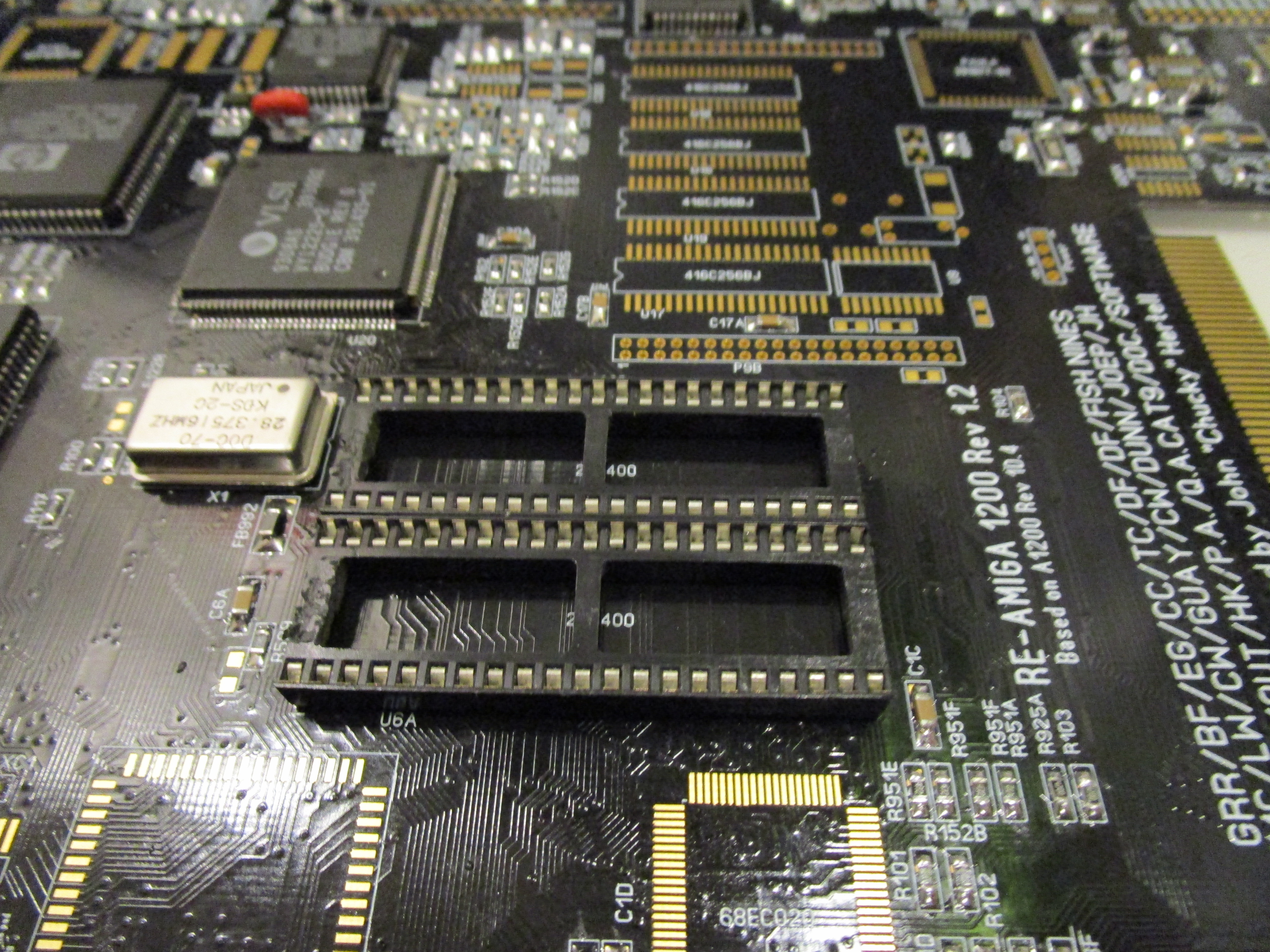
Time to get this board to a state that I call “minimum startup” it means this is the minimum population of components needed to get Diagrom to start.
First add the Keyboard MPU:
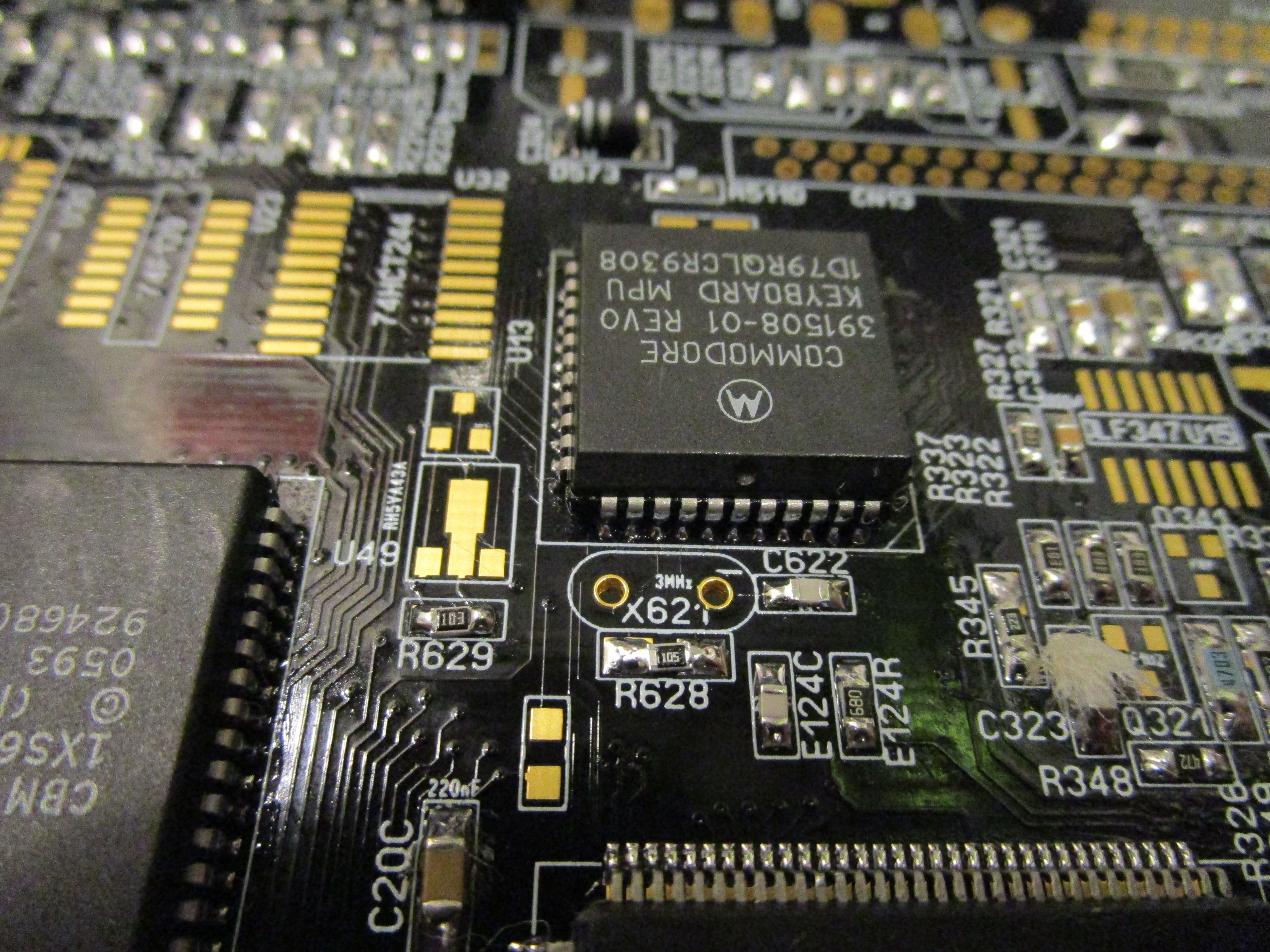
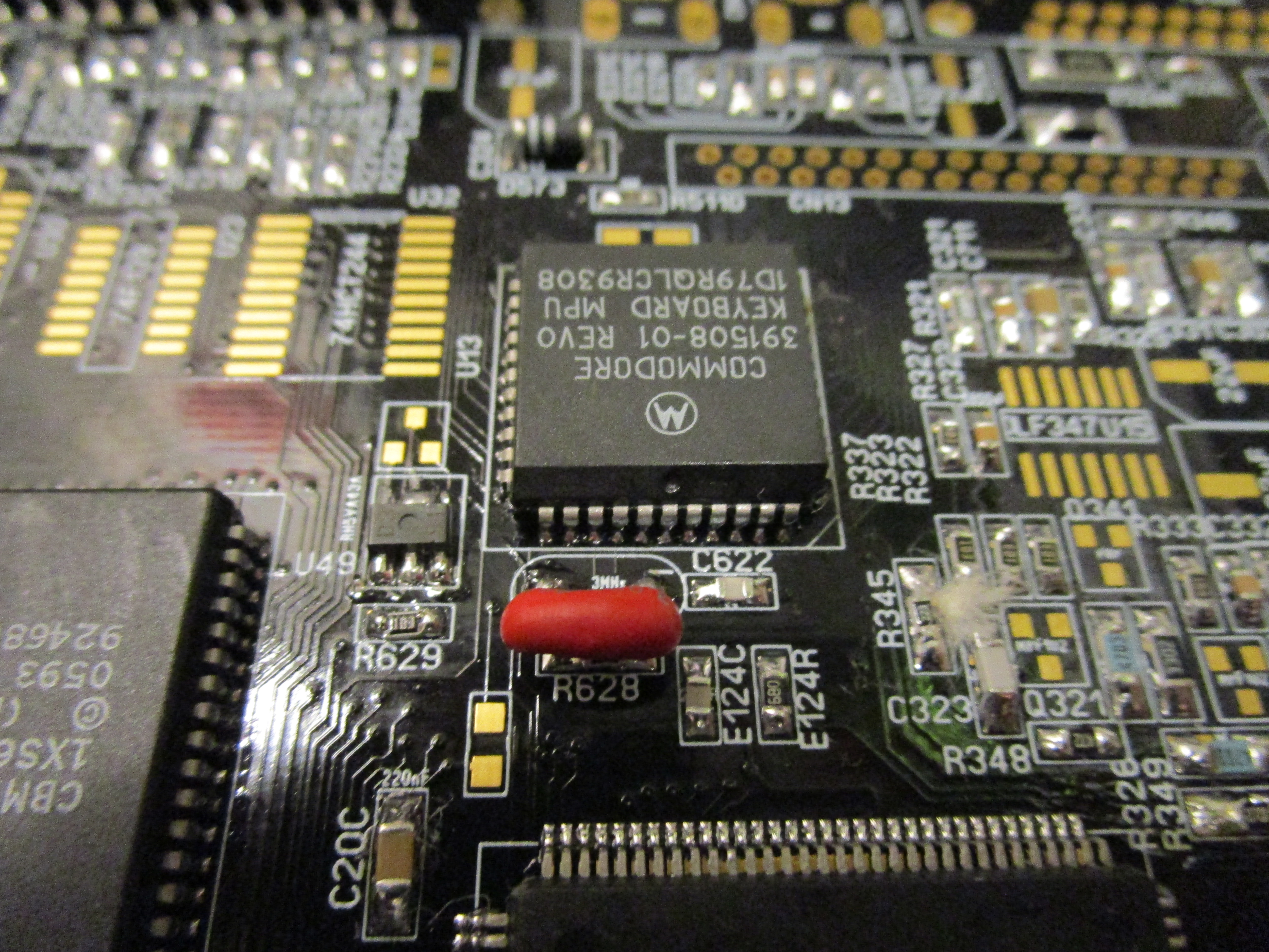
And then the 3Mhz resonator/oscillator (NO it is not a cap that some believes it is)
and the Low voltage detector. both are extremly important as the machine will not start without those.
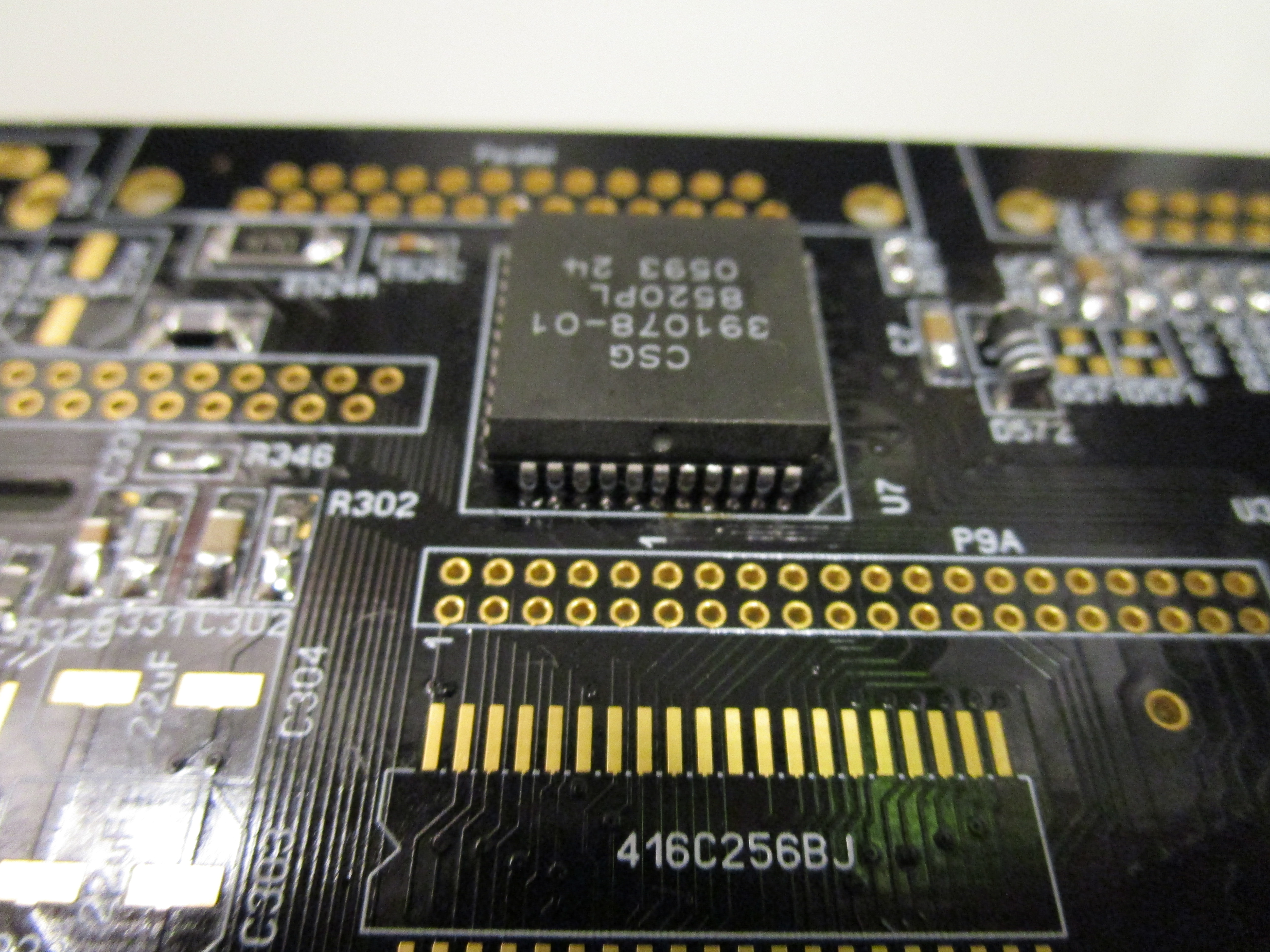
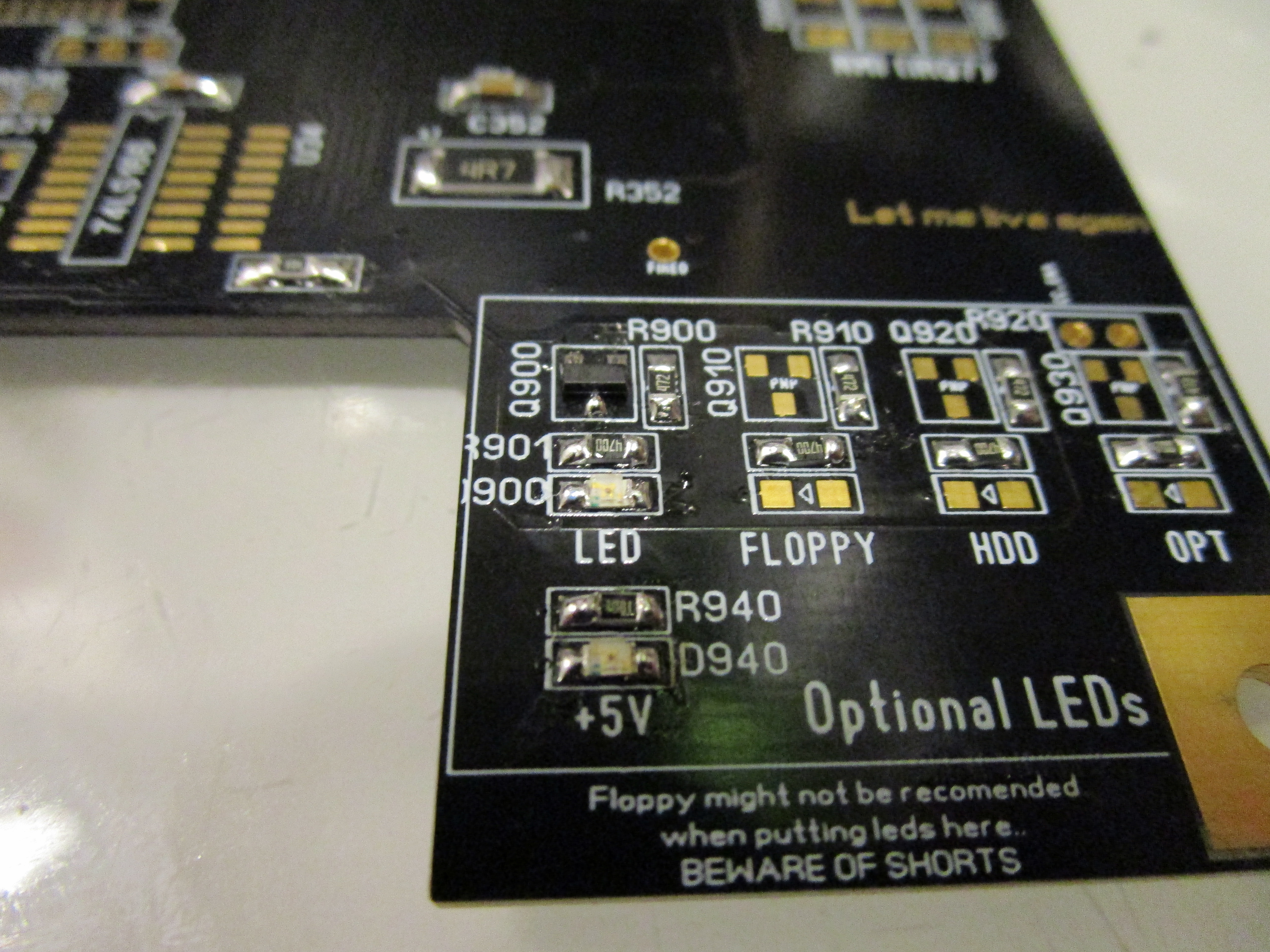
as our goal is to get the “LED” flashing. ODD CIA is needed. TECHNICALLY this is not needed to run the code. but to make it visible.
So lets add it:
Now to get ROM to be enabled. we need the GAL:
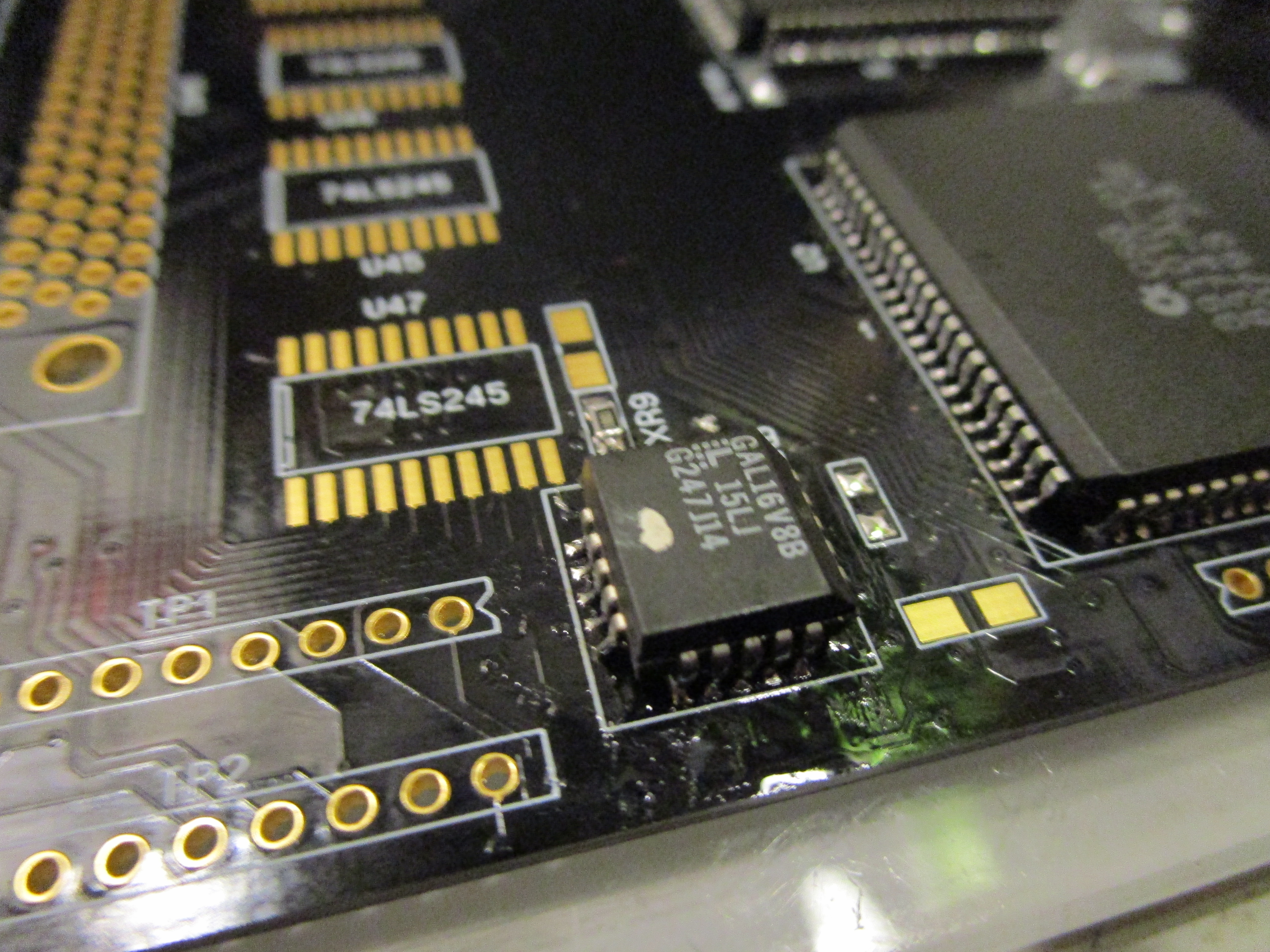
IF you are moving components from a Rev 2B PCB you CANNOT use the GAL from that board. it is for XU1, this is XU9. in the ReAmiga archive you will find the JED file for XU9. you need to have that programmed. or machine will NOT start.
And add sockets for the kickstart EPROM:
And time to add the led and the PNP Transistor needed:
Put 2 roms With DiagROM into the sockets (any version will do. but I do this post using DiagROM V1.1)
If you now put in a CPU card, the machine will start and you will see the LED flashing quickly:
EDIT: I have found that it might be needed to also add the 74HCT244 at U32 at this point to get it to work better.
So do it as a habit to install it at this point aswell.
if you have no fastmem on the board you will get a slower flash similiar to a guru. either way it should flash. if it doesn’t check your solderings. (most common issue is a bridge somewhere usually the budgie)
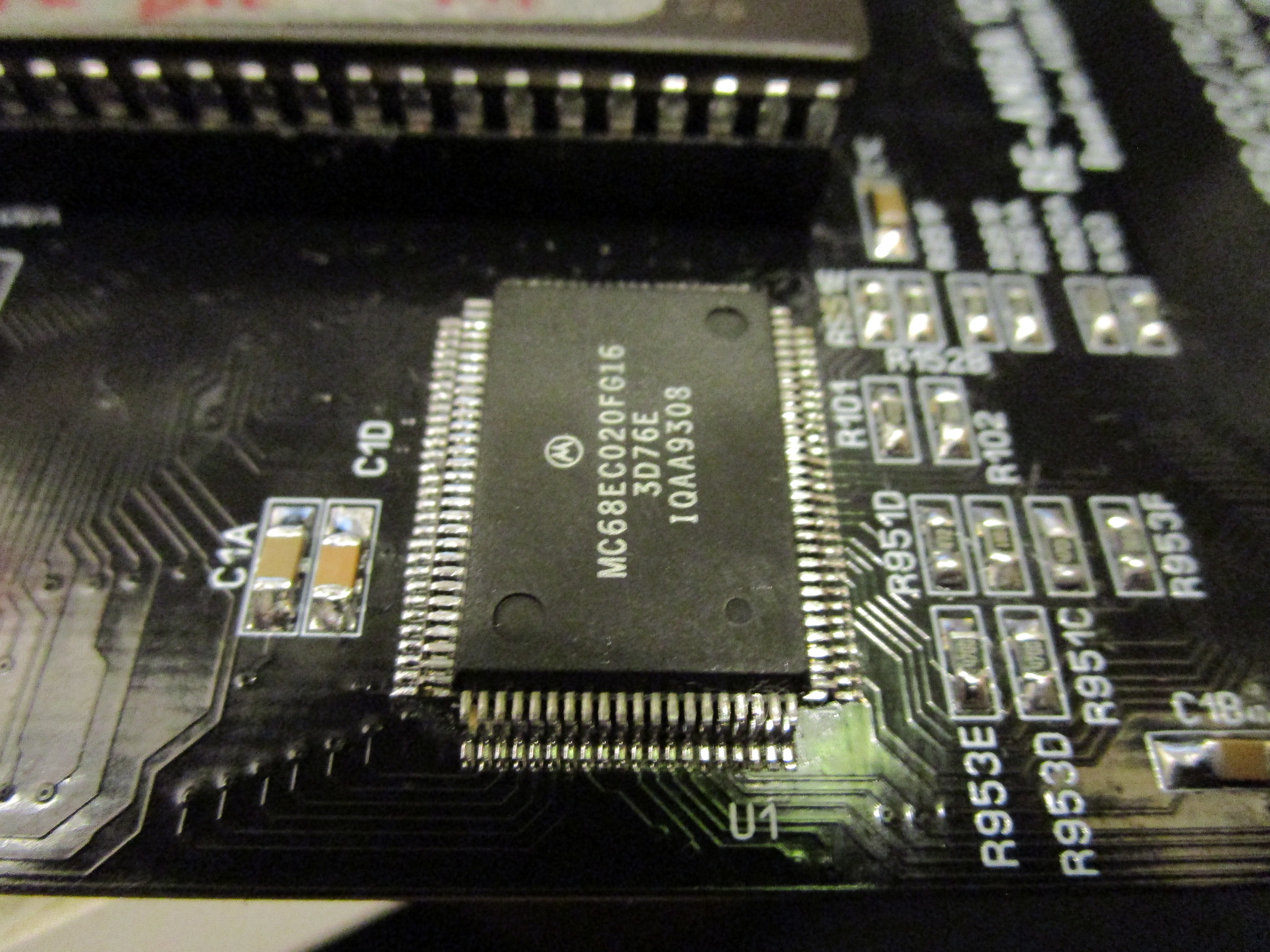
NOW add the CPU. the reason we did test without cpu is that the cpu is the hardest solder in this project. now with flashing led. we know that the minimal setup is working. if it doesn’t work with cpu. we can concentrate on that ut must be a issue with cpu or (most likely) a bad solder on the cpu.
Now turn on the machine. You will get a “guru” similiar LED flash. this as DiagROM will detect the paula as defective/missing. so it will skip serial output and chipmem detection will be done extremly fast. Putting the machine into “No mem found” mode, flashing the LED.
Now we will need a serial output to help us in the future. So to do that, lets add the PAULA and the Serial DSub. (25Pin Male):

This will however not be enough, we need to put in the 1488 Chip at U28 to be able to atleast SEND data to the serialport:
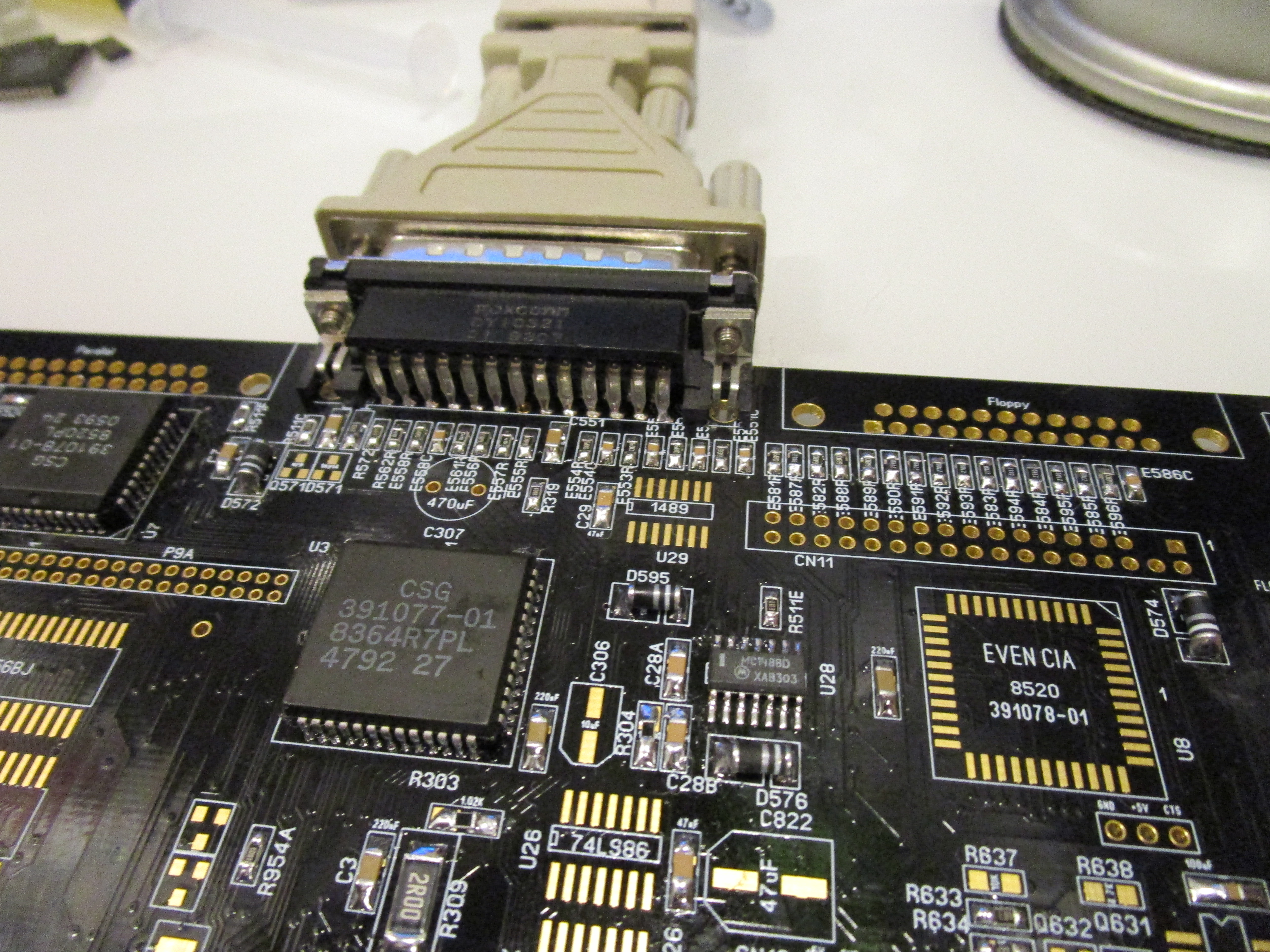
Now you need to connect a Null-Modem (DiagRom doesn’t use handshaking so TXT, RXD and GND is only really needed pins) to either another Amiga using NComm or so set to 9600BPS 8N1. or as I do, to my Windows PC using PuTTY. (via a USB Serialport):
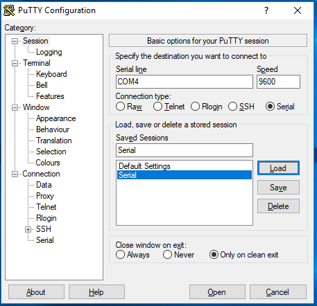
COM4 is my USB Adapter. set to 9600 BPS (and connectiontype Serial). and press Open.
a black screen will popup. and when you turn on your Amiga you should get:
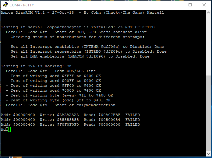
(and a memtest (that will fail) will be scrolling down the screen)
Your machine now starts diagrom. this is the point we will get things to start smoothly in next part.
Hello, i need a pice of advice.
Everthing works fine for me up until i get the serial output. It is just diagonally writes jibberish in putty. If i attach my indivision and look at the output i can se the flashing green/red status image from Diagrom and the Power Led is flashing quickly during the memory test and when it finishes it blinks slowly.
Do i have a problem with the paula chip?
Paula is a very tough girl. it is hard to break it.
my guess is a short somewhere. around bit 24-31 I guess, at memory, bridgette or so.
Hi Chucky,
when trying with CPU card (or with the 68020 soldered in, for that matter), if I power on, the LED flashes once and then stays lit with full brightness.
I’m getting no output on the serial. I’ve already checked all the solder joints several times, but can’t seem to find any bad ones. All of the chips get warm to the touch quickly after powering on. Alice and the CPU get what I’d call moderately hot. What could I be missing?
Can this be related to XU9 so the ROM does not start? I programmed it with a TL866 and remember that you said somewhere that this could cause problems.
Thank you and best,
Torsten
Hi again,
I solved my problem (and am a bit embarrassed).
At first I tried to narrow down the issue by
– replacing the reset generator -> no change
– redoing several solder joints -> no change
– trying without XU9 -> LED stays off
– trying with an empty 16V8 in XU9 -> LED stays off
Then I turned the board over and almost immediately spotted the cause of the Amiga not starting: While soldering in the Kickstart sockets, I completely forgot one leg right in the middle of U6A. D’Oh!!
Redid some of the other legs while at it and – voilá – seconds later hat a serial output of Diag ROM on screen that fails at RAM check as it should.
Okay, after this adventure, today I’ll only clean up and leave the RAM for tomorrow… 😉
Best,
Torsten
Hmm, and now just another problem popped up.
During startup test, DiagROM outputs:
Testing if OVL is working: OK
– Parallel Code $fe – Test UDS/LDS line
– Test of writing word $FFFF to $400 OK
– Test of writing word $00FF to $400 FAILED
– Test of writing word $FF00 to $400 FAILED
– Test of writing word $0000 to $400 FAILED
– Test of writing byte (even) $ff to $400 OK
– Test of writing byte (odd) $ff to $401 OK
– Parallel Code $fd – Start of chipmemdetection
Are the three failing word operations on the CPU sign of a bridge or bad solder on the CPU or do I have to look somewhere else?
Thanks,
Torsten
Okay, Problem solved. After soldering in all chipmem and U26, the $400 write tests check out as OK.
PS: Also, the DiagROM menu works through serial and extended chipmem test succeeds.:-)
I can’t get the LED diode to blink. Sometimes it shine continous or shortly blink and dies. I’ve checked and replaced the 3.00 MHz resonator and ODD CIA chip but still no blinking or even get the LED to shine. Sometimes it do shine even when I dissconnected the masterclock oscillator ( yes I socket it to test it ). The CPU gets moderatly warm and the Alice chip too, but that’s all. Any ideas? Can it be faulty caps somewhere?
Problem solved.
What solved your problem?
Hi Chucky,
I’m stuck at the serial test after adding Paula on a ReAmiga Rev 1.4.
I get no serial output while the led is flashing slowly and after a minute it flashes a bit faster.
I socketed Paula and without it I get the fast flashing with the slow guru like flashing afterwards.
Could you please give me a hint where to look.
Thanks,
Jan
late answer.. are you sure your socket is proper soldered.. with socketd ics usually the soldering is the issue. inspect under microscope
Hi Chucky,
I have all the components soldered to the board. When power on I get Power LED lighting up but not blinking. Sometimes _ROMEN LED stays on, sometimes goes off. Usually TXD LED lights up and remains lit. I can see nothing on serial port appearing though. _ODD_CIA and _EVEN_CIA LEDs don’t light up. CIA at U7 gets reasonably hot, all other components are at fair temperature.
I’ve checked soldering for proper connections and bridges and so far found no shorts or connection issues. With a logic probe I can see quite a bit of activity after power on all components.
Any ideas?
Thanks a lot,
Marton
all the components? you didn’t stop and troubleshoot when it did not follow the guide? well it can be a bridge anywehere or failing component.
this is why all is done in steps so it is more easy to find the issue
Hi, when using the diagroms, do you need input from a mouse or keyboard or can you input just over the putty/serial ? i ask as i have a PCB that i am checking current status of i can see the output on the terminal but do not seen to send input.
Many thanks, P.
you can input from serialport
Hello,
i can not find the JED-File on the ReAmiga-Website. Could you may add a link?
thanks!
it is in the gerber archive
Hello John et.al., I managed to get to where the diagnostic ROMs are installed on part 2 without a cpu card. Is it normal that the diode D900, that is supposed to blink with CPU card, is permanently on? See video here: https://www.icloud.com/sharedalbum/#B1a5fEtEvszVYxX;AC106EAD-1E03-4E84-B833-8D4910D884B1 Also, is there a way to measure the horizontal / vertical sync rate on the optional VGA part with an oscilloscope? I searched the Internet but could not find anything resembling a tutorial etc. Last but not least I find ALICE having a higher operating temperature (~ 47 degree Celsius) than most of the other larger chips (between 34 and 38 degree Celsius). Is this expected?
Sorry for late response: the LED should blink with DiagROM yes. as it does different tests.. (blinking to show there are activity)
measure h and v sync. most oscilloscopes does it automatically. mine shows in upper right corner.
alice and paula is somewhat hotter of all of the chipsets
Hi,
i currently have the same situation. Test and Power-LED are always on. Have solved this? If so,,how? 🙂
thanks
Peter
Hi John, would a Rev1 MPU work on a Rev1.5 mainboard?
yes
Hi John , looking for advise on the keyboard mpu .
if i buy one from china , do i need to program it ?
if so is there code somewhere to use ?
thanks for all the good work
Mike
https://www.amigawiki.org/doku.php?id=de:parts:keyboard_mpu
Hi,
I’m at the point where the LED should flash with the processor card in place and it does not light at all. What could possibly cause this?
Details:
– chipset rescued from old rev 2B board
– new XU9 from tbtorro@amibay
– DiagROM v1.3
– CPU card used is a brand new ACA1234-50
– low voltage detector and oscillators from old board
– U11, U32, U34 in place, all new parts
– up to this point everything went OK, VGA sync with monitor etc.
– I have checked, rechecked, and checked again for bad solder joints, bridges etc.
Does no LED at all mean that DiagROM is not starting at all?
if 5V led is not on. then you have no power at all…
and if LED is not blinknng /go on. it seems that no code is running. (OR something else. then to verify if code is running is to check datapins with oscilloscope)
how does the RST leds behave?
5V LED does come on normally but the D900 LED does not. I do not have the _RST or _KB_RST leds in place yet. Will solder those in and check.
On power on, _RST goes ON and OFF once, _KB_RST flashes ON twice and then stays OFF.
they should be “synced” if U32 is correct..
but staying off is a good sign. well.. it can be a bad chipset. bad GAL or solderingissue. (or passive wrong…)
hard to say more.
90% of times people had issues here it is usually a solderissue
Checked joints again and resoldered some. Now, when the _RST led goes off, the test LED goes on and stays on continuously so I guess DiagROM still does not start.
ACTUALLY that can be fine. as I write that led should atleast go bright.
adding paula will most likly make it flash
Added Paula, serial DB25 and 1488 along with a couple of diagnostic LEDs.
_ROMEN behaves exactly like _RST, there is no activity at all on _ODD_CIA and TXD led is ON all the time but not with full brightness, kind of dim. No change on test LED, it goes on and stays on when _RST goes OFF. Tested serial connection too and there is no activity.
This is fixed now and DiagROM boots fine. Just for reference, I went through the chipset solder joints once again with a microscope and redid a couple of slightly shady looking ones and that’s it. Listen to Chucky, the most likely problem you’ll have is YOUR SOLDER JOINTS. 😀
hehe that it my mantra 🙂