ok this part is more about the extras etc.
First we have some weird A1200 “extras”. as you might have noticed I missed one transistor and one diode at the parallelport:
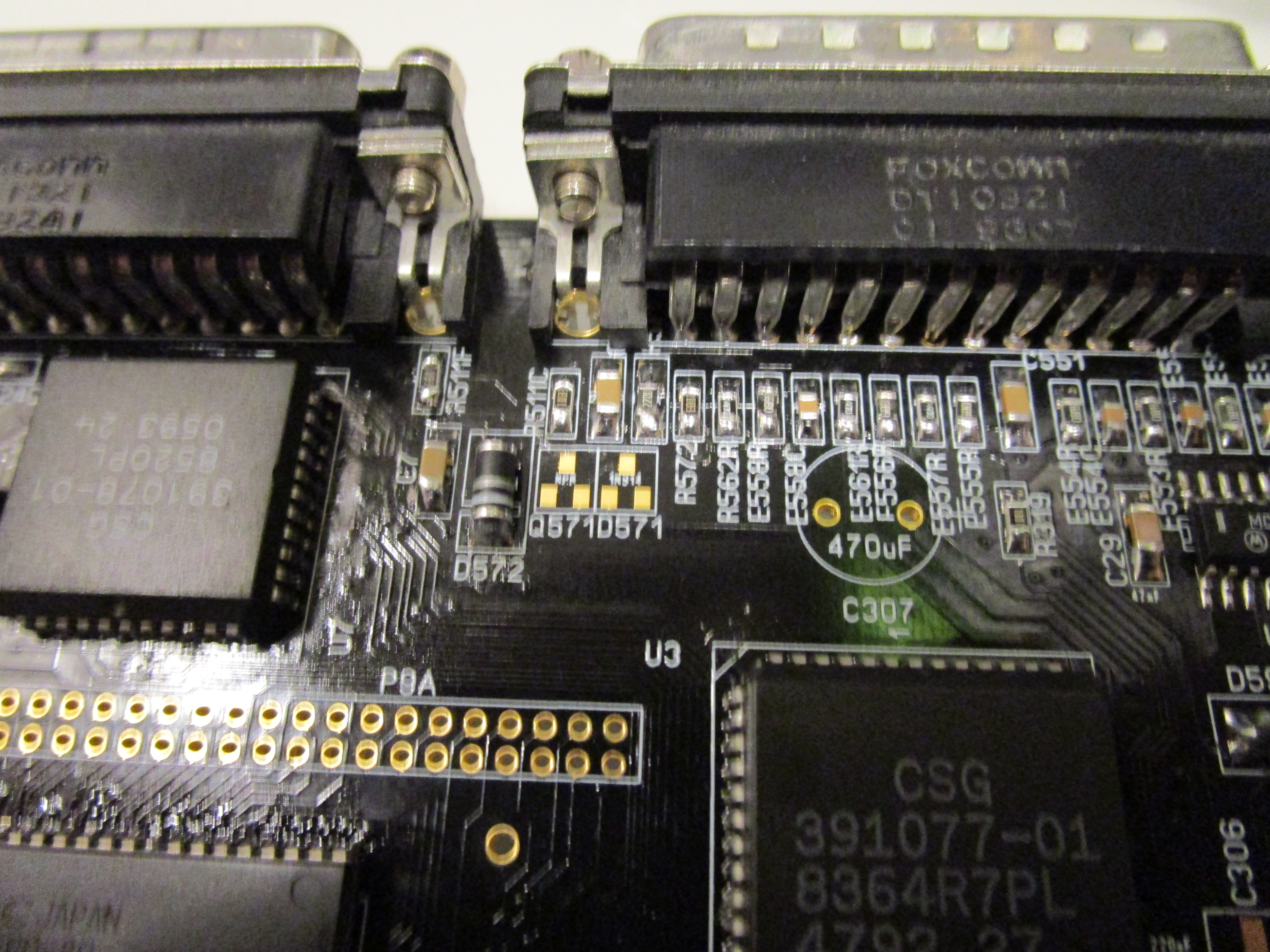
Looking at schematics
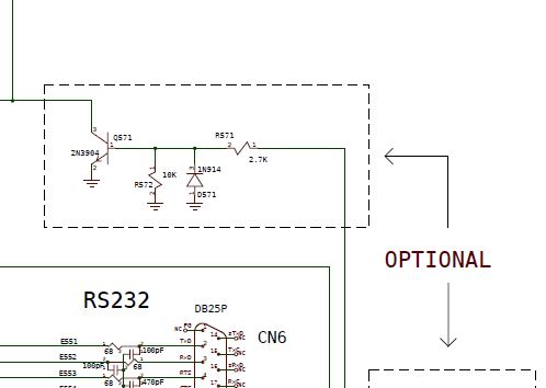
this is “optional” seems to be connected to the audio in. I might remove this in the future. but for this card. I will populate it:
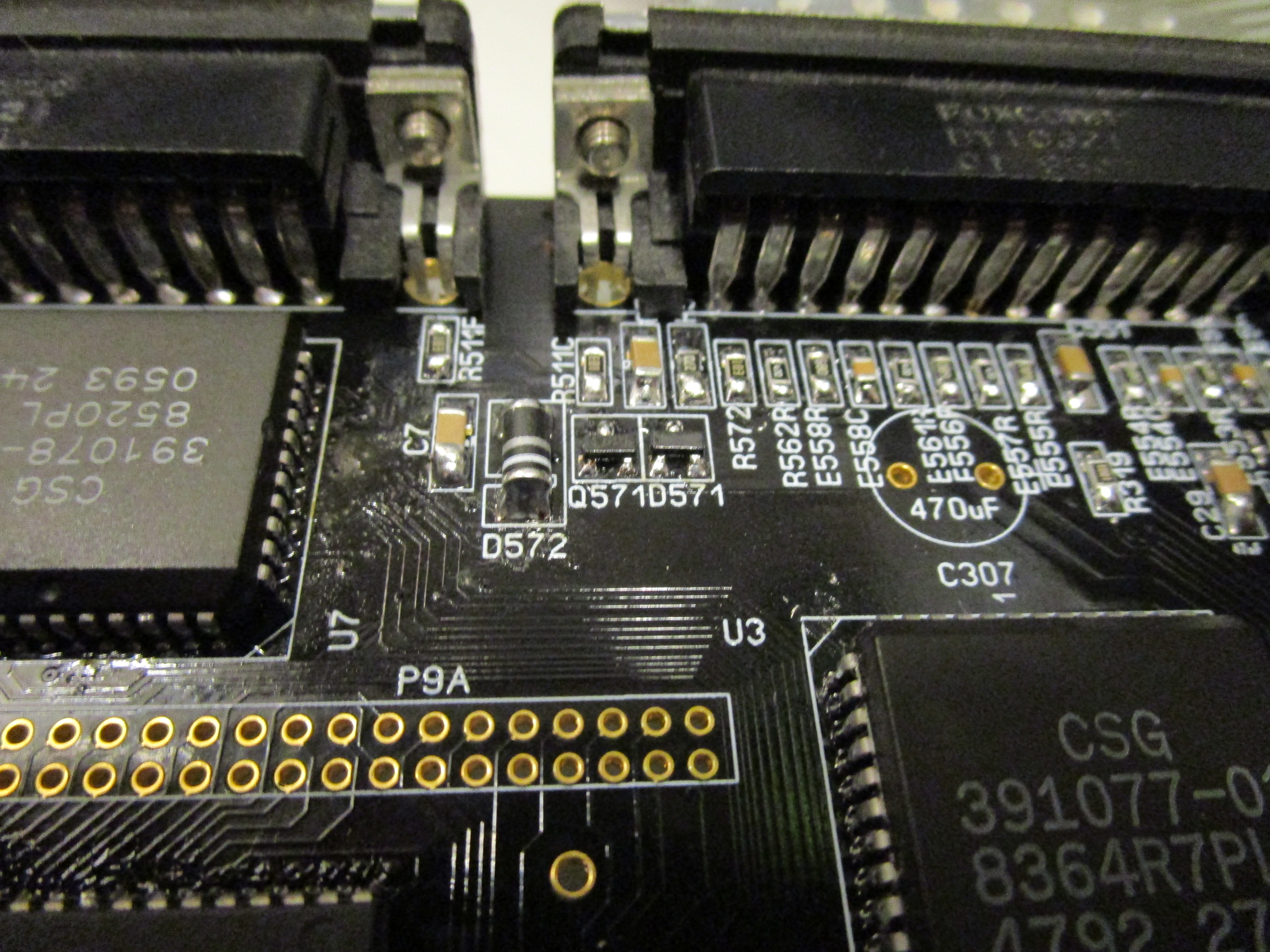
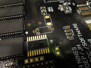
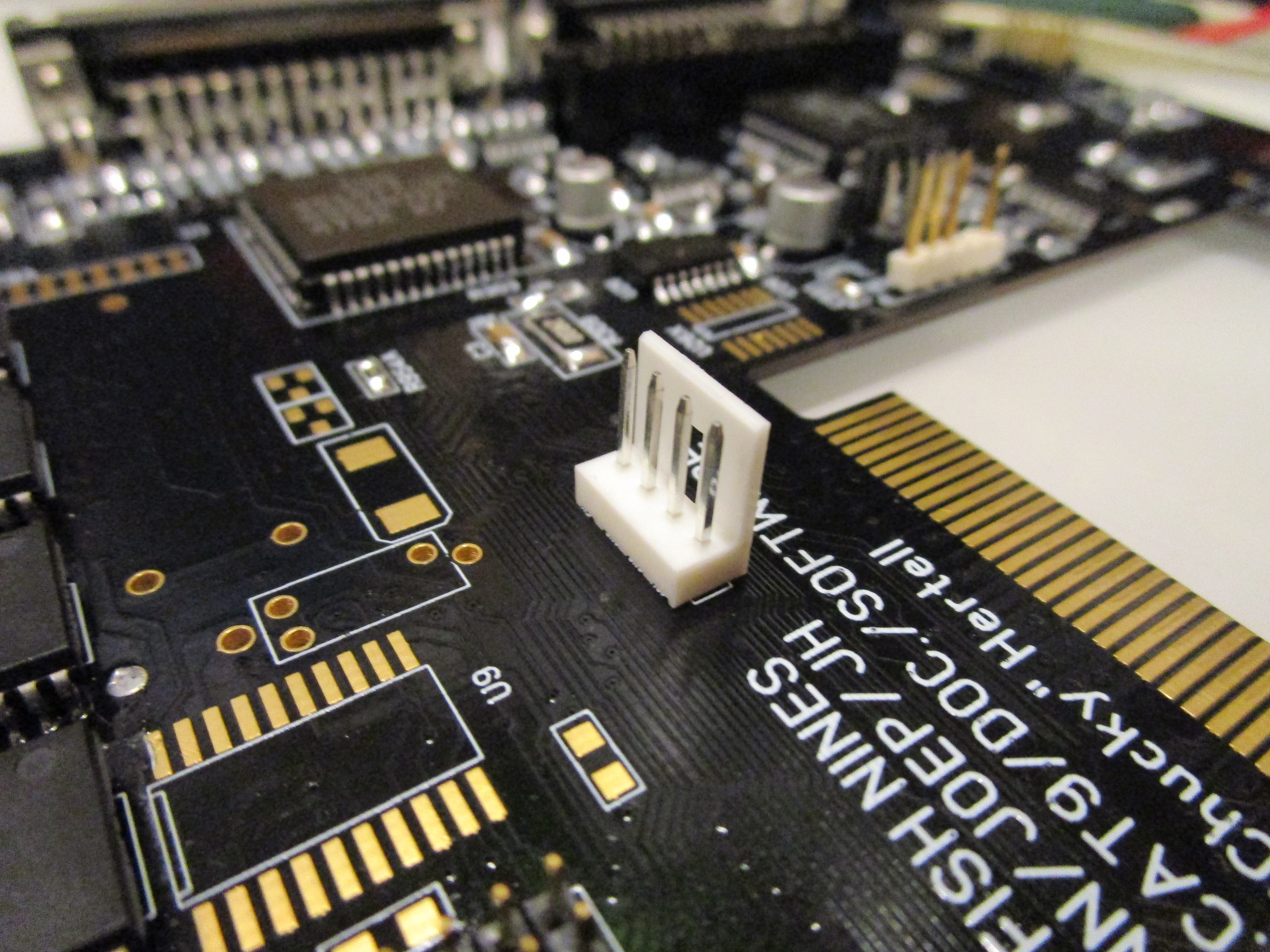
And then at the PCMCIA port:

Lets take a look at the shcematic again:
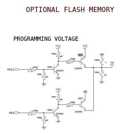
oh part of the nonsupported flash option. so. THIS can sure be skipped. Will be removed in future.
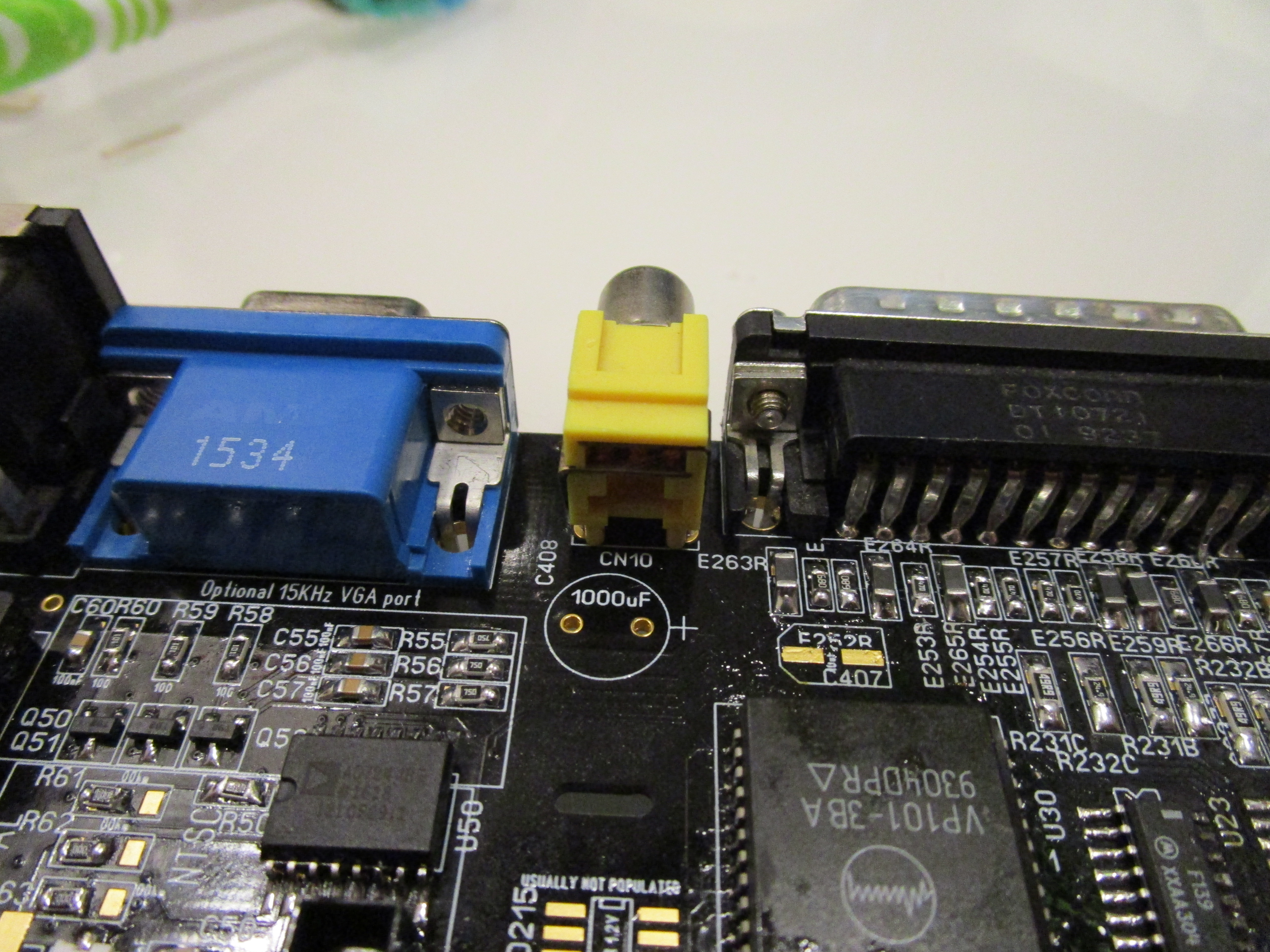
now all “normal” A1200 stuff is done. Lets talk about “extras” and lets begin with the Composite/S-Video:
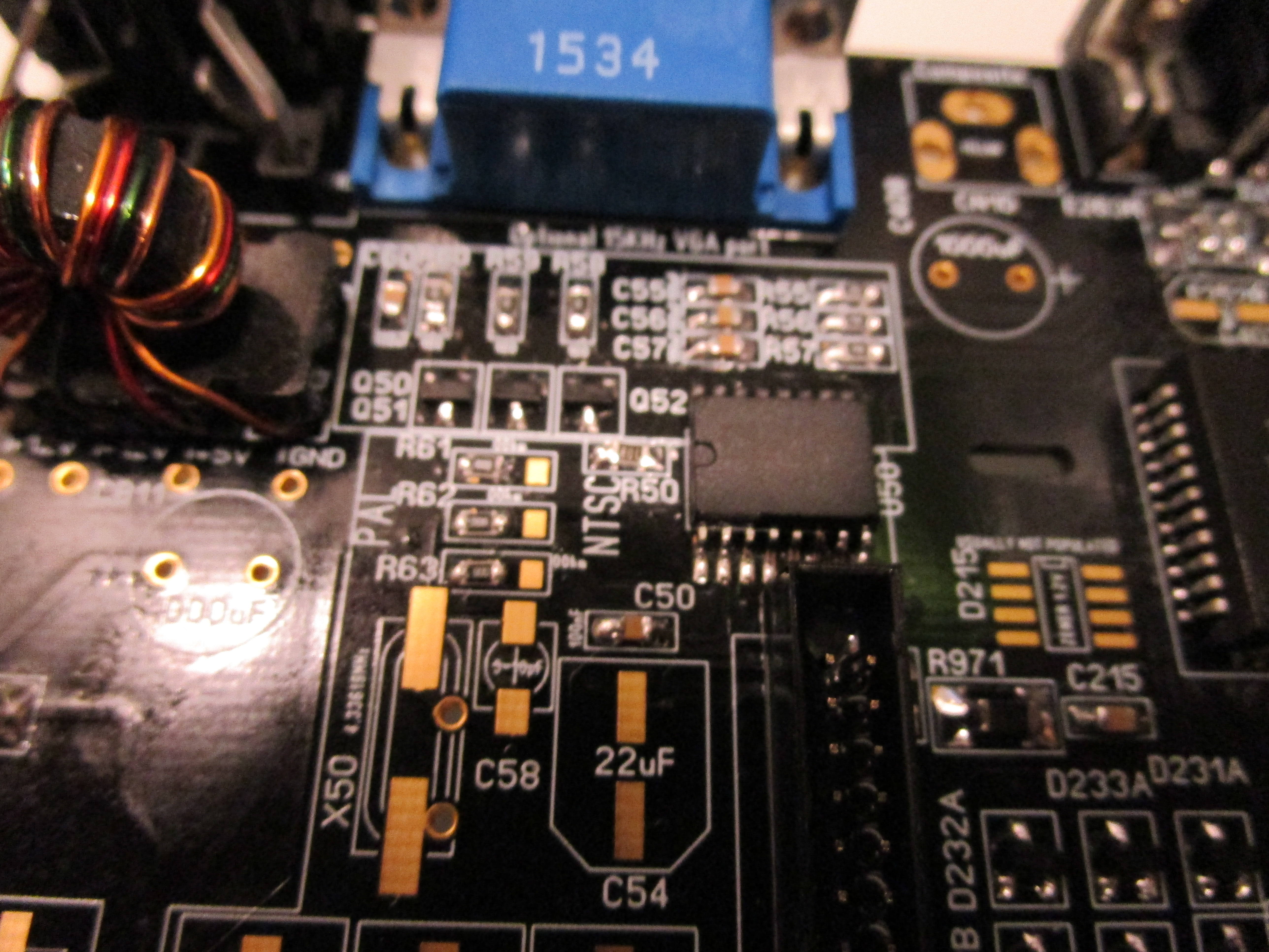
First of all before talking about the AD724 I have populated above the IDE Connector.
you can see 3 0ohm resistors that selects either PAL or NTSC. this is configured for PAL.
the Bottom resistor R63 tells alice what mode to start in as default. the other 2 is for the composite chip and timing.
so you MIGHT want to put a jumper or so on R63 if you want to be able to switch between PAL and NTSC screenmode.
(this however does NOT affect the PAL or NTSC Osciallator you have installed, the 28MHz one)
Well the AD724 is the chip doing the composite and Svideo. instead of the obselete CXA chip on the A1200.
Now you need to populate the trimmable CAP. (THIS you can skip if you are using NTSC mode on the 2 top 0ohm resistors)

Here it is installed. AND I also installed the 22uF electrolyte.. (that cap is needed even for NTSC but not the trimable one)
and the oscillator. you can either take one off the A1200 board or add a new surfacemounted version. I have one from an old A1200 board:
(this can ALSO be skipped in NTSC config)
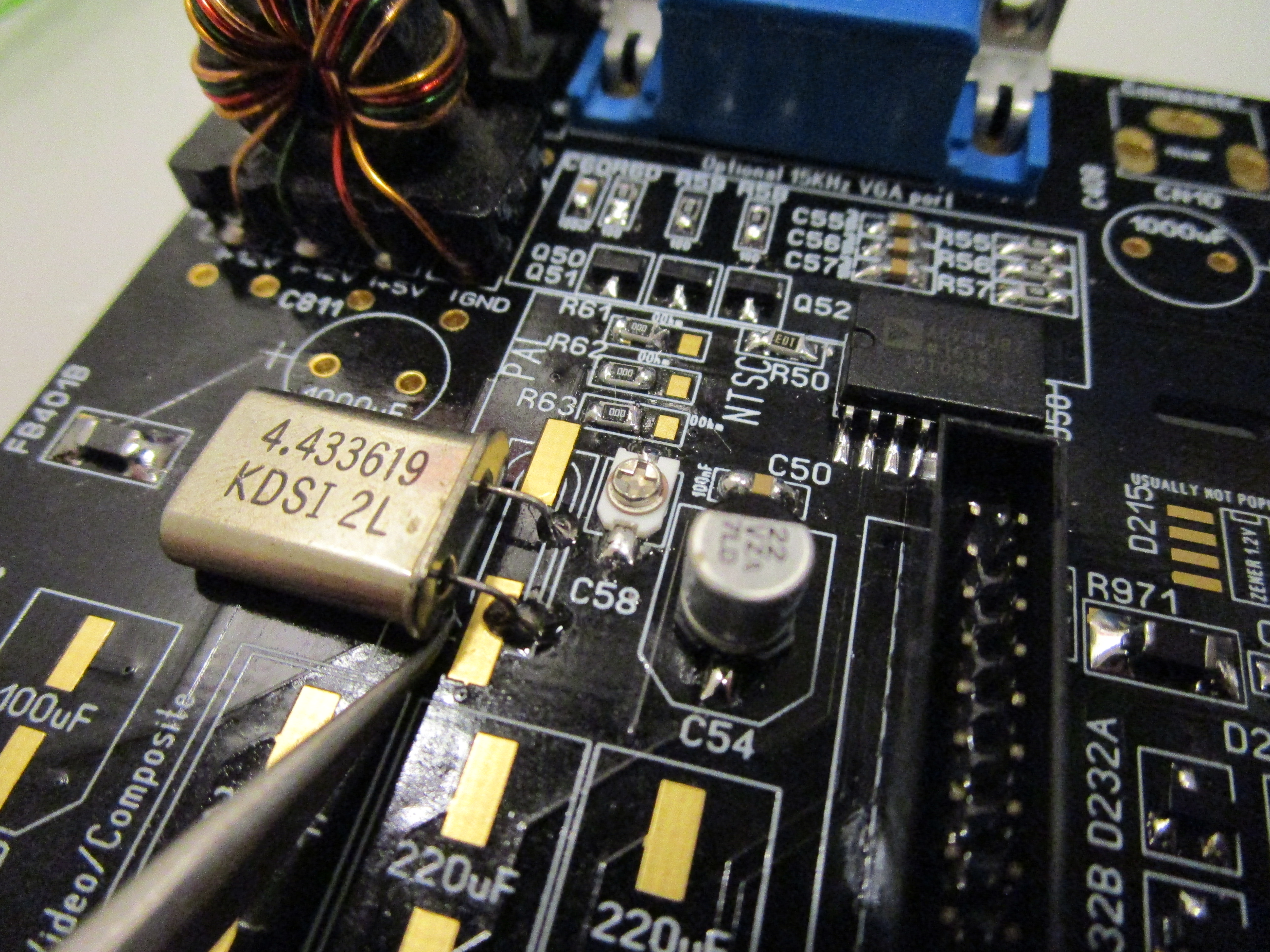
make sure the oscillator does not short with the SMD pads opinted out here on picture.
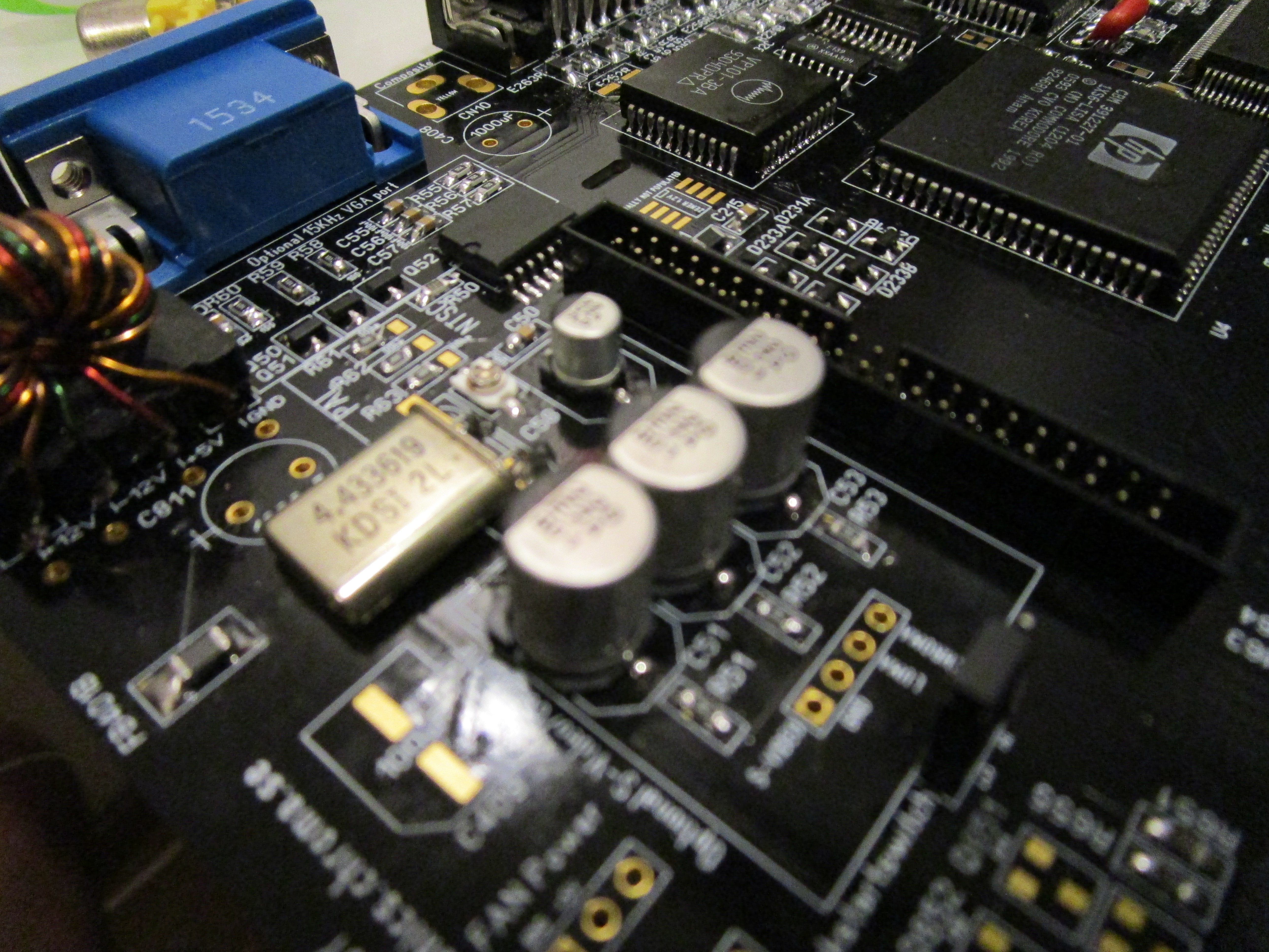
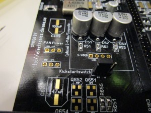
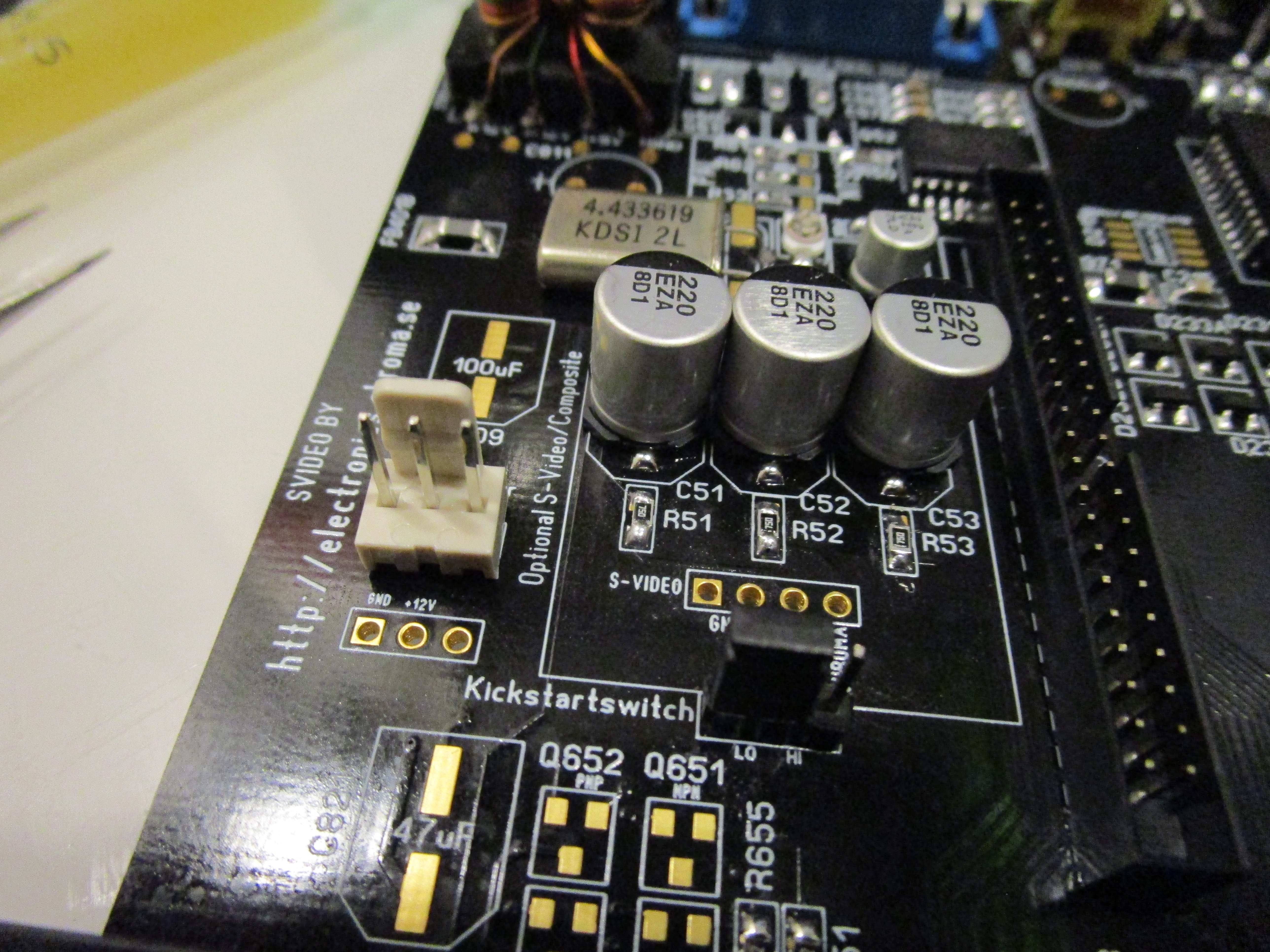
Now add the 220uF (huge) caps and composite connector. and you are done. the trim cap needs to be adjusted.
here there have been reports of issues. it seems that SOME trimcaps works better than others. will investigate in this.
NOTE: for Composite C53 is required. for SVideo C51 and C52 is required
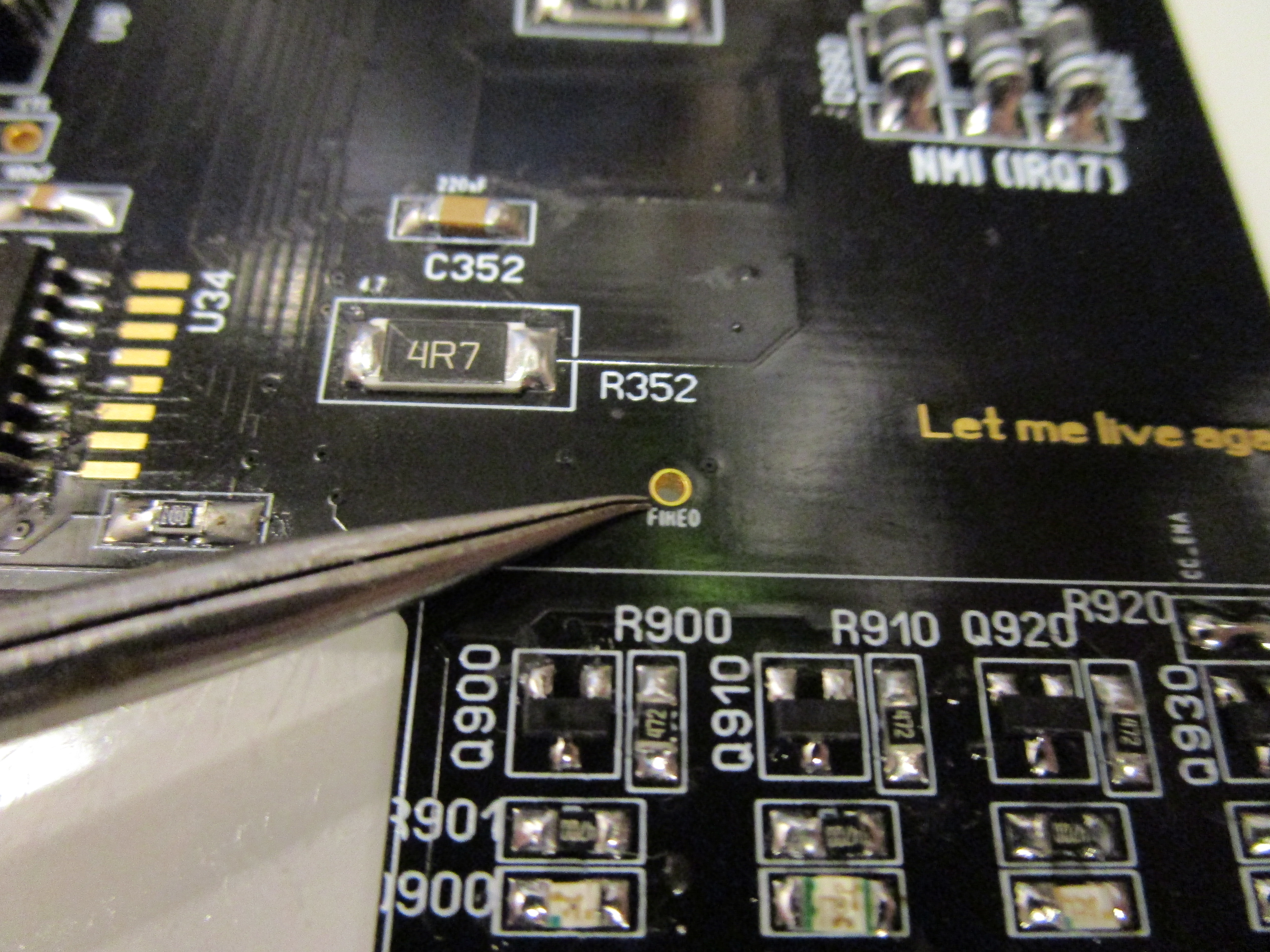
Now time for the NMI (IRQ7)
This is a handy tool for coders as some assemblers (asmpro etc) can enable a IRQ7 function that makes it possible to break eternal loops etc.
also software for “freezing” similiar to the Final Cartridge on the 64:
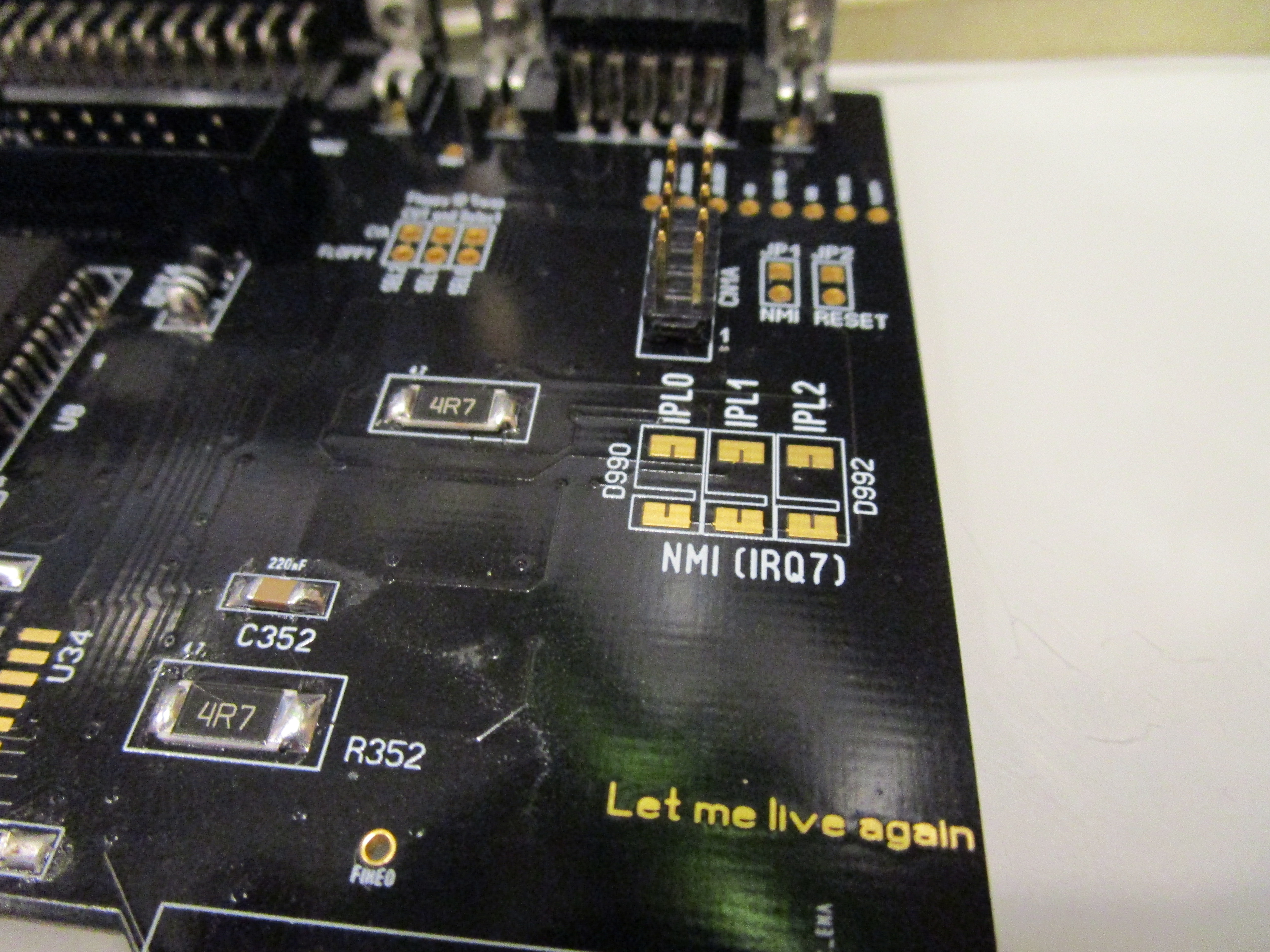
Add 3 diodes and the switch header:
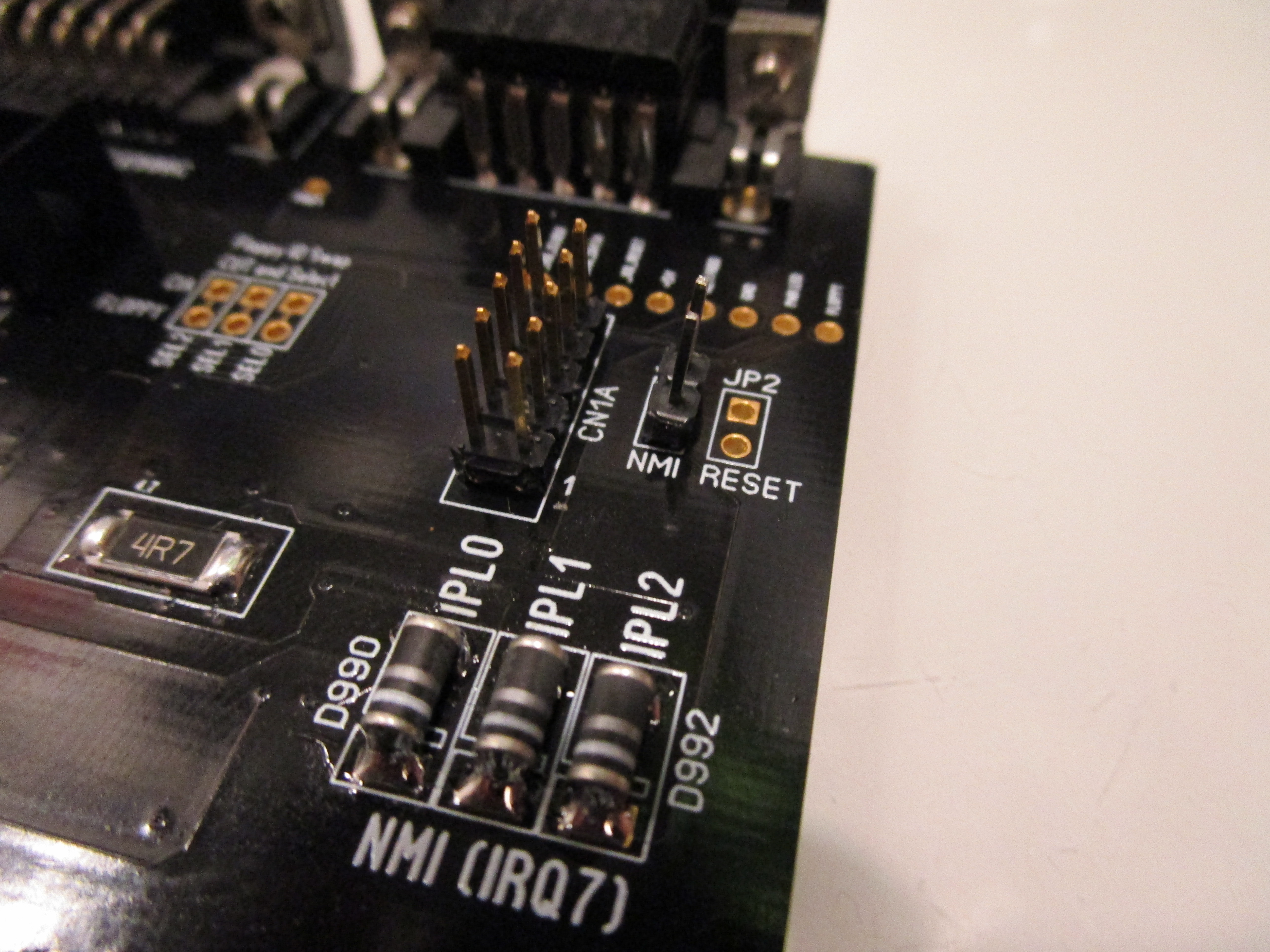
When you short NMI you trigger a IRQ7.. if no software handling IRQ7 is installed. you will notice that the machine just will pause when the button is pressed.
And when we are at it: add a Reset header

Shorting this and the machine will simply just reset.
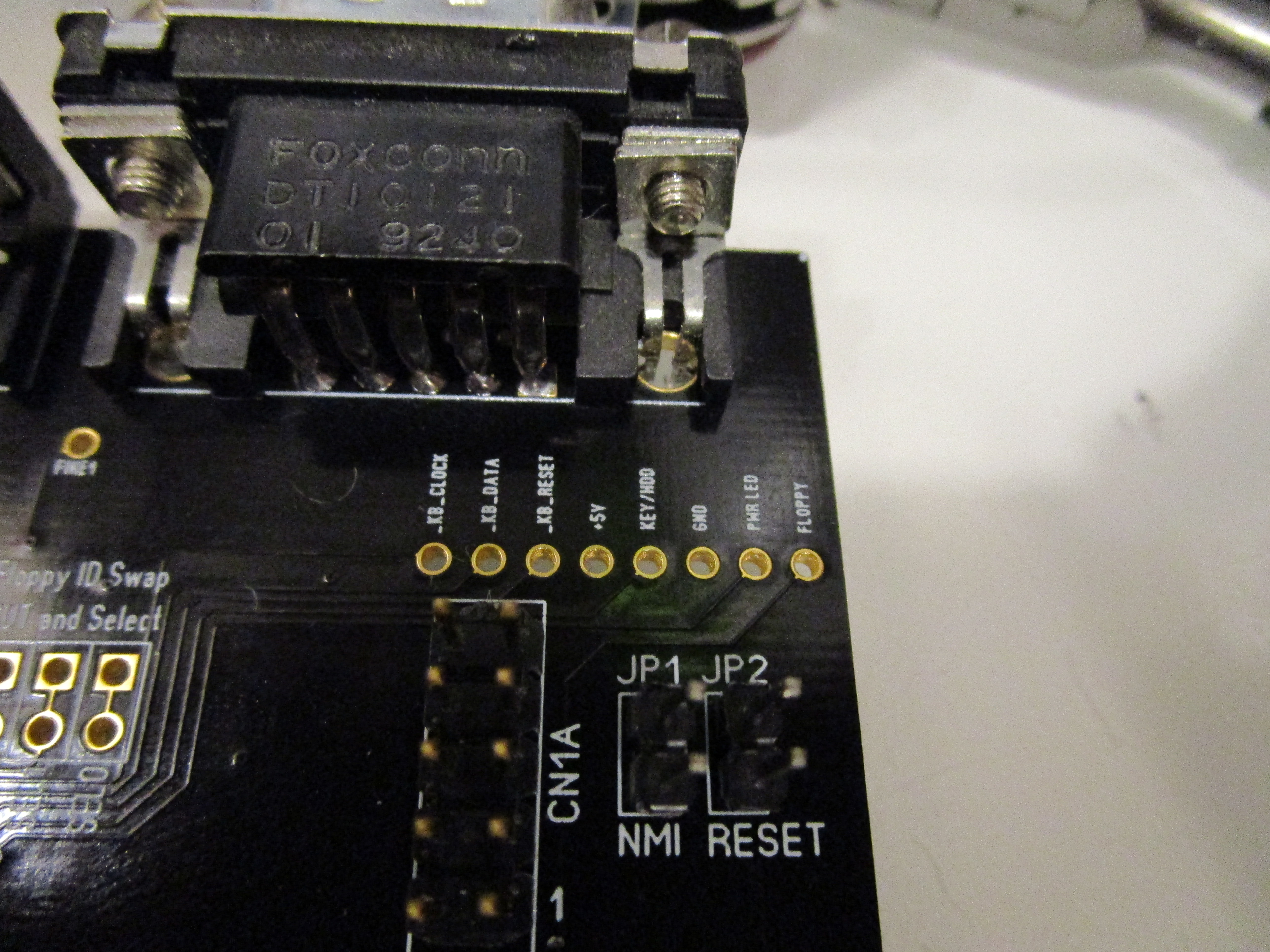
Now we have the Floppy SEL pad:

Usually you do not do anything here. but if you do want to have the possability of swapping DF0 and DF1. like having a gotek externally but want it to be df0 and the internal drive will be a df1. you can cut the trace between the holes and make a switch that swaps the positions of the SEL signal. more or less like: DIY Boot Selector
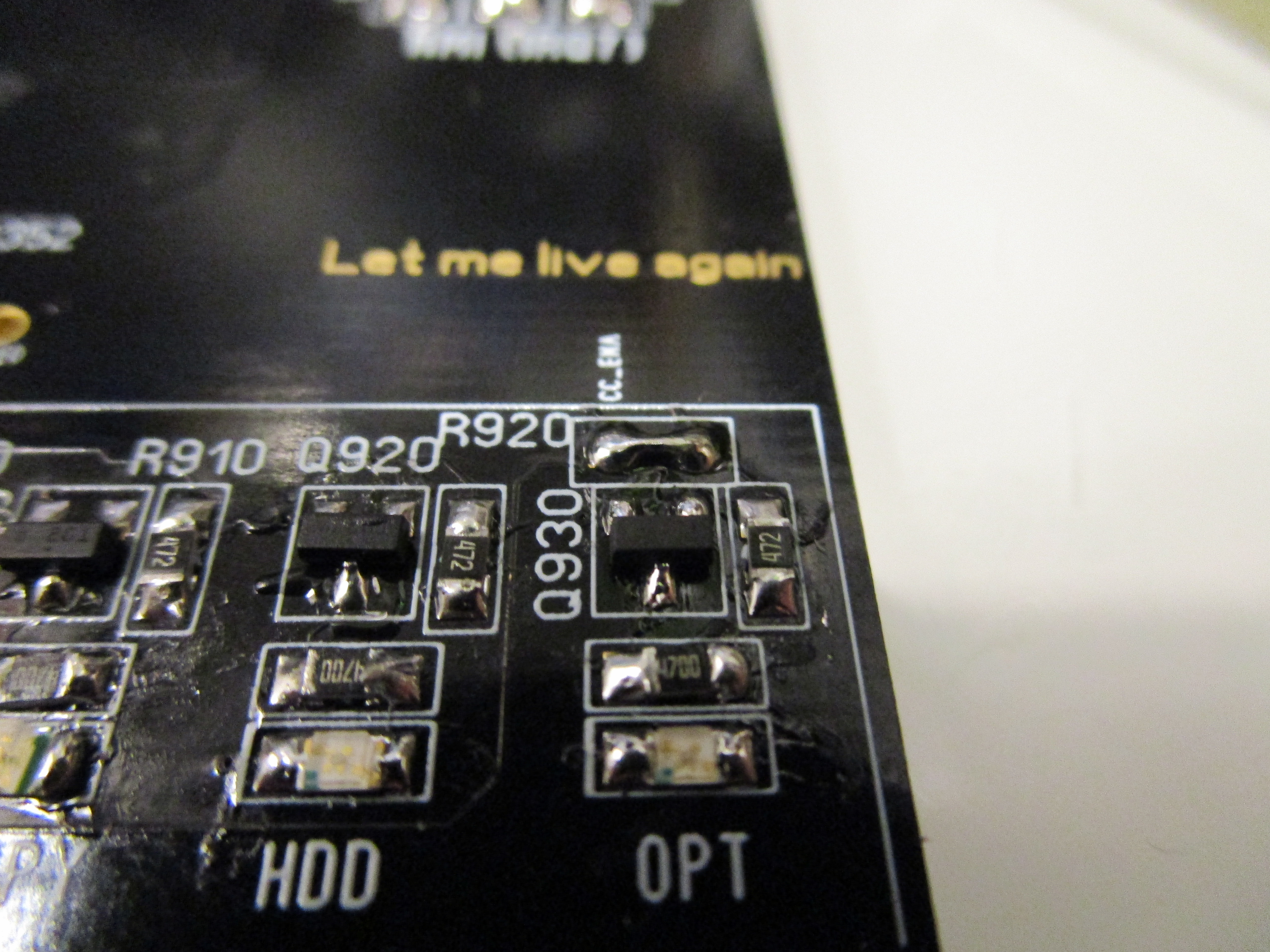
ok LED. “optional”
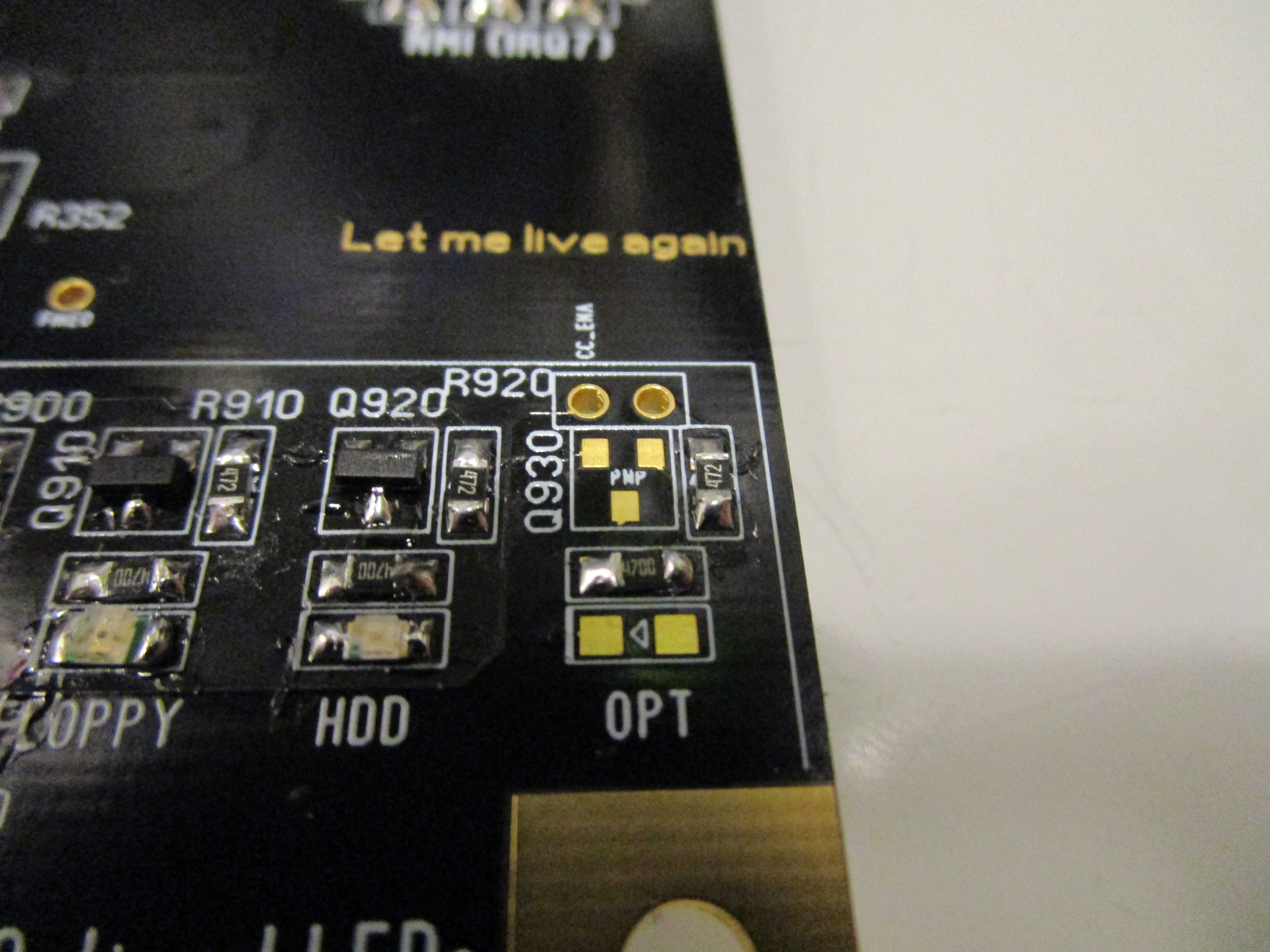
this is a special led. it is not really connected anywehere. you can see a header at the top. this is input and output. the right hole is the input to the led. technically you can put in a led here and solder a wire to the right pad and to anywhere you want to trigger the led.

Here I installed the led and PNP transistor. most people I guess want this to be connected to PCMCIA activity. and that is actually the left hole. so by bridging those holes. “OPT” gets to be PCMCIA activityled:
BUT first you will need to add 2 resistors close to the floppy powerconnector:

R637 should be a 10K and R638 should be a 4.7K:
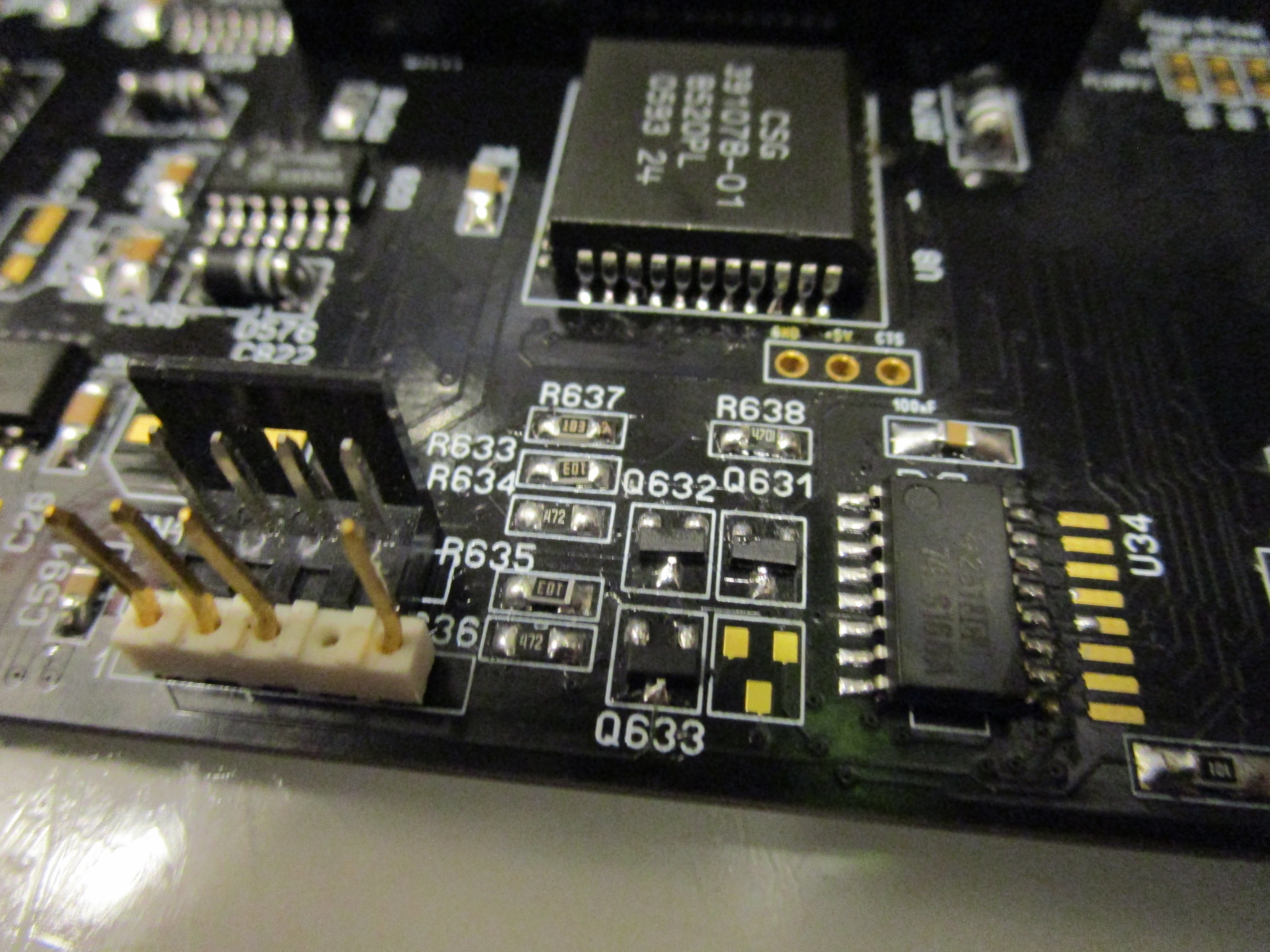
Now it is done. if you populate the empty location with a PNP transistor. that signal will also be present at the hole for the led board that is not connected here. (like on all A1200 actually)
Then we have the A500 keyboard connector:
but I MUST confess. I have never really tried this 🙂
we also have 2 mystery holes:
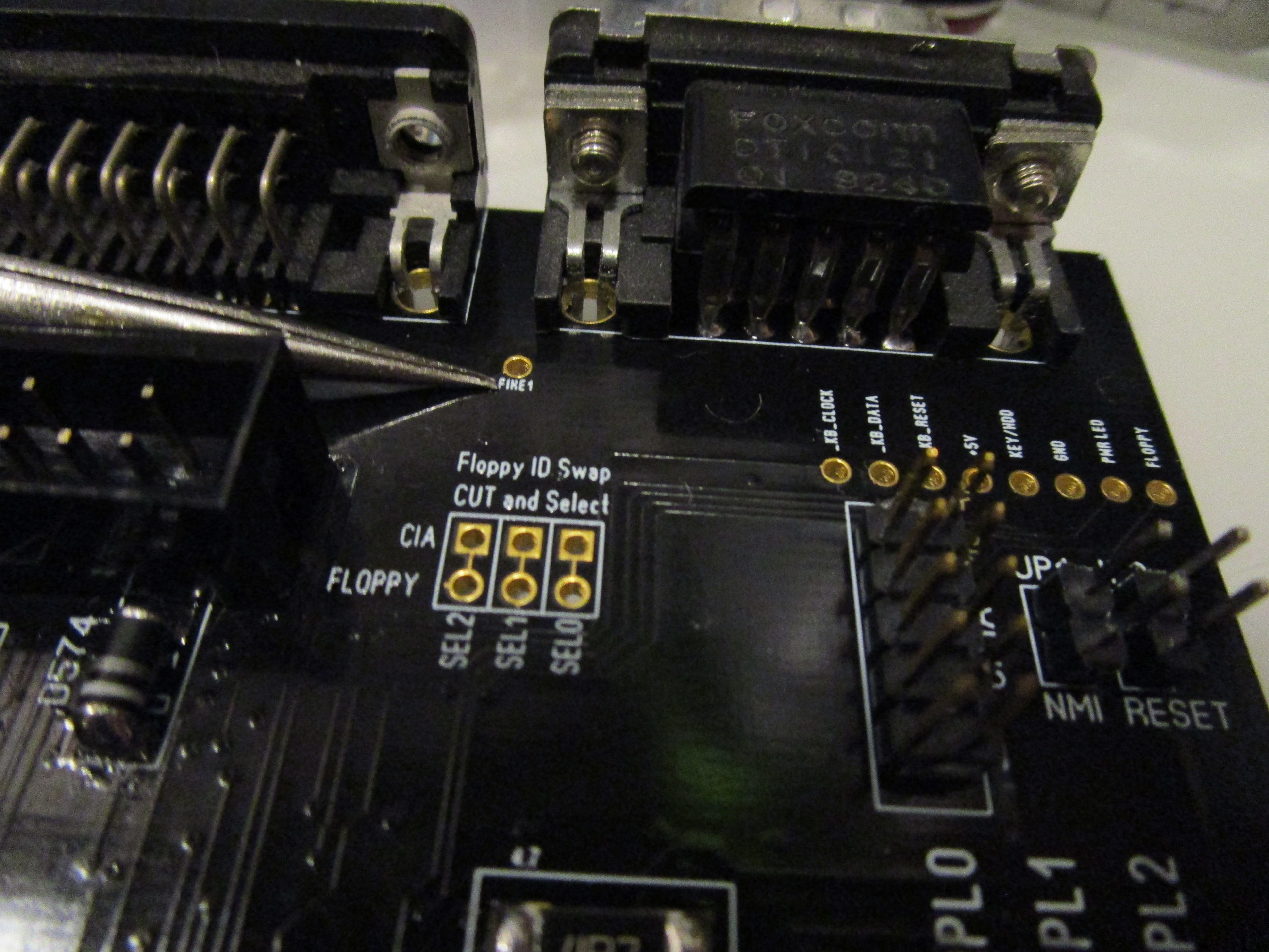
This is “fire” button of port 0 and 1. I did put them here to be able to access those signals if you want to do a automatical kickstart switch or so based on those.
We also have FAN power:
Here I populated the 5V port with a PC style fan connector. 5V to let the fan run more quiet. (some fans does not work at 5V)
and to end with we have the extra powerconnector:
This can be used to get power to something you need. OR ADD extra power to the PCB if you have a BPPC+BVision where it is recomended to add extra power close to the CPU connector. (also in the manual for the BPPC/BVision)
All done.. put all electrolytes in place. ready for ultrasonic:
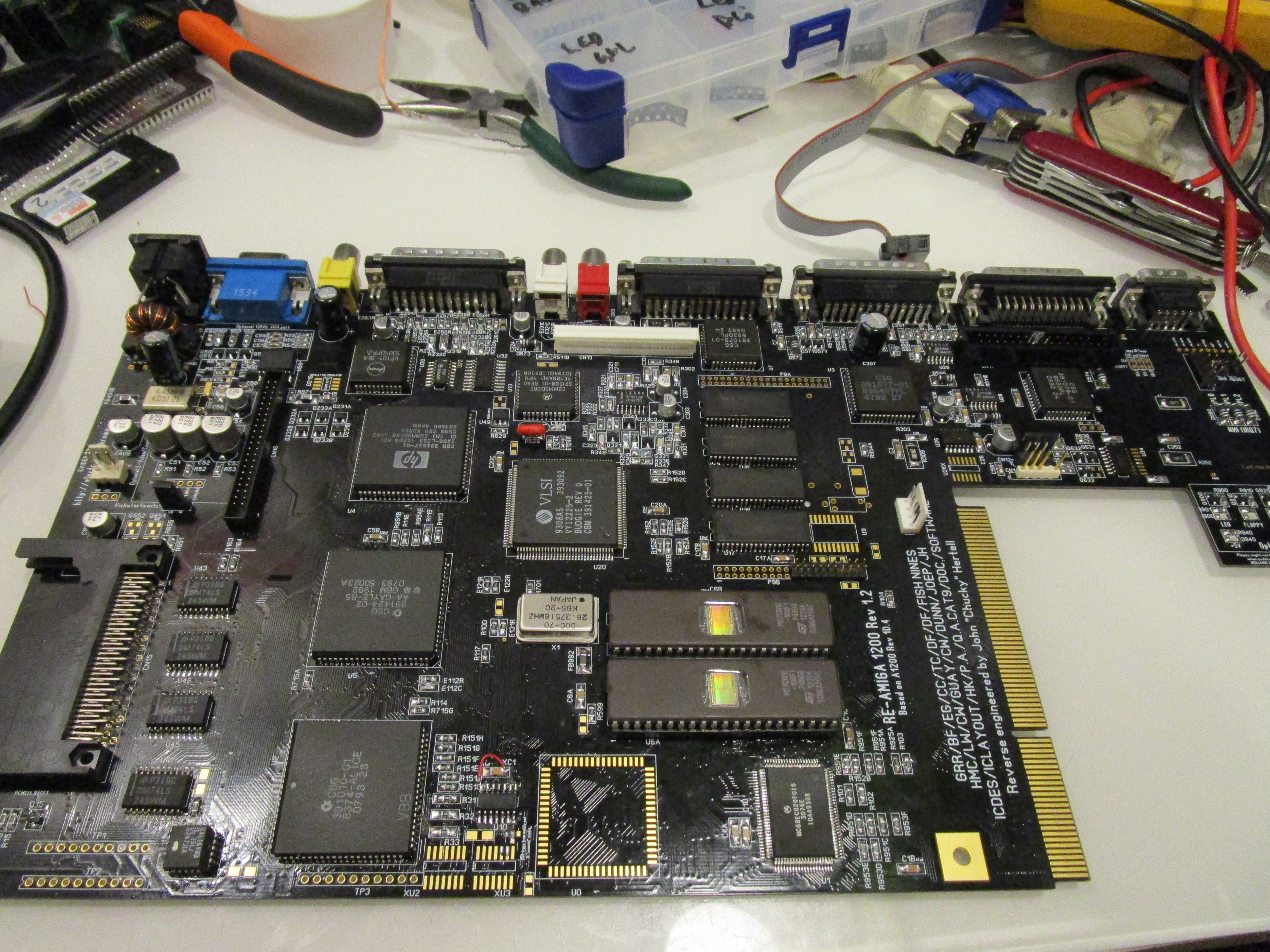
Proms with Kickstart 3.1 and Kickstart 3.1.4.
OHH! and the ROUND DIN? Here is the pinout for power:
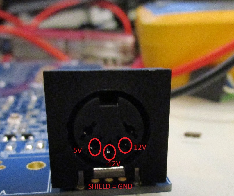
outer pins, not used. In early versions I had double 5V lines. this however was a misstake as pins for the square would make a short to ground.
pin to left here, 5V, middle -12V and to right 12V. Sheild is ground
I have a problem, the D900 diode is blinking, and the green screen is showing.
then chipmem tests in diagrom should fail. check for bridges.
All memory connections chip, bridges are ok, memory checked in the s3trio graphics card
It can also be bridges at budgie and the GAL making this.
you should run diagrom on serial output and see the result
I have the same green screen. I used NOS AGA chipset, NOS ram chips thinking it might be my old ram chips. Checked all solder connections for bridges, none found. I have REV 1.0 RE-Amiga board if this helps. I tried DiagRom but i do not get a clean signal from the serial port even with a NOS Paula.
no clean signal from serial port. this is a indication of a short somewhere.. when tghis happens. I have learned to remove ALL ram chips. if you get a serial output then. then add chip by chip as in my description
Restarted with a rev. 1.2 and i had the same symptoms. Rechecked all the solder joints and found some not so well soldered ones in the AGA chipset. I re did them ALL and now a have a working reAmiga 1200! Thanks alot!!!
Thank for your reply Chucky. ‘l’ll try your method.
I am not sure if it’s related to the problems you guys are having but it was pointed out to me by the guy who did mine that the 100pF capacitor Mouser code in the BOM is wrong, it links to 0.01uF capacitors.
should not be issues even if the value is off..
It certainly gives an issue. If you don’t belive it, replace all the capcitors with wrong values and your board does not boot anymore.
Hi, I have a problem. I have fully populated the amiga, and when I power the board – withoud anything attached, I get a white screen, so I do not think the kickstart kicks in :-). What am I doing wrong?
Well what does Diagrom say?
I did not succesfully flash the diagrom, will try it again. I tried to power the amiga with and without kickstart, and did not see any different results. Both I get a white screen.
Reflashed the diagroms, but same result. I actually have made 2 boards, both have the same issue, there must be something wrong in my actions. I used existing chipsets, including GAL. They come from two different PCB’s: one with videodac with zenerdiode and one without zenerdiode. Please help!!
Hi Chucky, everything is working so far except for the mouse. The buttons are working but it does not move the cursor. I checked for voltage and it get +- 5V. Tried a joystick and Joy port works. I know they do not send the same signal but what i want to know is what chip catches the mouse up and down movements so i can troubleshoot it. i’m not too good with schematics sorry.
Thank you.
Juan
Not the cursor but the pointer, sorry.
I was troubleshooting my mouse up and down problem and found out that U34 is not connected to ground on pin 8. I have a 1.2 board. Though it did not fix my problem.
Ground is ground. If the chip is connected via pin 1 (which it is), there shouldn’t be a problem. To see what I mean, you can take a continuity test between pin 1 and 8. If both are ground in the chip’s pinout you will see that they are connected internally.
However, I’m having the same problem as you: Mouse buttons work, but movements aren’t registered. I’ll investigate this further.
Best,
Torsten
Hi Torsten, did a continuity test and pin 1 and 8 have no contact between them. Compared my rev 1d4 and 1d1 boards that i have and pin 6 and 8 are grounded but not on the reamiga. Maybe it’s a manufacturing fault. But I’m not blaming anyone, this project is too much fun!
Thanks for helping out.
The pins 1 and 8 are not connected internally, you can measure that yourself. There is no ground on pin 8, and there is no ground on pin 6 either! The ReAmiga gerber has errors.
Hi Juan,
of course, you are right – there shouldn’t be a direct internal connection between pin 1 and 8. Just my bad.
And you are right that only pin 1 is grounded on the ReAmiga, and pins 6 and 8 are not. They are only interconnected. And there’s a via from pin 8 obviously going nowhere. I think that’s where the ground connection was supposed to be. I don’t think it’s a manufacturing fault. The connection is missing from Chucky’s original Sprint file, too.
I’ll try mine with a jumper wire from pin 8 to ground and see if it helps.
Best,
Torsten
Ok,
meanwhile I tried the following:
– Bridge Pin 1 and 8 with a jumper wire -> no change
– Remove the 100 nF capacitor, Chucky placed between VCC and GND (Pins 1 and 16) -> no change
– Checked even CIA and Lisa again for bridges and bad soldering and redid some joints -> no change
– Checked the CCK_A and/or CCK signals on both Alice, Lisa and U34 -> Looks just as it should (slow ramp up and fast down slope at approx. 3.5 MHz)
At the moment I’m out of ideas.
Chucky, can you say something about it?
Thank you,
Torsten
Btw., I’ve had to remove the jumper wire between pin 1 and 8 of U34. For some reason, putting pins 8 and 6 to ground couples +5V and GND with a very low impedance of about 20 Ohms.
Mouse works flawlessly, even if pins 6 and 8 left floating (or better: just connected to each other).
However, my floppy problem (s.b.) remains. According to my oscilloscope, +5V goes down to 4.8 on occasion and there’s some ripple, too.
I’ve already ordered a Meanwell RT-50B which has an adjustable +5V line and does provide 4 A on the 5V rail. Let’s see, if more juice fixes the problem… 😉
I dug further. The LS166 as well as Lisa seem to be ok. In particular, D0 through D7 on U34 are correctly pulled high by their 4.7 k pull ups on the backside of the board. If I connect, one (or more) of the pins to GND manually the respective direction(s)/firebutton lights up in DIagROM…
Oh there have been action here. I have been far too busy with my ReAmiga 3000 work.. 🙂
ah mouse can be wrong! there was a fault in the BOM! the 4.7Ohm resistors to the power for the mouse. in the original BOM they was 4.7K instead of 4.7. this can (will) make the mouse behave wrong!
Ah, Chucky, thanks. Looking at the original schematics, this should be 4.7Ohm for both of the BIG resistors near CN1A and U34, right? I stuck 4.7k in both places…
Thank you guys for the info. I will be changing resistors and hopefully see a sign of life.
Juan
It’s now working swapping the resistors.
Thanks alot!
Juan,
good to know. Will swap mine next week, as soon as the new ones arrive.
Best,
Torsten
Thanks Torsten, will be ordering new ones too because I tested with old resistors from a dead board.
Thanks again and have fun with your new Amiga.
Juan.
Ok, I changed the resistors and mouse is working fine now.
However, I stumbled across another problem now:
The ReAmiga won’t boot from floppy. At least not from a real one.
To explain further:
I connected the internal drive (it’s from my original Commodore A1200 and worked there up until I last tried). It makes the usual clicking noises and upon bootup, the floppy LED flashes. The drive motor is starting to spin and the Amiga tries to boot. The screen goes purple (like the KS background) and after about 3 seconds of trying to read from the drive, the KS animation returns.
I also tried an Amiga 500 drive as internal – same effect.
Now for the funny part: I connected an external drive that doesn’t even bother to click or do anything. I then daisy chained to this seemingly dead drive an external Gotek USB floppy emulator. This one boots just flawlessly. And it does so, too, if I connect it directly to the 23 pin external floppy header.
I now have two suspicions.
Chucky, perhaps you can point me in the right direction here:
1) There is some power issue that prevents the real drive from working but doesn’t affect the Gotek. There’s a funny thing going on that supports this hunch: When I booted into workbench and insert a disk into the real drive, the screen eventually blanks several times, then workbench utters a read error. My multimeter, however, shows steady 5.06 V on the +5V line.
2) Some signal does not reach the real drives that they need to function, while the Gotek is unaffected by that.
3) I am missing something completely here.
When booted to Workbench, I also realize that Alice gets reasonably warm to the touch. About 40 – 45 ° I’d say. Is this normal?
Thank you and best regards,
Torsten
I dug further:
After removing the jumper between pin 1 and 8 of U34, Alice doesn’t get that warm anymore – so that’s about that.
As for my floppy problems:
– I hooked up the internal floppy to my lab supply. It still doesn’t boot and I get read errors once booted into workbench via the Gotek, but the screen then stopped turning black intermittently while accessing the drive.
– Read errors often occur for blocks 56 and 60 which makes me wonder whether the drive is able to change tracks at all.
– Formatting a disk fails with “Error formatting track 0”, quick format bails out with a “seek error”
– And: Chosing one of the connected “real” drives (either DF0: or DF1:) to boot from in early startup results in red screen and flashing LED and often yellow screen afterwards. This is true regardless if both drives are connected or only one.
– Lastly: If I connect a CF card adapter with a 4GB card to the IDE port, open HDToolBox of OS 3.1.4 and read the configuration, it always reads a size of 260 GB…
Both CIAs and Gayle check out ok in DiagROM. However, I’m starting to be a bit suspicious about Gayle…
Ideas anyone?
Thank you,
Torsten
Hi Torsten, i have the same problem but with DF1: drive. The error is “Couldn’t format cylindre 0”. I tried various 1010 and 1011 drives but they give me the same result. I know this won’t help you but a least you won’t feel alone in this. hehe.
Juan
Thanks, Juan, that gives me some comfort indeed. 🙂
Btw., where did you buy your board from? Did it come as a kit with passives?
Best,
Torsten
Mine was only the motherboard from fleebay. I ordered my passives from Mouser.
Chucky,
could maybe C591 be of wrong value? My schematics says 10 nF, while according to the locator, I put 100 nF there. Does this even matter? Anyway, this would be the decoupling for floppy +5V.
Thank you and best,
Torsten
nahthat is decoupling only anyway so it wouldn’t really matter
I use that and had no issues with either internal or external drives
Juan,
just another question: What Budgie Revision are you using? I’ve build the ReAmiga with NOS parts, and got a -02 Budgie this way.
I don’t know if this matters much, but as it seems, Commodore modified the circuitry a bit for the newer Budgie.
However, I don’t think this has anything to so with my Floppy problem.
Best,
Torsten
nah. budgie doesn’t handle floppy.. only CIAs and Paula
Thanks for confirming this. I’ll probably try and desolder (or at least reflow) even CIA on Monday. Maybe there’s some hidden short. Maybe I should even put sockets for both CIAs. This way I can try spare ones easily.
Just for the record, i have a NOS budgie rev 1 and my expansion port is working fine with an ACA 1233n. I’m using NOS AmigaTech CIA chips but they are the same as the C= ones. Can CIA chips be partially broken? Because everything they control is working, except DF1:
Juan
Oh my, I now socketed both CIAs and Paula. Produced a short on the socket of CIA A in the process. Tried to pull out the CIA with a PLCC tool, but because of the narrow space between the socket and the parallel port ripped off half of the socket in the process.
I’m almost reluctant to desolder the socket and have a look at this mess. :-((
Now, in DiagROM both CIA tests fail, parallel port is almost completely BAD and left mousebutton (aka Fire0) doesn’t work. It certainly all comes down to U7, but I still don’t know, how many of the 44 pads are still kind of intact. At least, U7 gets warm to the touch, so the row towards the front edge of the board seems relatively unharmed.
However, I’m not sure if my skills will suffice to repair all this damage… 🙁
Sad to read… In the meanwhile i’ve found my problem. It looks like my new floppy drive that i have bought from amigastore.eu is at fault. When plugged in it makes floppies from df1: unreadable. So I just tried with an original floppy from my A500 and all works now.
Juan
Thanks Juan,
I may have been extremely lucky. Desoldered the U7 socket and found no apparent damage to the board. All pads I probed are definitely still firmly connected.
My guess is that the sockets I used are just crap. They apparently just sticked to the board but didn’t make a firm connection with the solder paste. I now ordered proven to work brown sockets and will try again as soon as they arrive.
Best,
Torsten
Ok, I’m back to field 1:
Both CIAs are socketed and pass all tests. Mouse/Joystick/Serial/Parallel are fully working. However, booting from floppy does not. This is true for spare Paulas and CIAs as well, so the chips don’t seem to be the problem.
I’m now again suspecting Gayle, since it has some bits of the floppy logic and IDE doesn’t work properly either. Maybe, there’s still some hidden bridge.
Off to the hotair station to desolder Gayle again. :-/
Fingers crossed!
Ok, I now socketed and replaced Gayle and replaced the Budgie. Still, I’m not able to boot from a real floppy or a harddrive, only from external Gotek.
What baffles me is that if I measure the resistance between GND and +5V, I get about 30 Ohms steady, while on my old Amiga 1200 1D4, I get a constantly rising resistance that starts at about 300 Ohms as you’d expect from a board decoupled by capacitors.
Chucky, is this normal? Do you have any suggestions where to look? I’m almost at the point where I’d order a new board and passives and start all over again…
I quite recently got information that one pin of the IDE connector is missing 5V. it is that one connected to the 4.7k resistor. the other pin on the reverse side does have 5V. so a small jumpercable might be needed. this might be the issue.
will try to get time to edit the erratapost any day.
Hi Chucky,
yes, I realized that when measuring all the signals on the IDE port. I’ll probably put a jumper wire between pins 41 and 42 of the connector.
My HDD problem is solved anyway – it was a cold solderjoint at the IDE connector itself. My cheap CF adapter doesn’t seem to care about the missing 2nd 5V linem, though
BUT, my floppy problem persists and I am now almost certain that the fault lies with a defective U26. Spare is already ordered, so we’ll see by the end of the week.
Best,
Torsten
Ok, U26 changed, still the same problem. Redid each and every solderjoint remotely associated with the floppy connector, measured each and every line of CIAs, Paula, and U26. Everything seems fine.
The only thing I can think of right now is taking the logic analyzer and compare the floppy access pattern between my working A1200 and the ReAmiga…
Btw., Chucky, the jumper wire for IDE has to go between pins 41 and 42.
I did some tests with the Logica Diagnostic ROM and think I’ve found something now:
When a disk is read or written, the _MTR0 line, coming from Gayle, is not properly pulled low. Instead is stays at about 4.5 V. Additionally, the _RDY line, coming from the drive, is never pulled low.
Since _MTR0 is also used for the LED signalling floppy access, that is my hottest candidate right now. I already changed all the caps and resistors associated with this line and removed Q632 but still no luck.
Strangely enough, both _SEL0 and _MTR, coming from the CIA behave as they should. However, I doubt that Gayle itself is the problem – I rather think, some low resistance somewhere and/or a short with another line is holding the signal up.
Don’t know what to do about it right now, though. ;-(
Mystery finally solved. I abandoned my first ReAmiga board, bought a new one and started from scratch. Et voilà: Floppy working perfectly.
So, I guess all boils down to some advices:
1) Don’t go with LOW quality PCBs for tasks like this!
Obviously, there are some people out there who take the work of others (others meaning Chucky in this case) and try to make a quick buck out of it. My first board had HASL coating, no ENIG. If you get something like this from a seller, return it!!! It will give you all sorts of trouble!
My second board has ENIG coating. Much easier to solder, much less bridges, much better overall quality. Also, the soldermask stays on while scrubbing the board with IPA and ESD brush.
2) If you are doing the board with solder paste and hot air (like I did), don’t apply LOTS of solder paste!
In the first attempt, I’ve been swamping the pads in solder paste using a siringe. The result often seems to look pleasing, but there tend to be hidden bridges and bad stuff everywhere.
In this second attempt, I bought myself a cheap used Silhoutte Portrait cutting plotter. I then used the Gerbers and a tool called gerber2graphtec to have the plotter cut SMD stencils for the whole ReAmiga out of old overhead projector films. This was a cheap but VERY effective way to get almost perfect solder joints. I’ve had not a single bridge and only 2 cold joints on the CPU.
I used a tool called gerbv to manipulate the Gerbers and remove all the big chips (and all the pads that are not to be populated) first, so I could do the birdseed and small logic chips first. Then I cut out the stencils for the large chips to fit beside the populated birdseed and did one chip at a time.
3) Take your time and practice first!
This wasn’t my first SMD soldering experience, but I learned a lot about being patient and going one step at a time while doing this project.
Just my 2 cents
Torsten
Hi Chucky,
Thanks ever so much for all your hard work on Diag ROM – it’s fantastic!!!!
I did discover a bug or deficiency in the RAM test routine (using v0.9 – not sure if it has already been fixed). I found that if the addressing of one of the DRAM chips fails, it can pass the test OK. A good way to test that is by fitting a 4164 chip instead of a 41256 (to a rev 5 or rev 3 500, or rev 4 2000) – as the 4164 lacks A8. But it will pass the test OK when it shouldn’t. However, Kickstart does detect the error.
Guessing a more extensive test using bit patterns across multiple locations would highlight an addressing related issue like this.
Thanks for creating and updating it though – amazing stuff! Just wanted to give you the heads up before my video goes up next weekend.
I know addresserrors isn’t handled. will think of a way to handle that “soon”
Just wanted to say THANK YOU to Chucky for this awesome board.
It runs rock stable with Blizzard PPC, Indivision MK2cr, IDEfix, Mediator TX, etc. in my tower setup. Just the replacement I wanted for my instable original board.
I also designed an opensource Kickstart relocator (including the Kickstart switch functionality Chucky built in to the board, but configurable without soldering, and a header for Matthias Münch’s clockport expanders) which I’ll introduce when I finally find the time to the major community forums.
It can be soldered directly to the ReAmiga board and displaces the Kickstart sockets from under the Mediator to make experimenting with different Kickstarts in towered systems much more pleasant…
You are welcome. glad you like it..
that kickstart relocator sounds nice.. 🙂
I opensourced the Kickstart Relocator – still lots of room for improvement, but works: https://github.com/tkurbad/A1200_Kickstart_Relocator
Sorry posted in another thread, but was looking to order any RE1200 PCBs if you still have any? Thank you!
I got boards you can reach me at johnhertell.nu
Hi Chucky
Could you please tell me where I can buy this motherboard?
I would like to start this adventure
Tank you
Hi Chucky , good morning
I would like to ask you some questions in relation to the following components:
1) 2N 3906 transistor can I replace it with MMBT3906 or with the BSR18A?
2) can I replace 2N3904 transistor with MMBT3904-TP?
3 MFP102 transistors can I replace it with BFR31?
3 Can IC’s 1488 and 1489 replace them with SN75188DR and SN75189DR respectively?
Thanks in advance
Hello Chucky good mornig
I have a REAMIGA 1200 Rev 1.4 card. in your latest Rev 1.5 you spoke of “Fixed a short circuit signal to VCC in Rev1.4 (C0D)” you could kindly explain to me how my card is updated.
Thank you
http://wordpress.hertell.nu/?p=710
there you can see at the bottom where the issue is and how to fix it
Hello Chucky
good evening
I am building a Re-amiga rev 1.4.1 board. I would like to ask you if I can mount the Budgie rev 1 chip instead of rev 0 without making any changes to the printed circuit.
Thanks in advance
Chucky,
I have a very strange problem.
After building my rev.1.4 board fine, my Amiga 1200 worked perfectly well for a few months, after which I just shelved it for a bit to use my desk for something else.
When I pulled it back out of the closet to use it, nothing, blank screen.
Looking at the PCB board, I only see a solid red light at D940. Nothing else.
Sometimes, D900 led lights up very briefly, and very seldom, it stays on.
Connecting the board using Diagrom via Serial (which used to work 100%) now produces nothing.
I checked the Odd CIA solders and they seem okay.
Any particular area you can point me to, Chucky ? I am at a loss.
Thanks
sorry it could be like “anything”..
Transfered to board v1.5 and all is well now 🙂
Hi Chuck,
I just finished building my rev 1.5 board. It’s working flawlessly. I would like to thank you for your work on the board and this guide.