OK we now have chipmem working in DiagROM.
To get serial INPUT to work add U305 (1489)
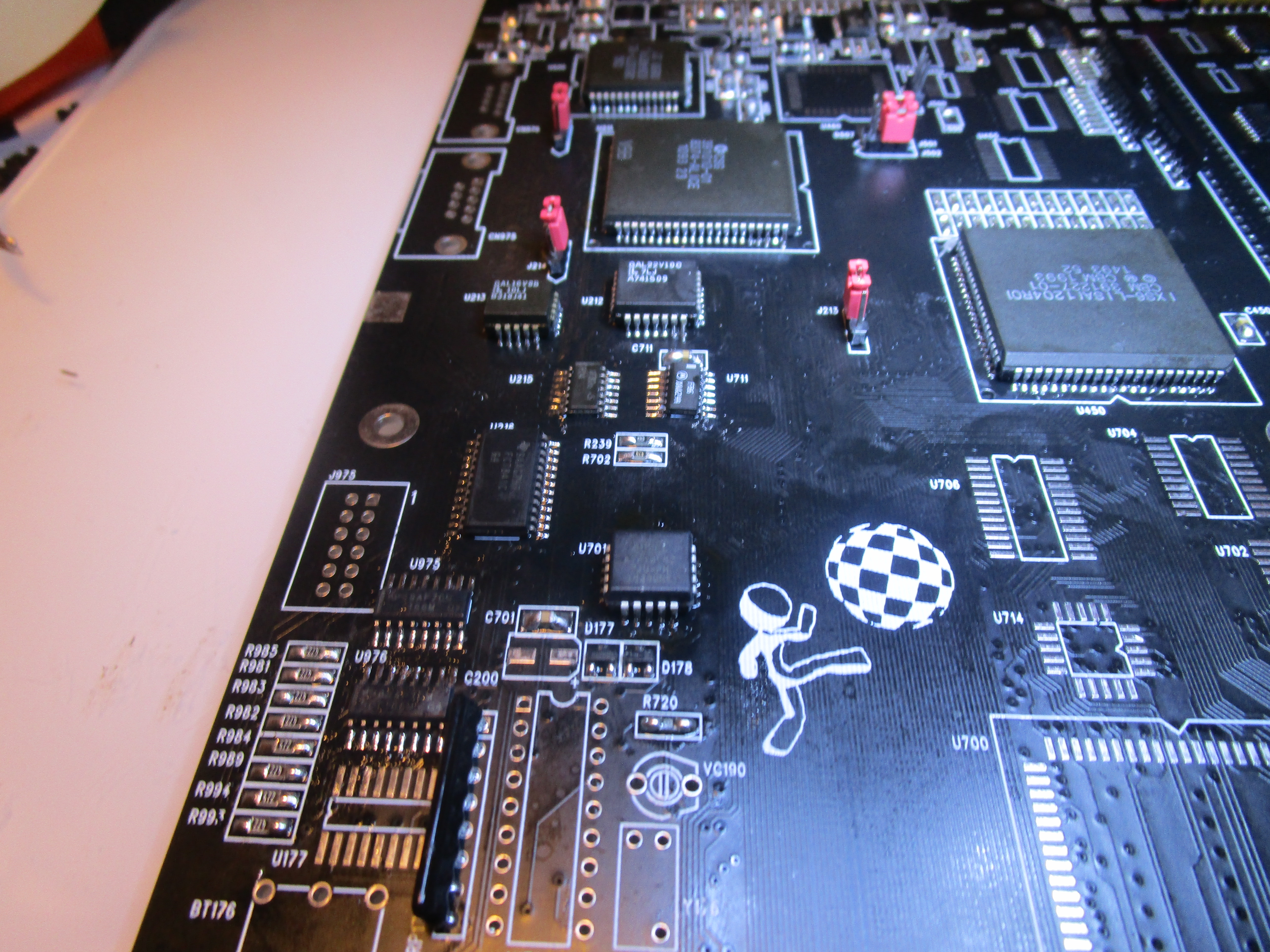
To fix some clocks etc add U215 (74F04), U710 (74F08), U205 (74HC4066)
and now to get IRQ tests to work in DiagROM:
Add U711 (74F86) and U701 (GAL)
Now IRQ tests will work in DiagROM, and now the machine should also start without the reset-magic
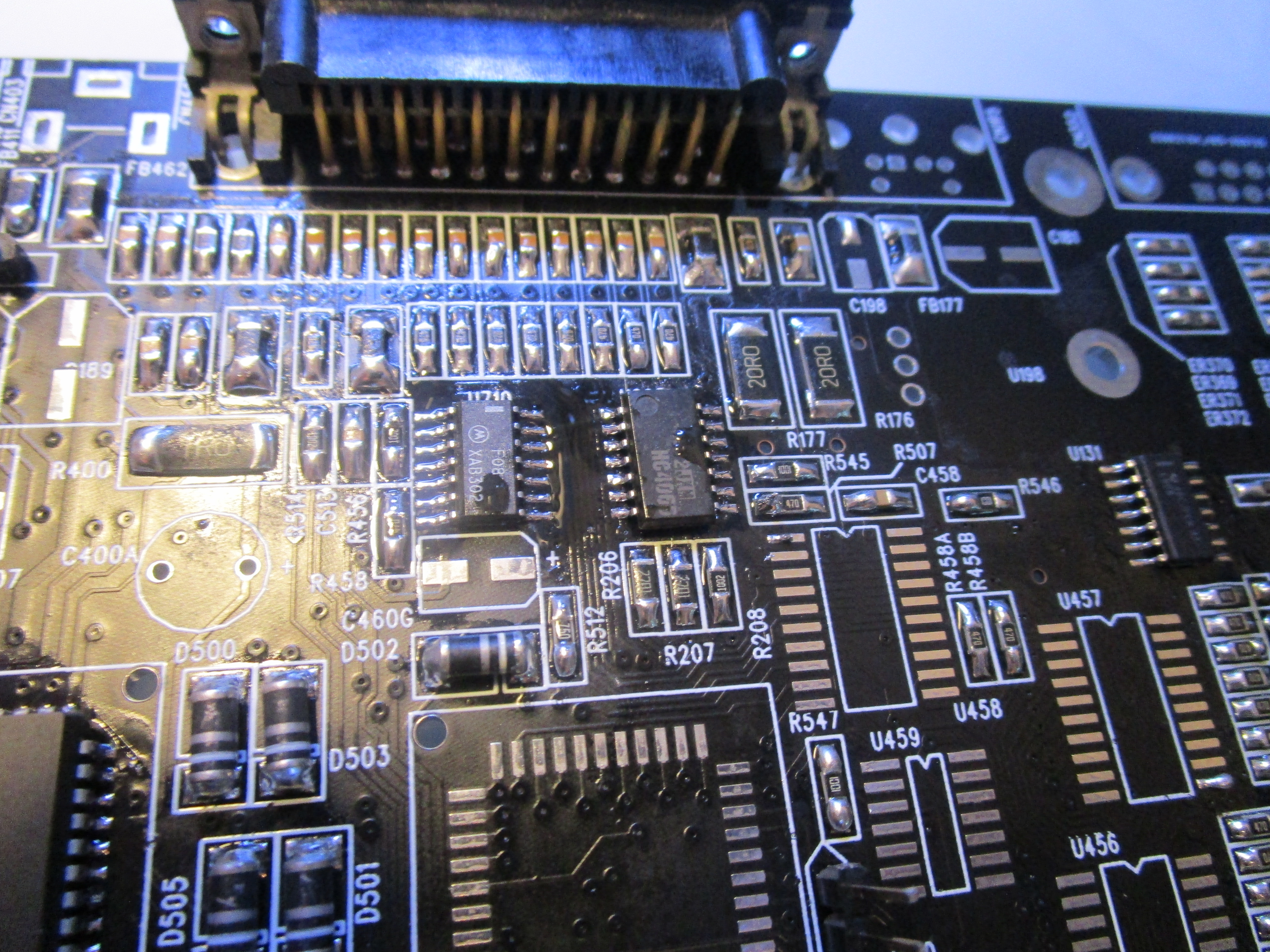
Now to get a display shown:
Add U459 (74F74), U458, U457, U456, U455 (74FCT245), U460 (ADV7120), D507 (LM385-1.2)

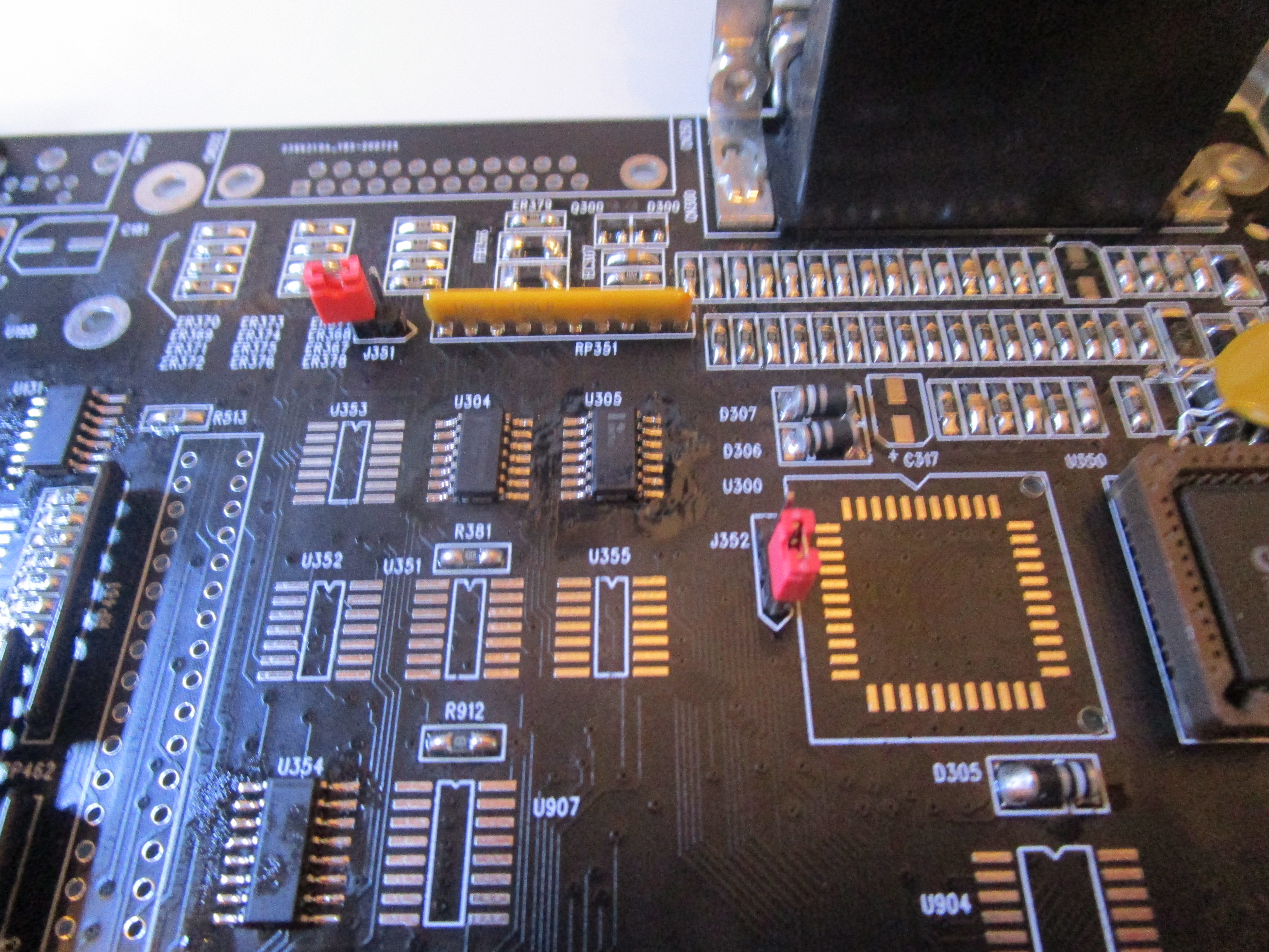
Now time to add the next CIA, Put in U300 (8520)

Now CIA tests will work, also Parallelport.
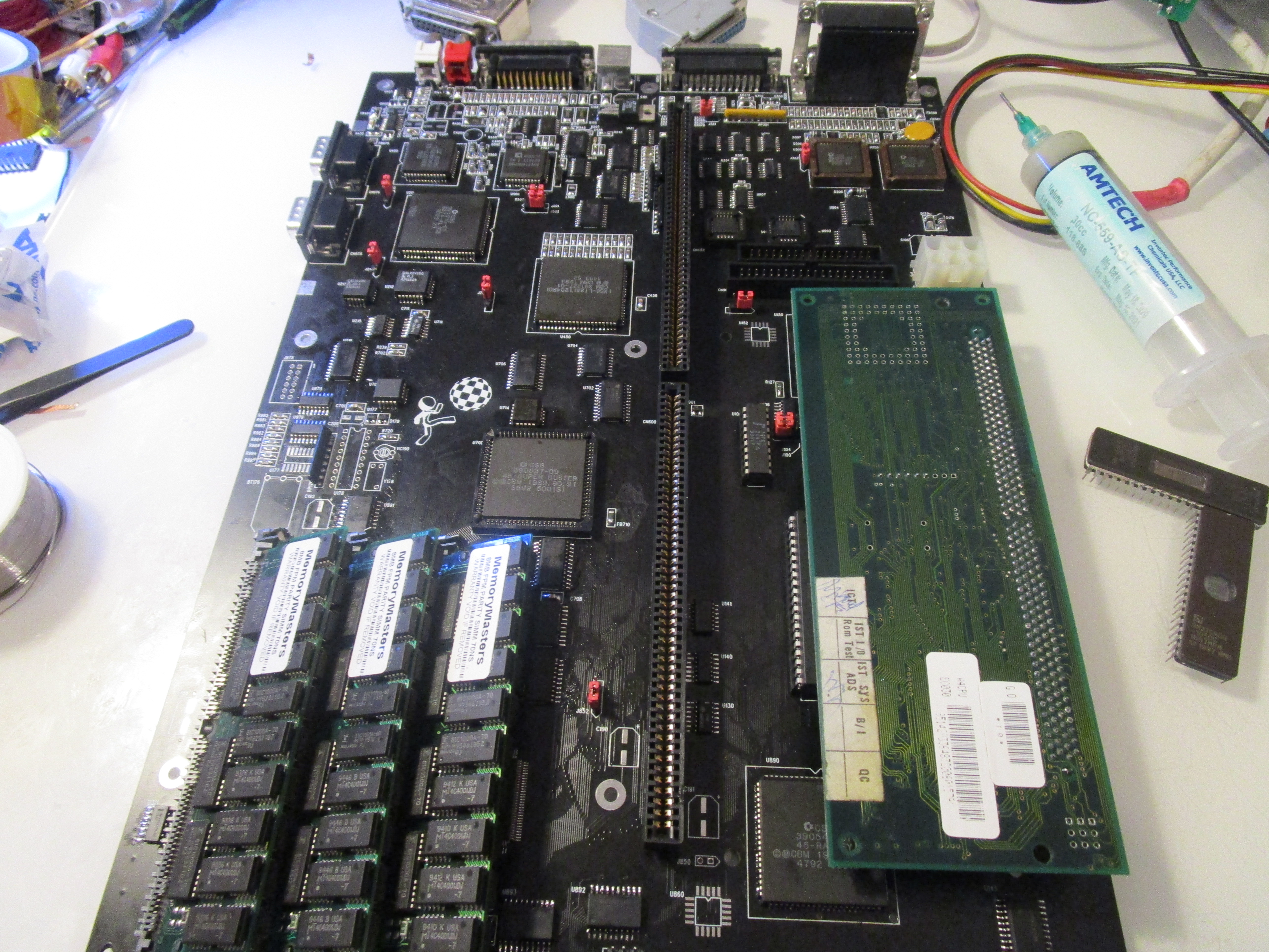
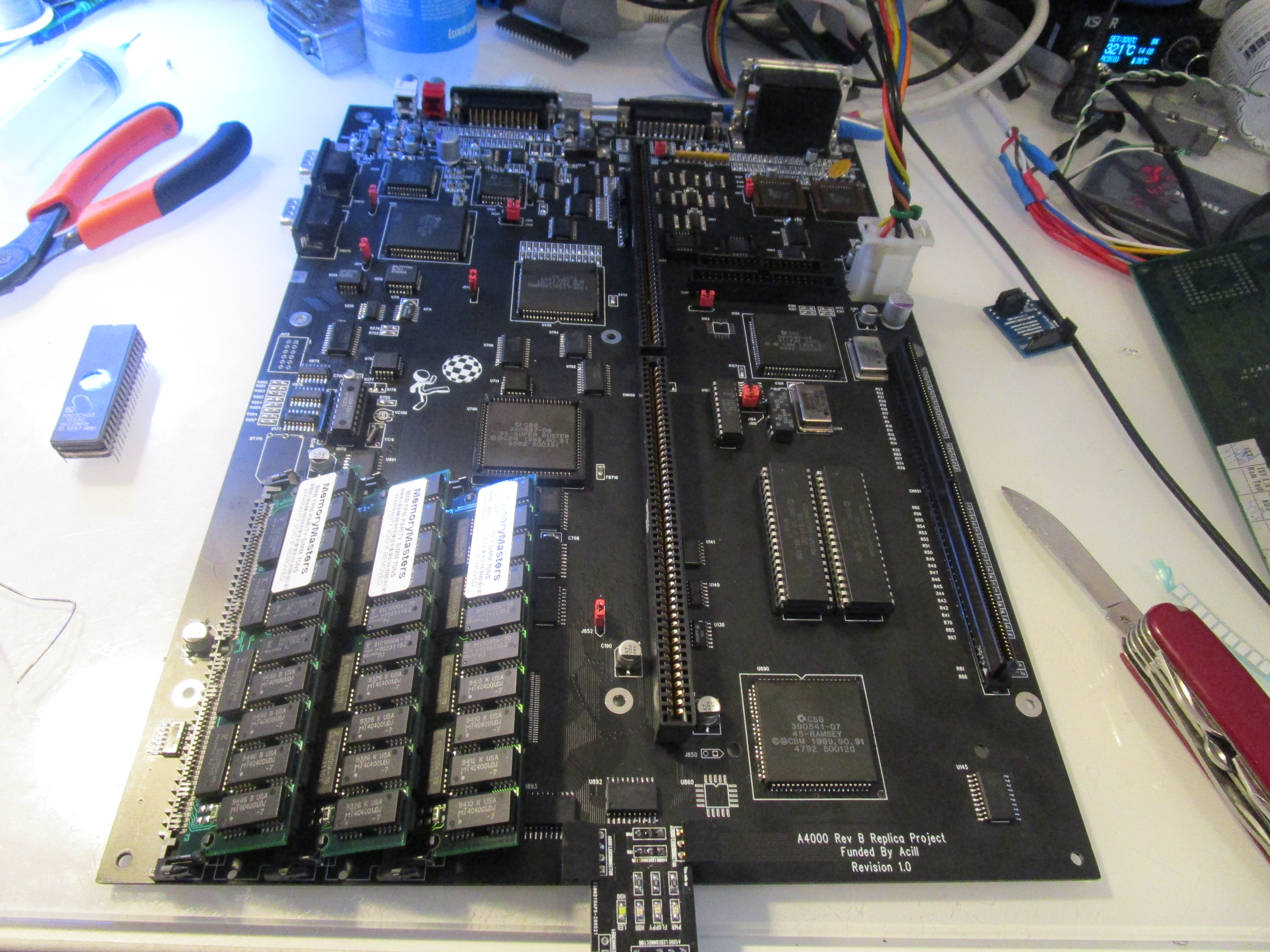
Time for some Fastmem:
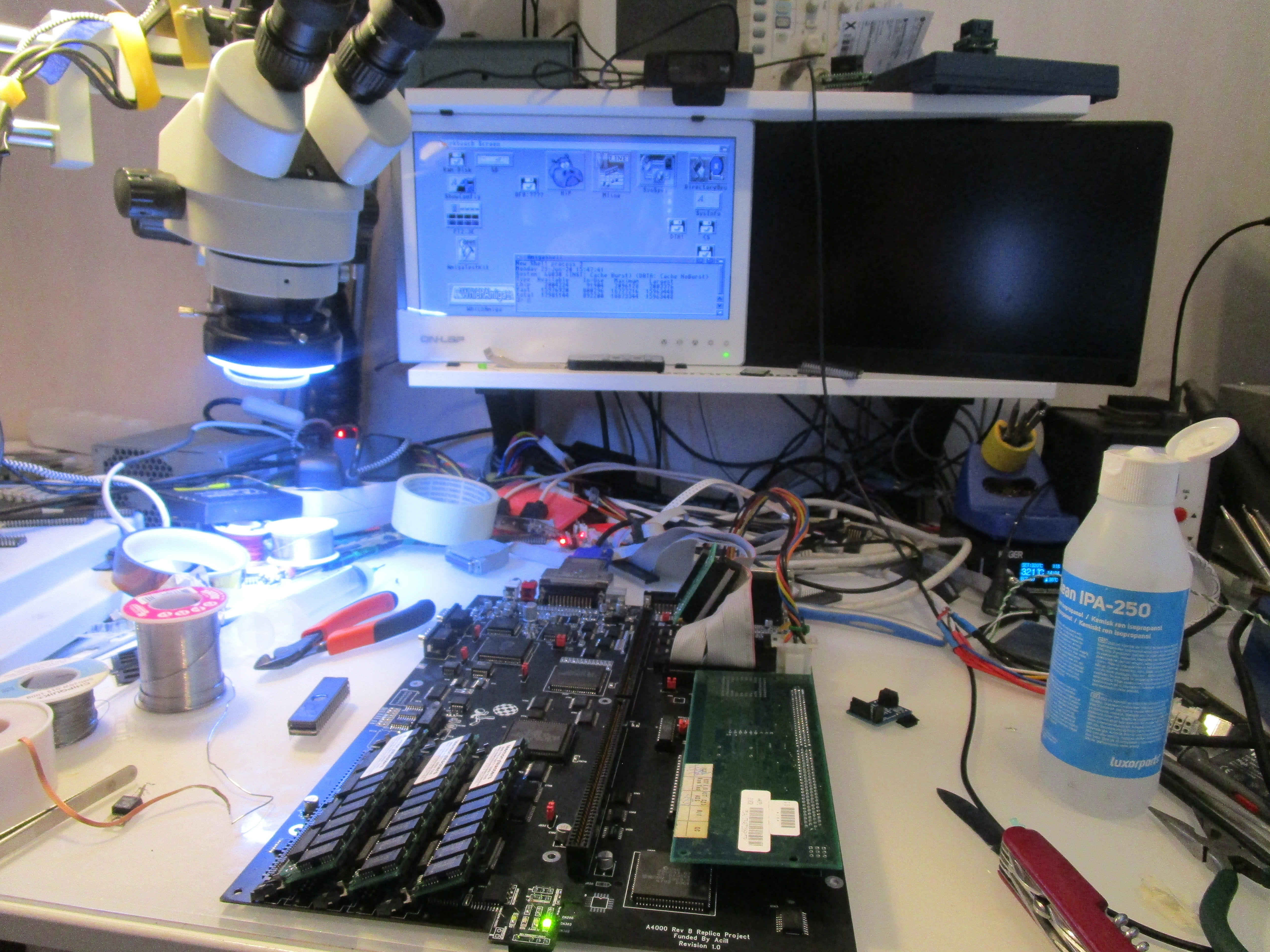
Add U890 (Ramsey), U891, U892, U893, U894 (74F245) and SIMM sockets.
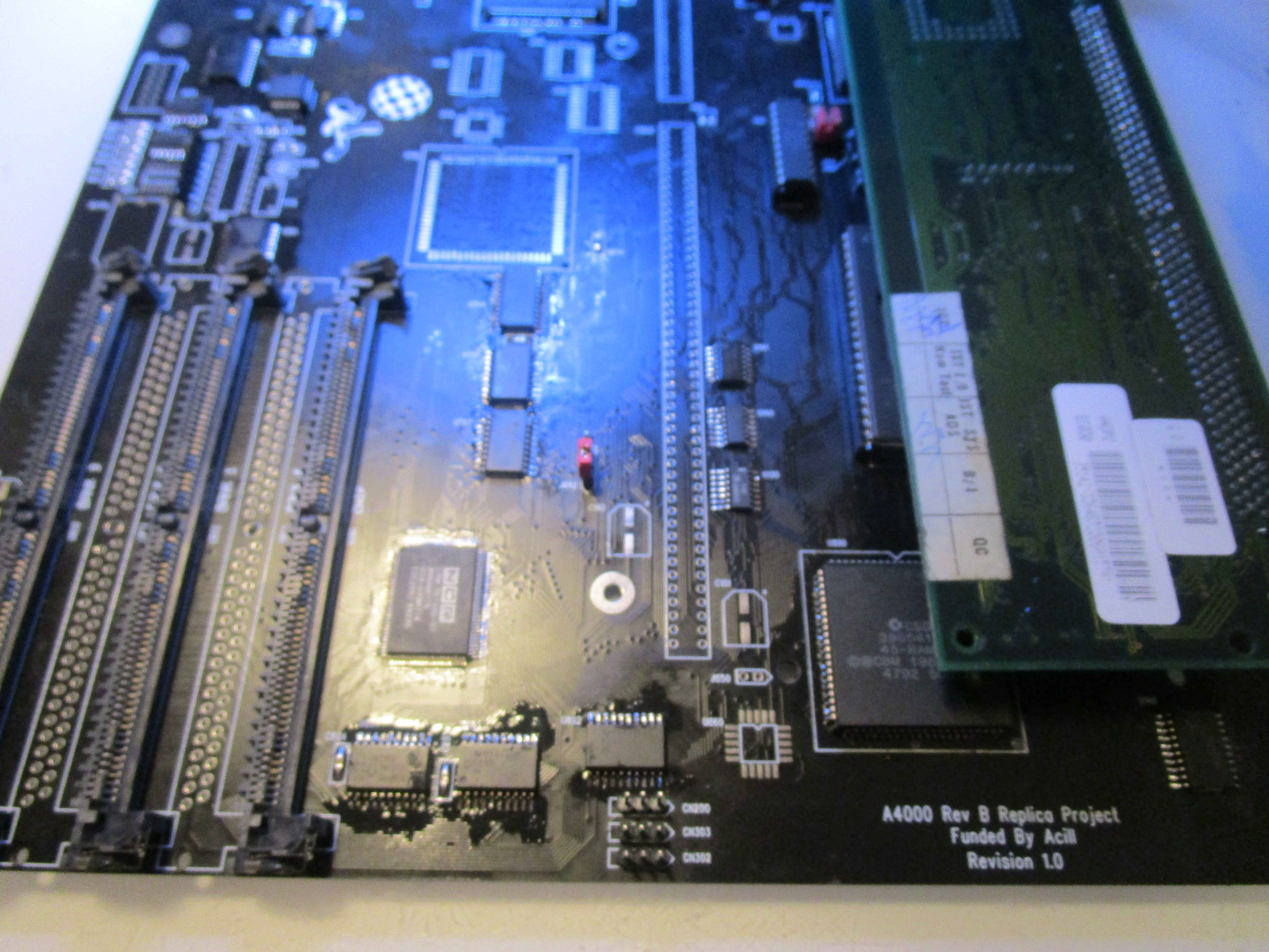
BUT! here you can see something odd I did. instead of putting in all sockets, I take every 2nd. this is due to the undocumented A4000 possability of being able to use 8MB simms instead of 4MB. and as I bought a 100pack of 8MB simms I preffer this. (NO. 16 is still max without hacks!) and as 8MB simms are doublesided. by not adding those not used simms they will fit. if the socket was there 8MB simms will not fit.
it is all about what you want to do. I want to save simmsockets so.. I use 8MB simms:

(and again that 8MB chipmemsocket will still only give 2MB chip, the “extra” 6MB is lost!
Anyway, go on. lets add IDE:
Add U902 (GAL), U907 (74HCT174), U903, U904 (74HC245) and the IDE Connector.
you can remove that KEY pin for many “PC Compatible” IDE cables as it is not in use anyway.
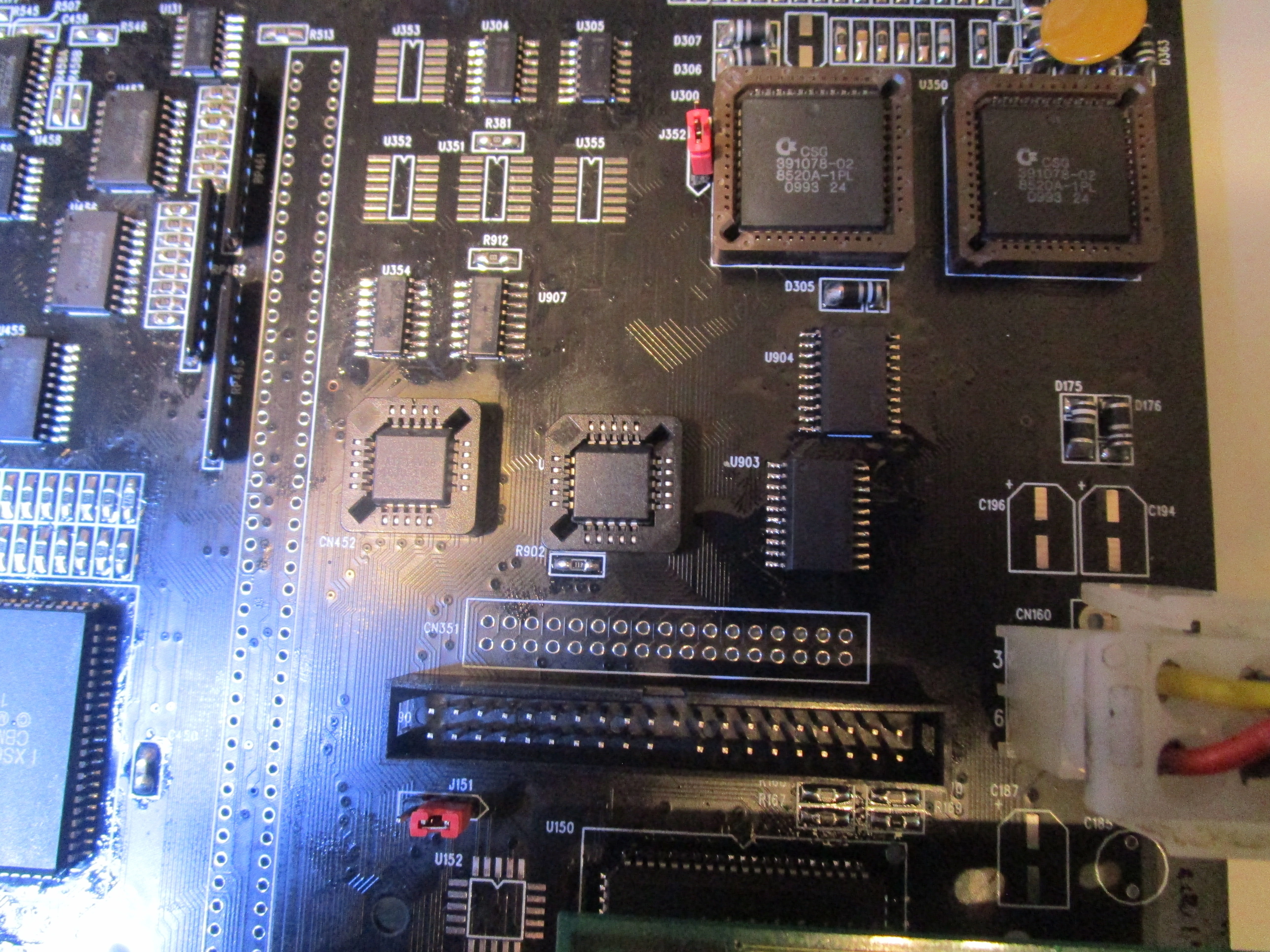
U901 and U902 is GALs needed for IDE. we added U901 first at without it, machine will not always start. and I got it here in sockets as some want to use the PIO2 mode hack for faster IDE. this is a quite ok hack but will sometimes fail, so with sockets you can go back more easy.
again! sockets is a source of issues!
Anyway, next step is FLOPPY:
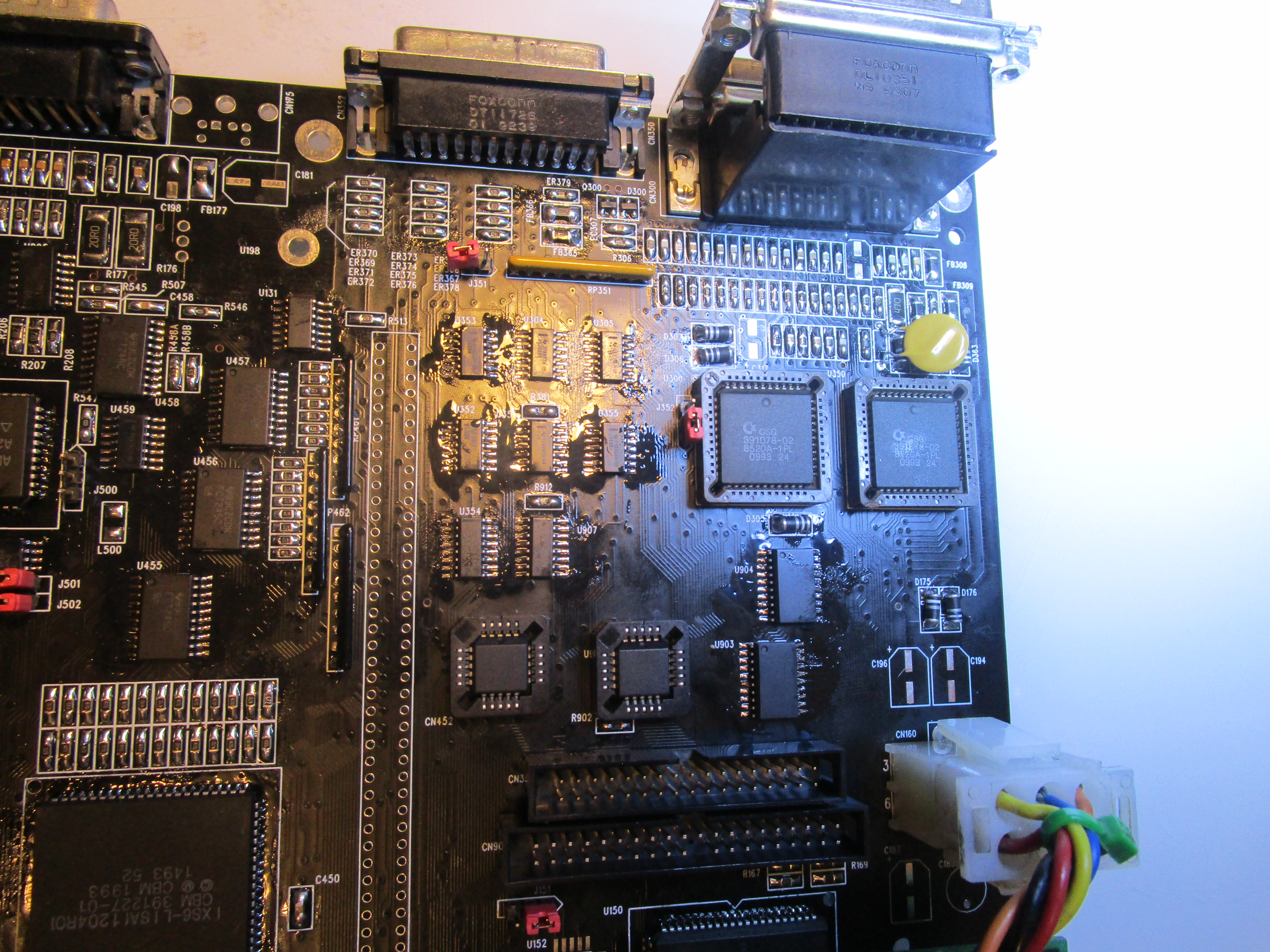
add U353, U355 (74LS125A), U352 (74LS38), U351 (74LS74A), External Floppy Connector, Internal Floppy Connector.
now it is a good time to add the keyboardconnector

for Audio add:
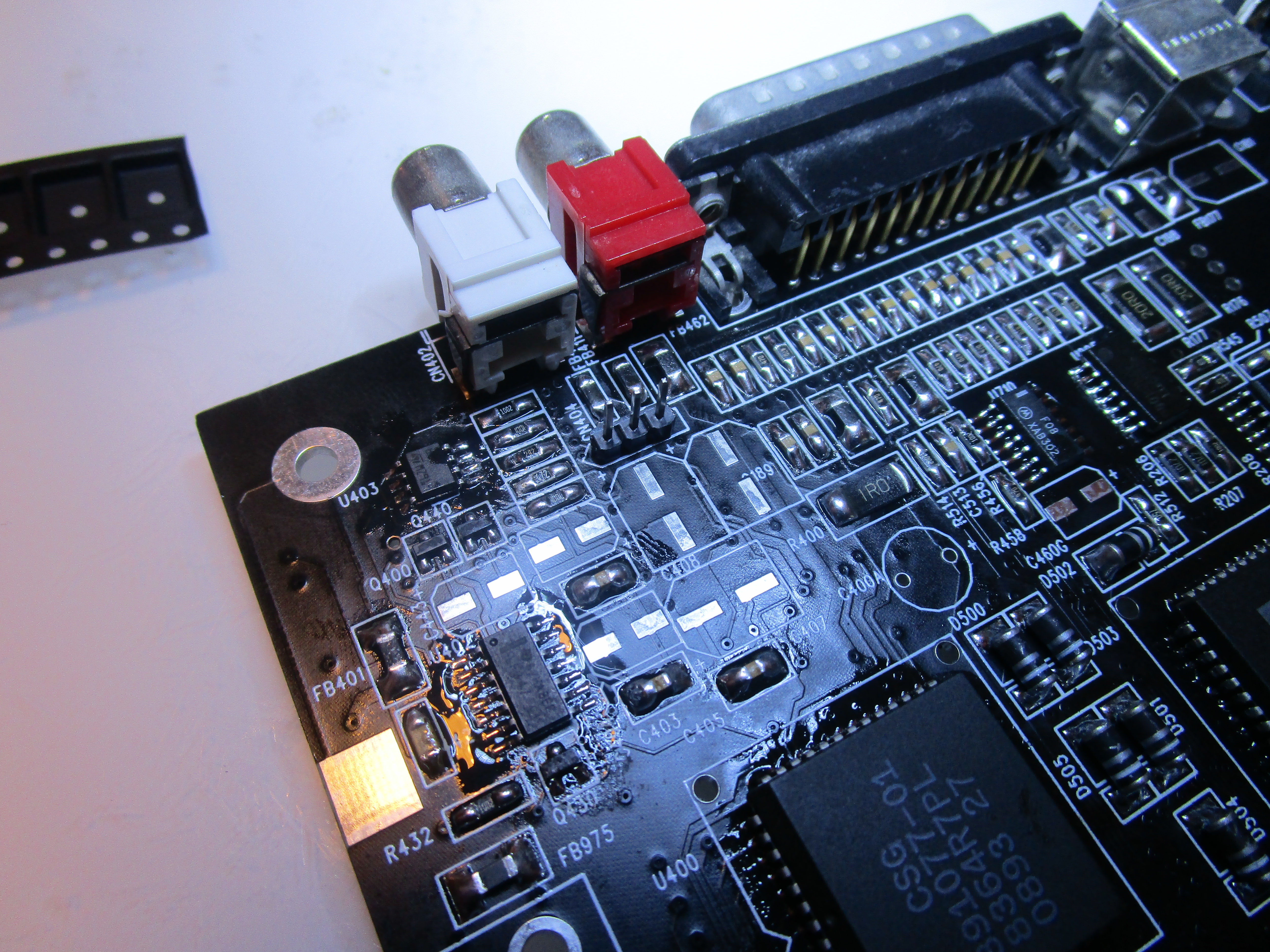
U403 (LM833), U402 (LM347) and RCA Connectors
however we haven’t added the audiocaps so there will be no audio yet. I wait with those as I want to ultrasonic clean the board and it is not recomended to have electrolytes on when doing this.
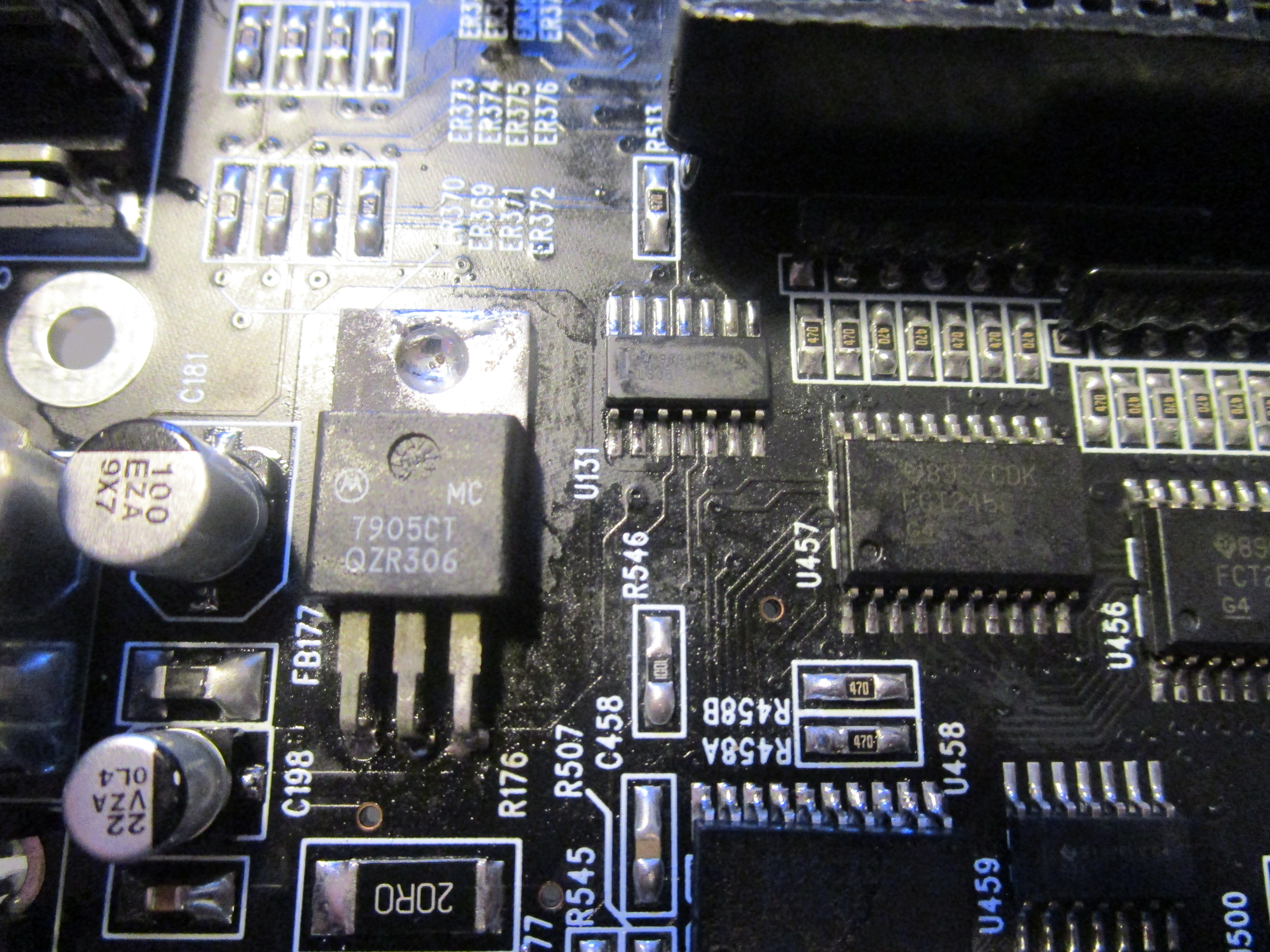
Add game and mouseports
and add U198 the Voltregulator that creates the -5V to the board
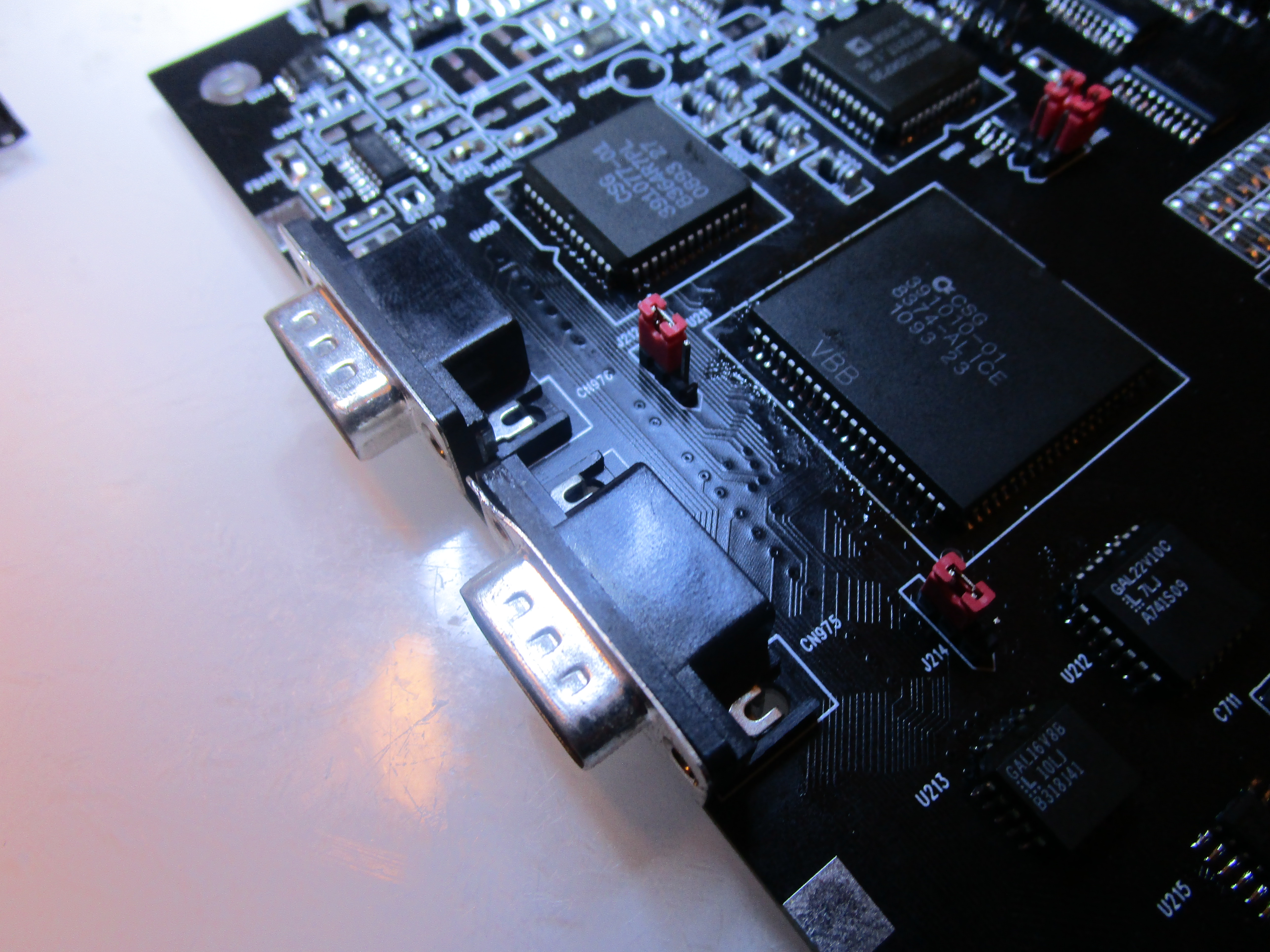
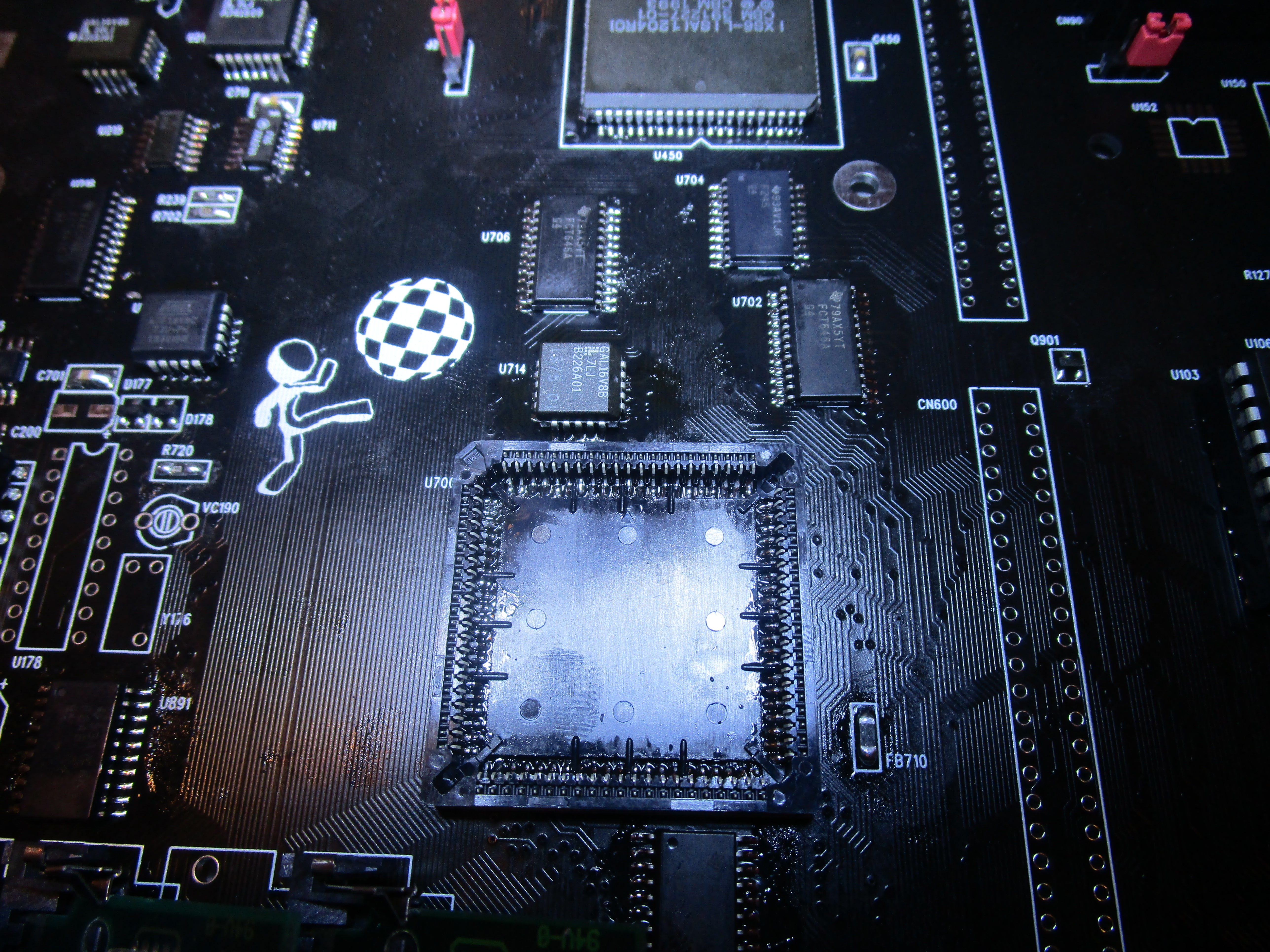
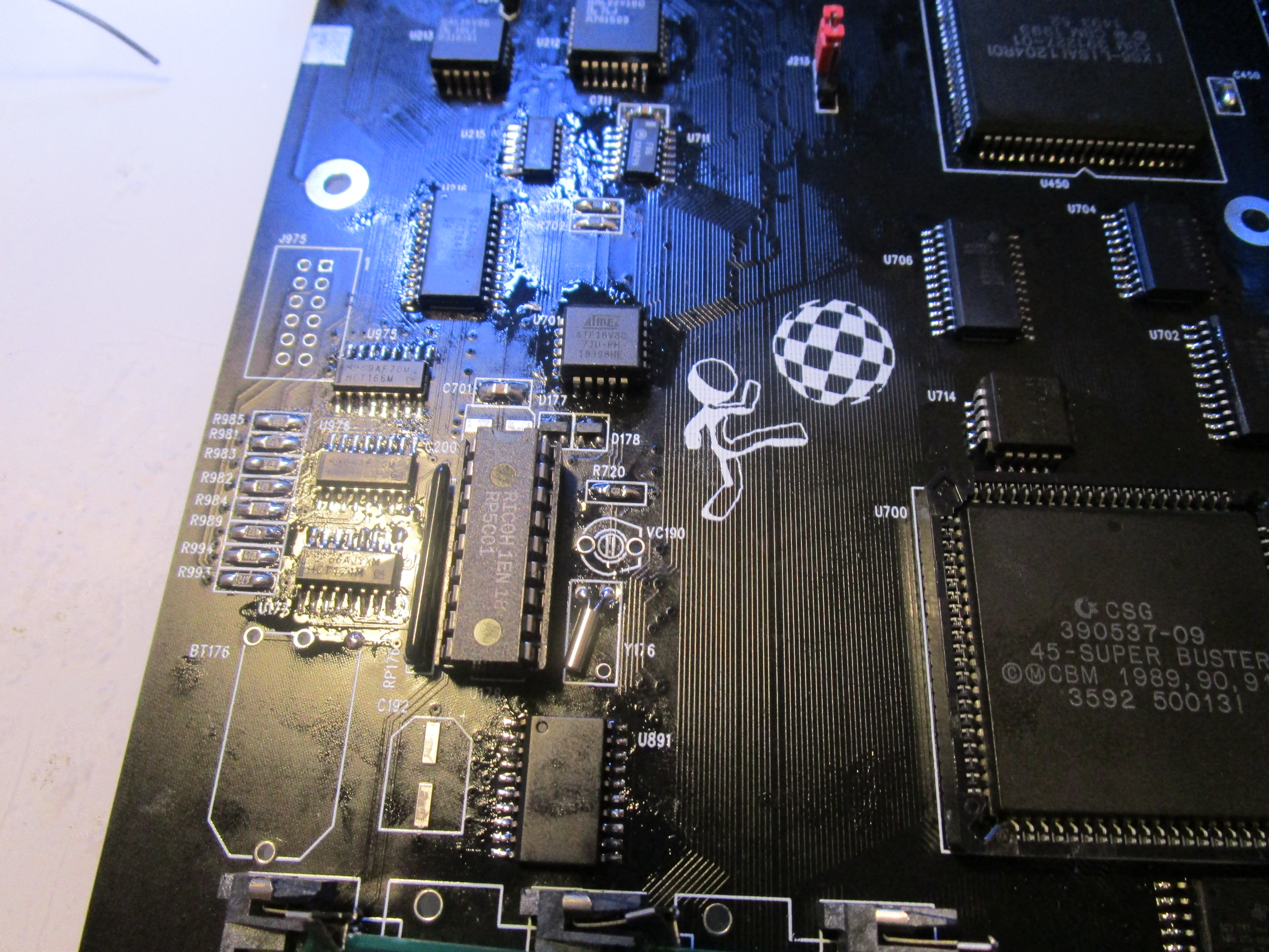
Time to add stuff for zorroslots:
add U795, U702 (74FCT646), U704 (74F245), U714 (GAL), U700 (Buster) and the DB slot connector
and finally add for RTC:
Add U177 (74HCT174) and put the RTC chip in a socket, and add the Y176 (32768Hz) oscillator. I wait with the trim-cap as ulatrasonic.
technically you can skip this part as well I preffer to sync my clock with NTP on network. but hey add it.
now I do a ultrasonic clean
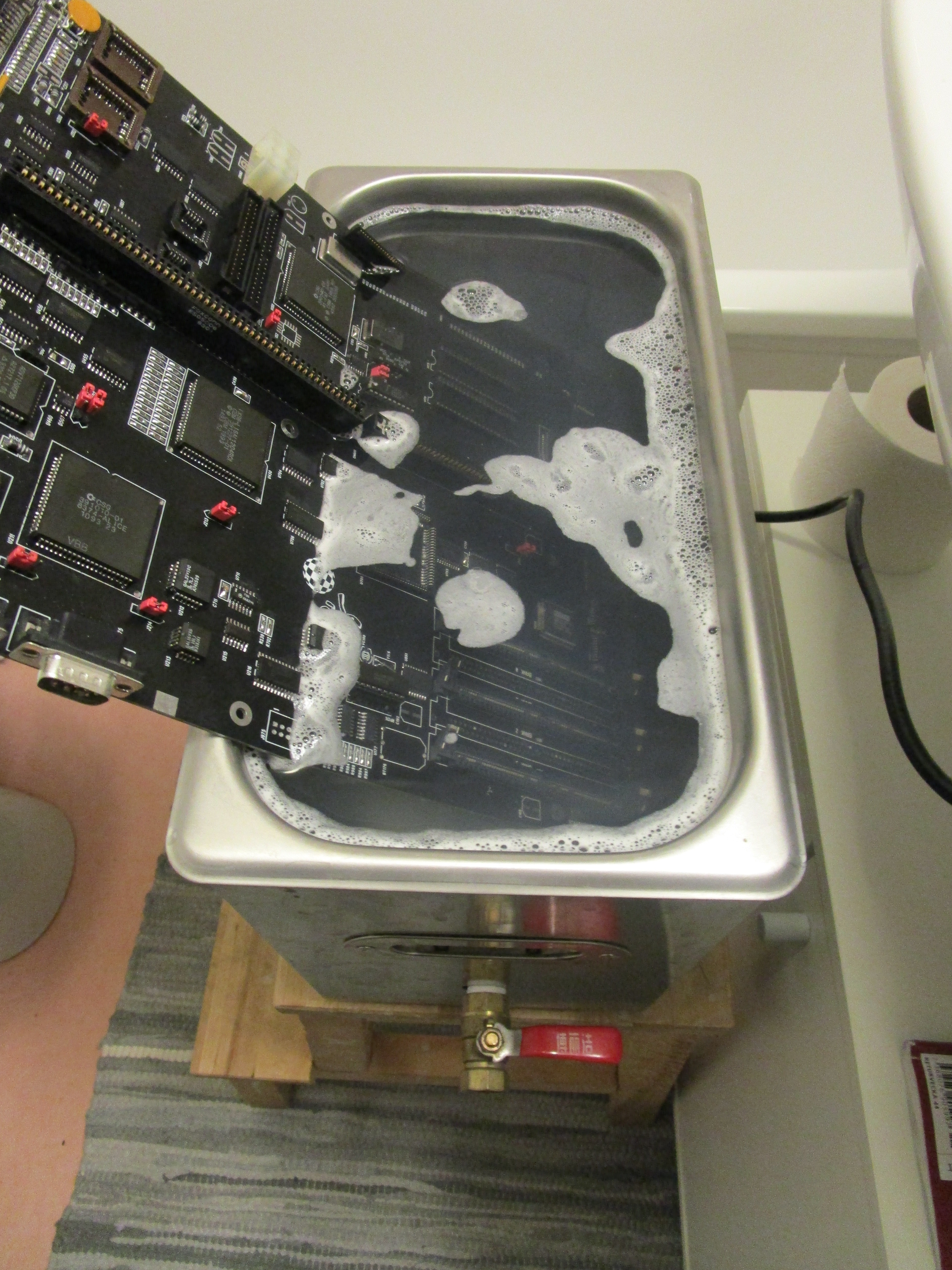
I need to do this in 2 passes. this is to clean flux from the board, you can do it with isopropanol and babywipes or so. there are many ways of cleaning up flux. even dishwasher without chemicals works. but you will need to make sure it is DRY after. and with components removed from sockets.
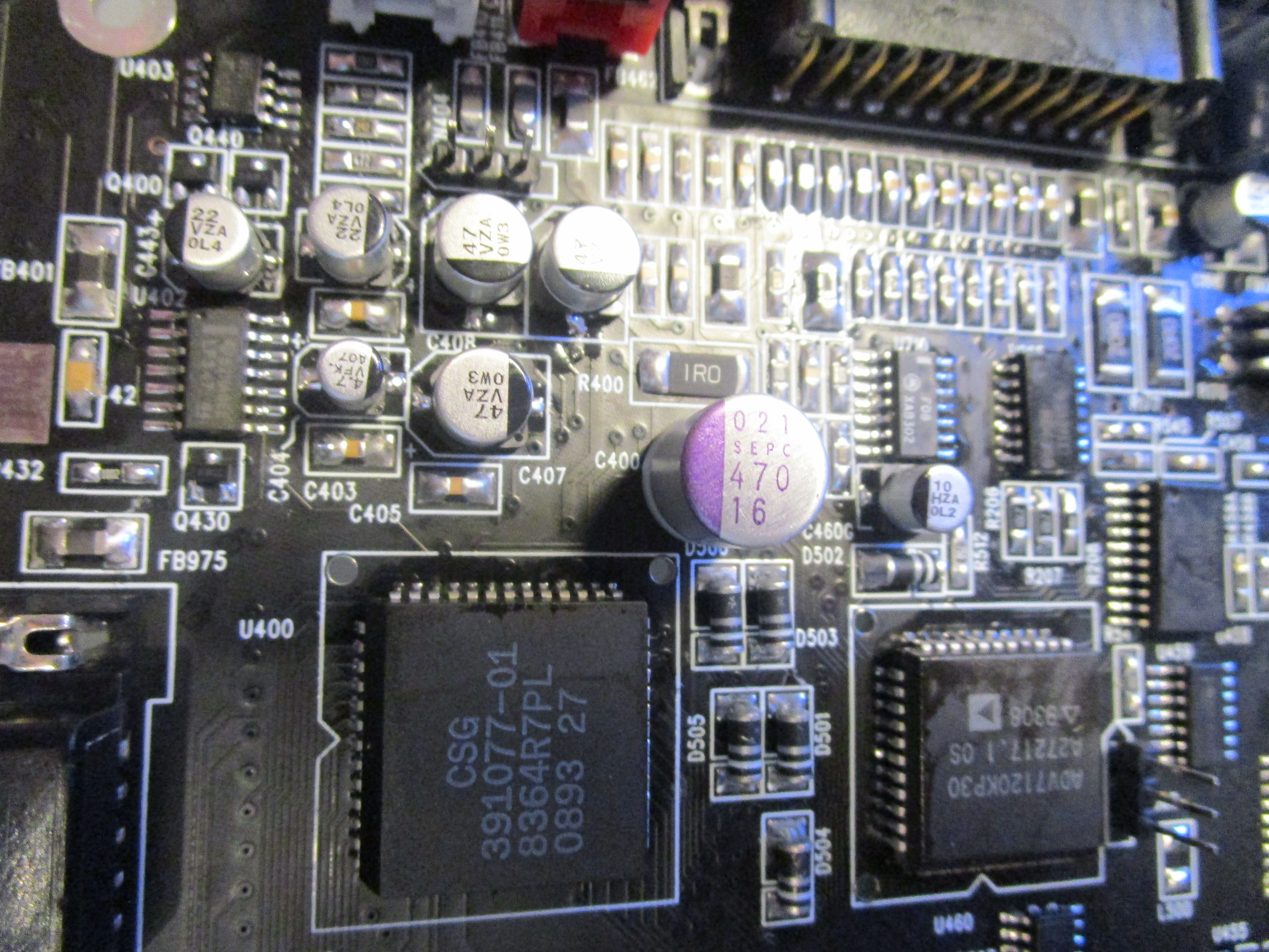
Anyway. after ultrasonic and drying up (isopropanolbath etc) time for the electrlytic caps.
here some want to use Ceramic or tantals.. STOP! they behave different, even if they can be used in some parts you shold not use for audio etc.
modern hybrid aluminum caps will not leak. so stop changing caps that behaves totally different. a booting machine is not a sign of working caps (as you can see, machine is booting here with caps not even installed)
and a note about audiocaps: 2 caps have wrong orientation on A4000: C443 and C433 so I install them “wrong”)
(I have had comments about this not being true.. but no links to info about prof so.. anyway just measure yourself and see!)
and NO. you do NOT need nonpolarized caps here it will never swing negative.
so add all caps, also add the RTC trimcap (I will do a post about trimming RTC cap someday, generally a value of 22pF is ok enough)
and battery/coincell solution.
AND…
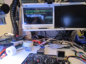
you are DONE!
Yet another Amiga booting up! ENJOY!
Hi JOHN, I have a question, are these memories 2 x 32 bit or 2 x 36 bit ?
greetings
Zenek
32 bit. you can use 36. the rest is ignored
Hi John.
Great write-up as usual, very thorough and informative. Any chance of you doing one of tbtorro’s A4000T motherboards next?
“no”
as I simply do not have one 🙂