Well.. “A few days” suddenly was WAY more.. out of reasons I cannot even remember things never happend. I built the board but never documented it.
HOWEVER. As I build a new board I now documented THIS build.
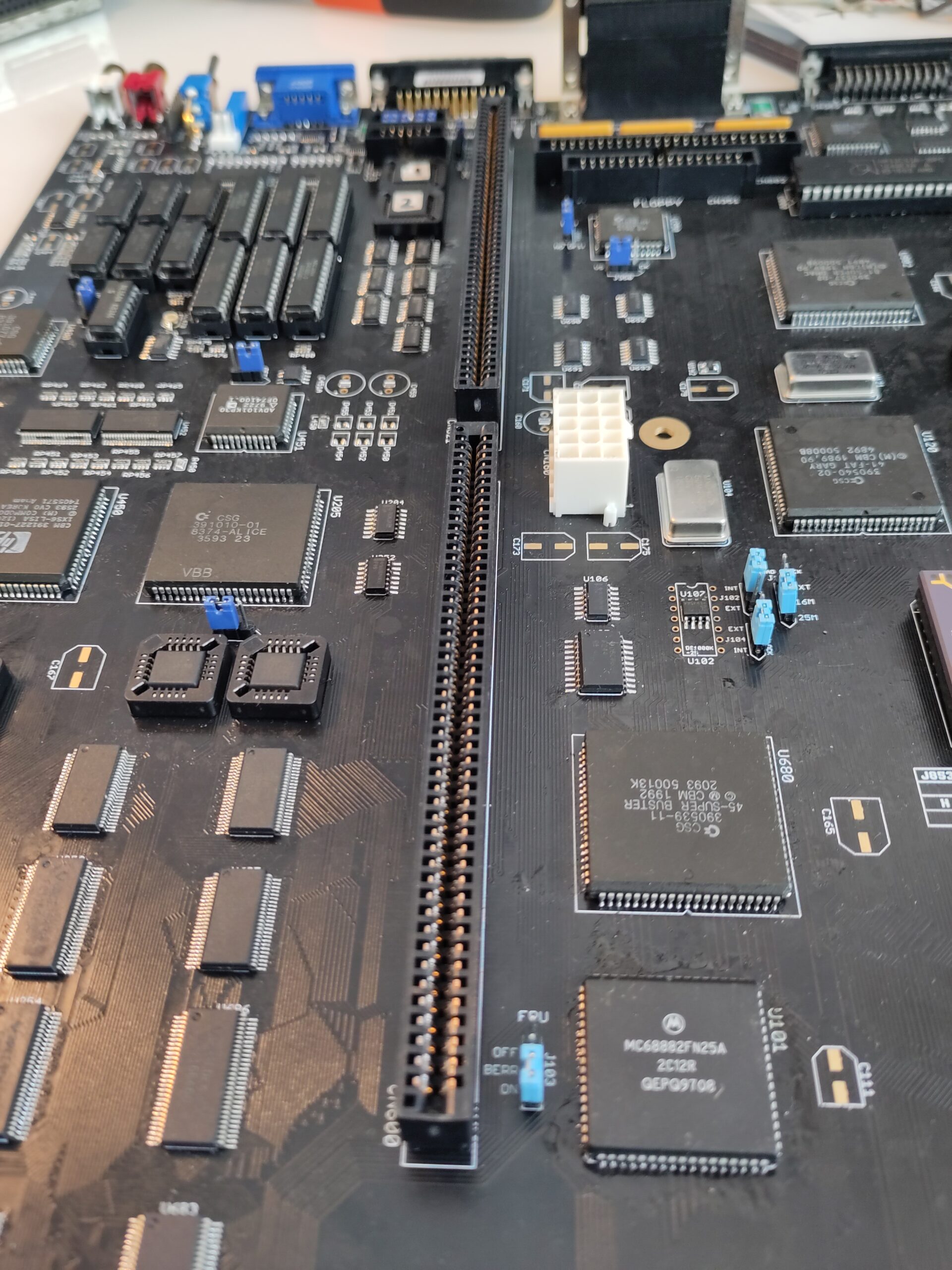
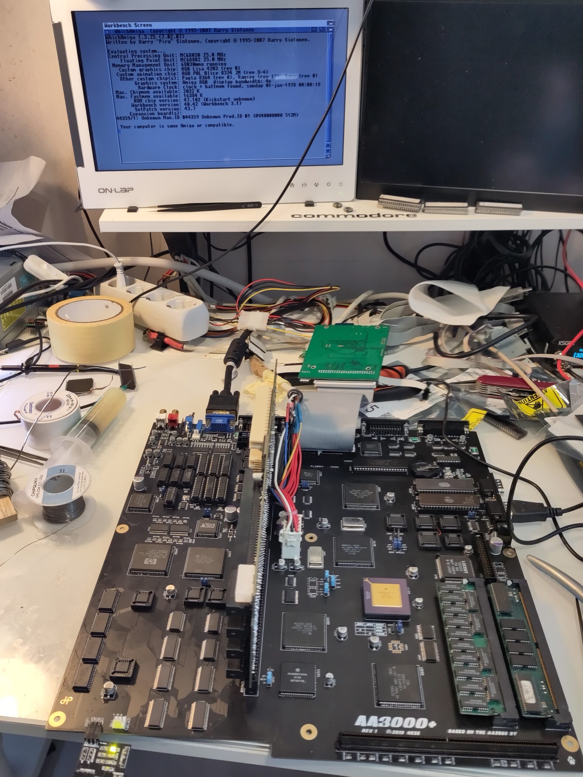
so here is the new board I am working from:
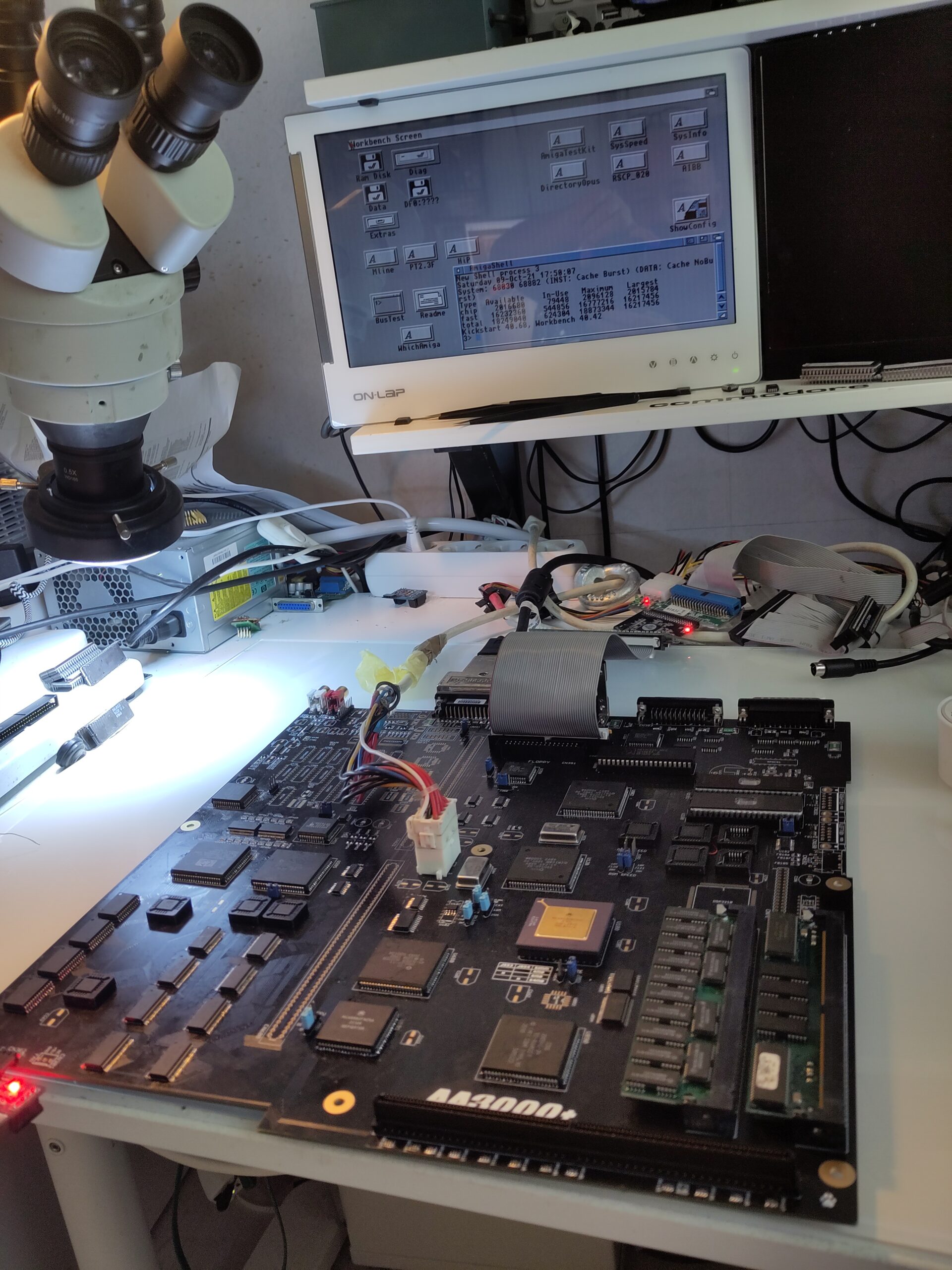

As you can see. pretty much same state except that I skipped sockets for the chipset here. (sockets are a reason for issues)
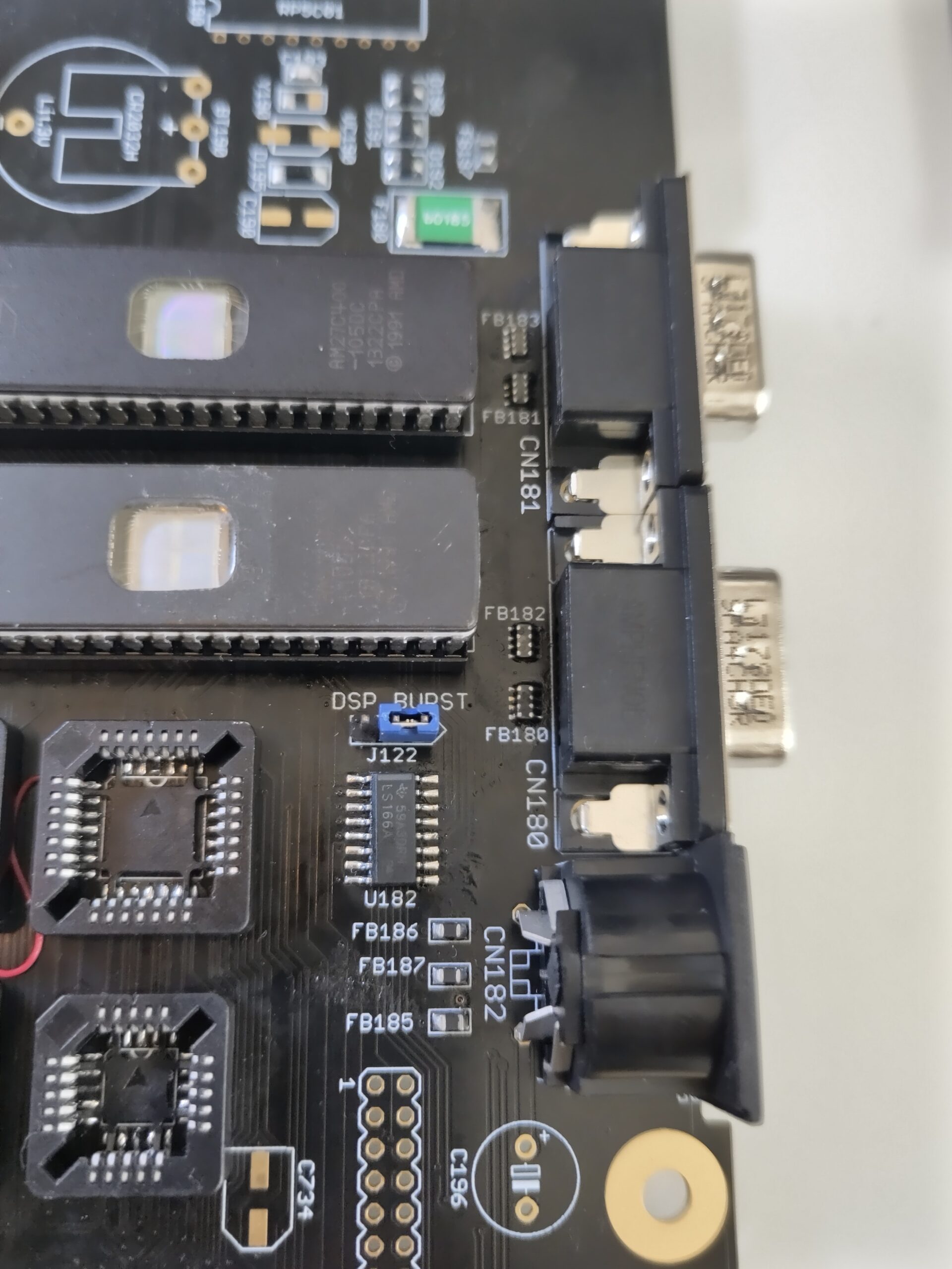
Anyway time to go to the next part of this and that is simply to add the 2 9Pin DSub and the keyboard connector. A hint is to make sure you have no shorts on the resistor/capacitornets now. as it is WAY more easy to fix that with connectors off. 🙂
status with connectors on:
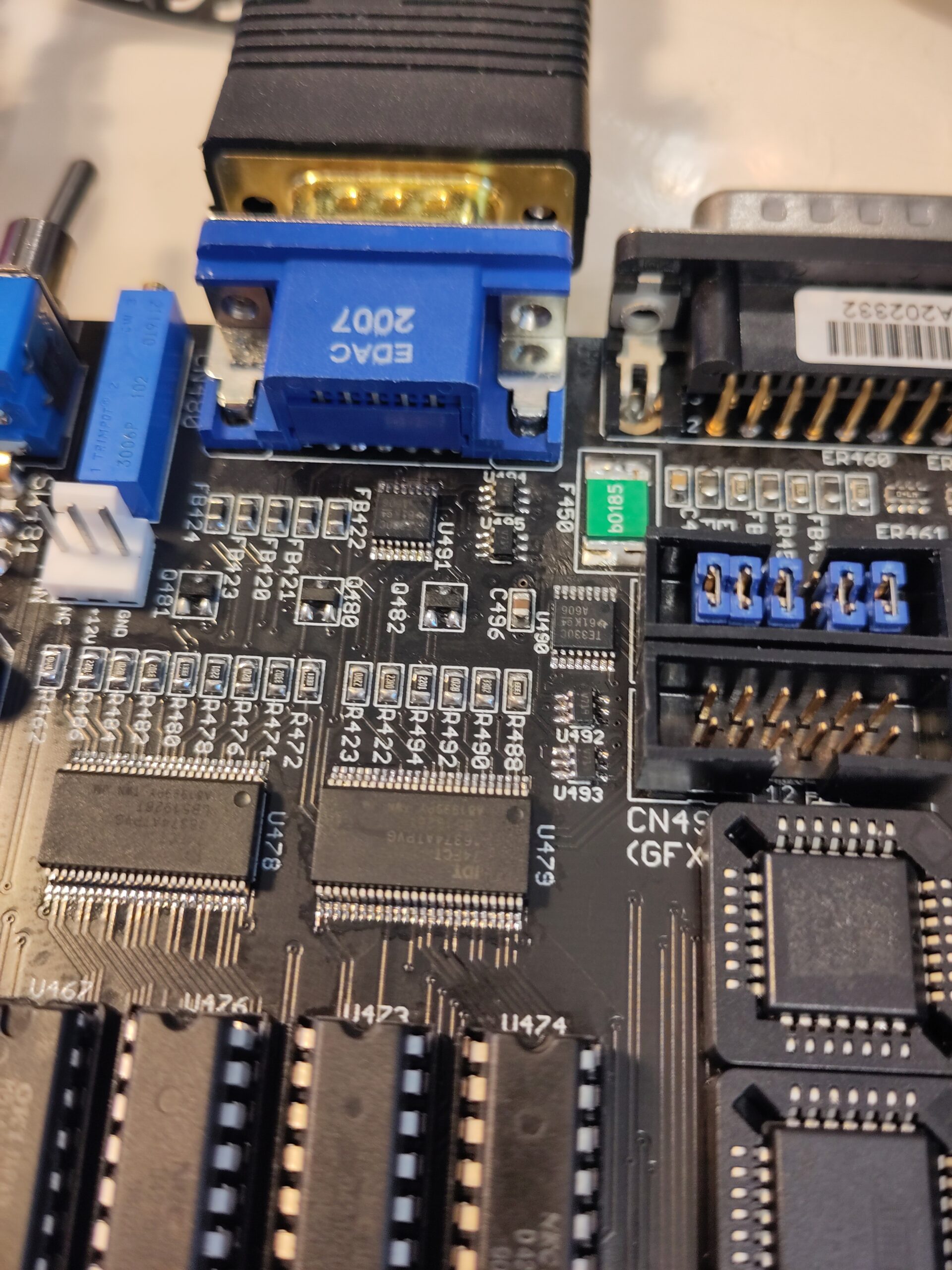
Now with that done. time to get the Flickerfixer to work.
Program the 2 22V10 GALs and solder them on U460 and U461.
TS5V330 at U490, U491
STG719STR at U492, U493, U494 and U495
74FCT16374 at U478, Y479
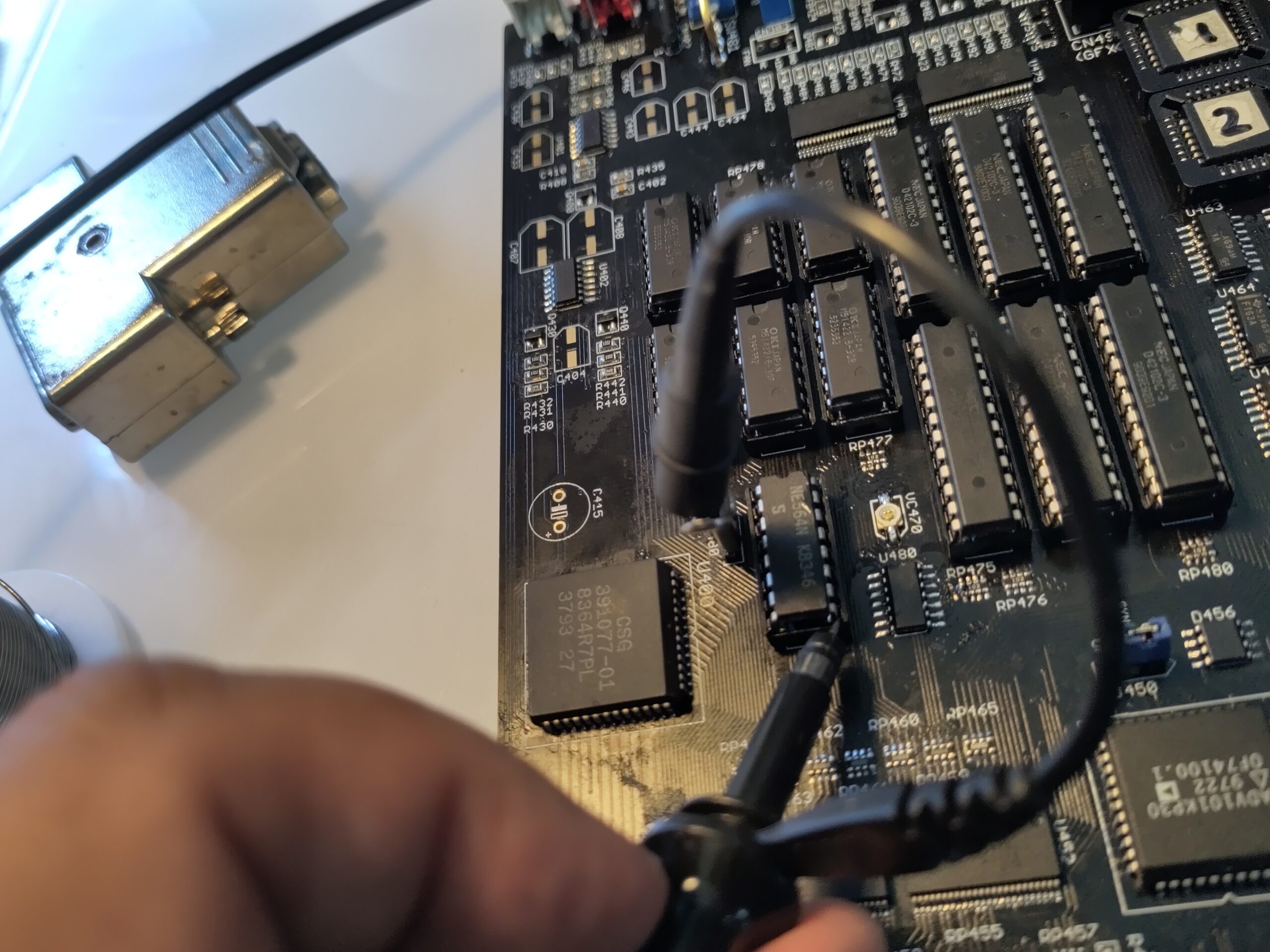
D42102 at U472, U473, U474, U475, U476 and U477.
MSM514221 at U466, U467, U468, U469, U470 and U471
NE564 at U482
VC470 (2-10pF)
74HC04 at U480
74F163 at U462, U463, U464 and U483
74F175 at U465
74F02 at U481
74F74 at U454
VGA Connector at CN480
1K Trim at VR470
Switch at SW481
Connectors at CN490 and CN491.
NOTE on CN490 you will need to put some jumpers like this:
It is a part of the built in VGA Switch. with this it works. it will be up to you to find documentation about this. (I MIGHT update this build at a later stage about this)
now you will need to trim the VC470 to get a picture.. you can use a oscilloscope to help.
I put the GND on the leftover pin at the jumper and probe pin 9.
for me it started with:
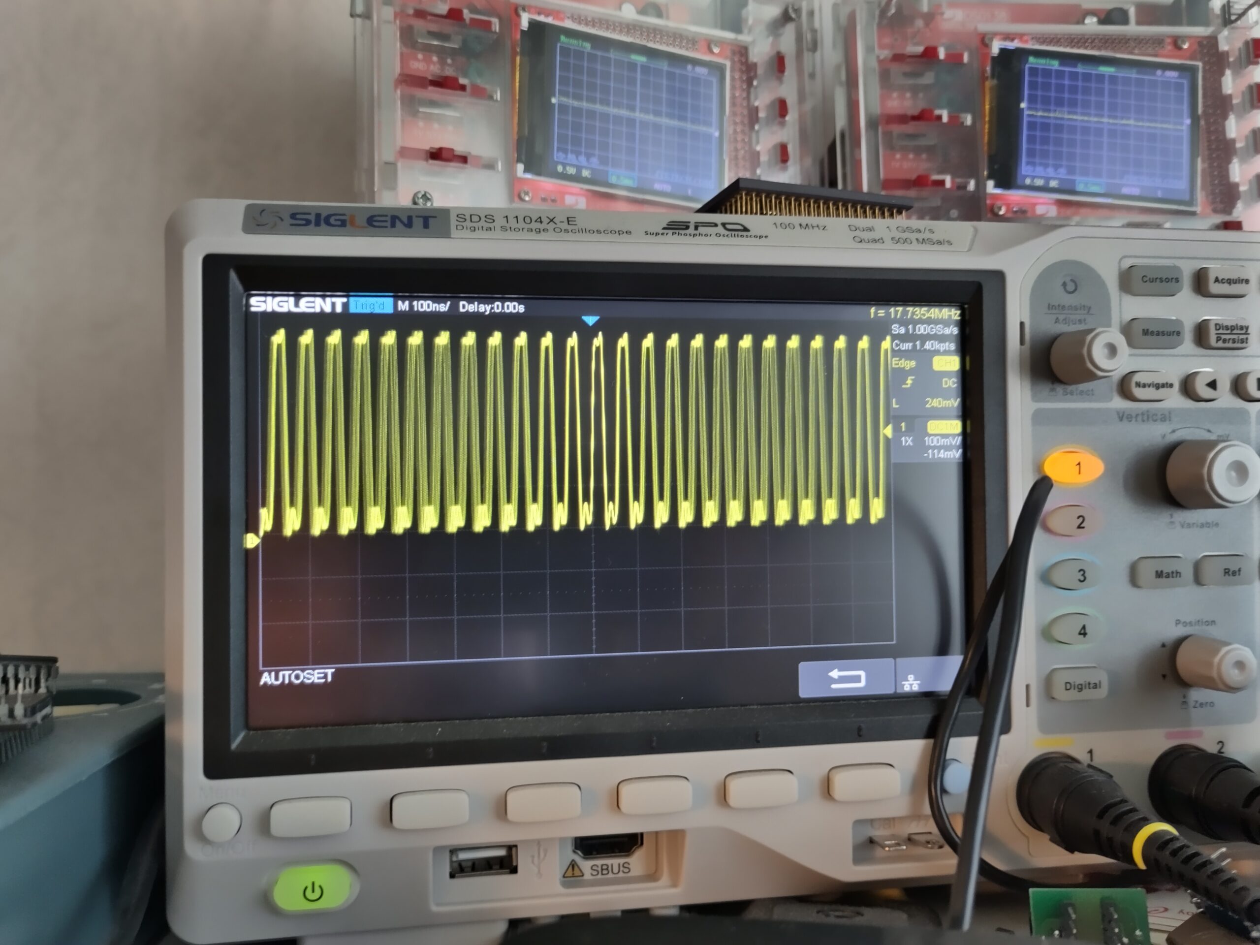
Picture doesn’t show that good. but wave is not even.. so turn the VC470 with a isolated screwdriver until the signal gets to a nice even signal:
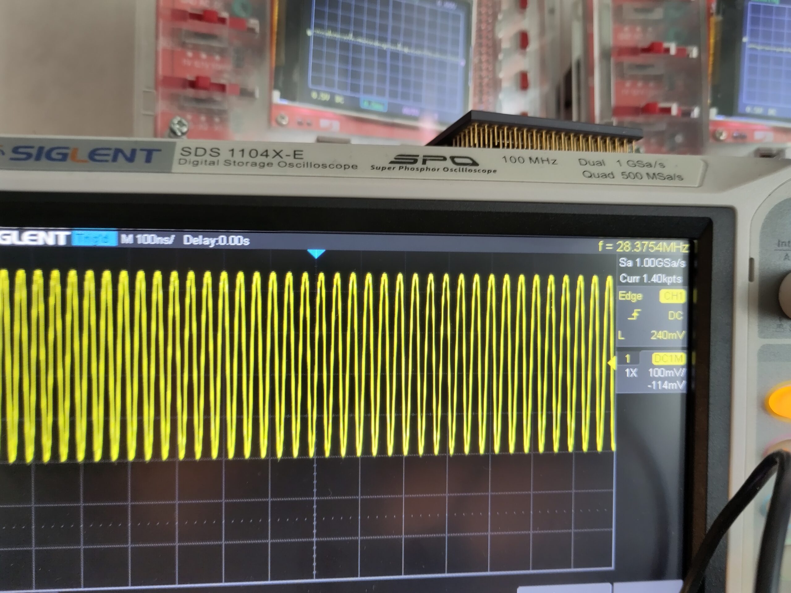
And you should also get something on the screen. you do not need an oscilloscope but it is more easy when you have it.
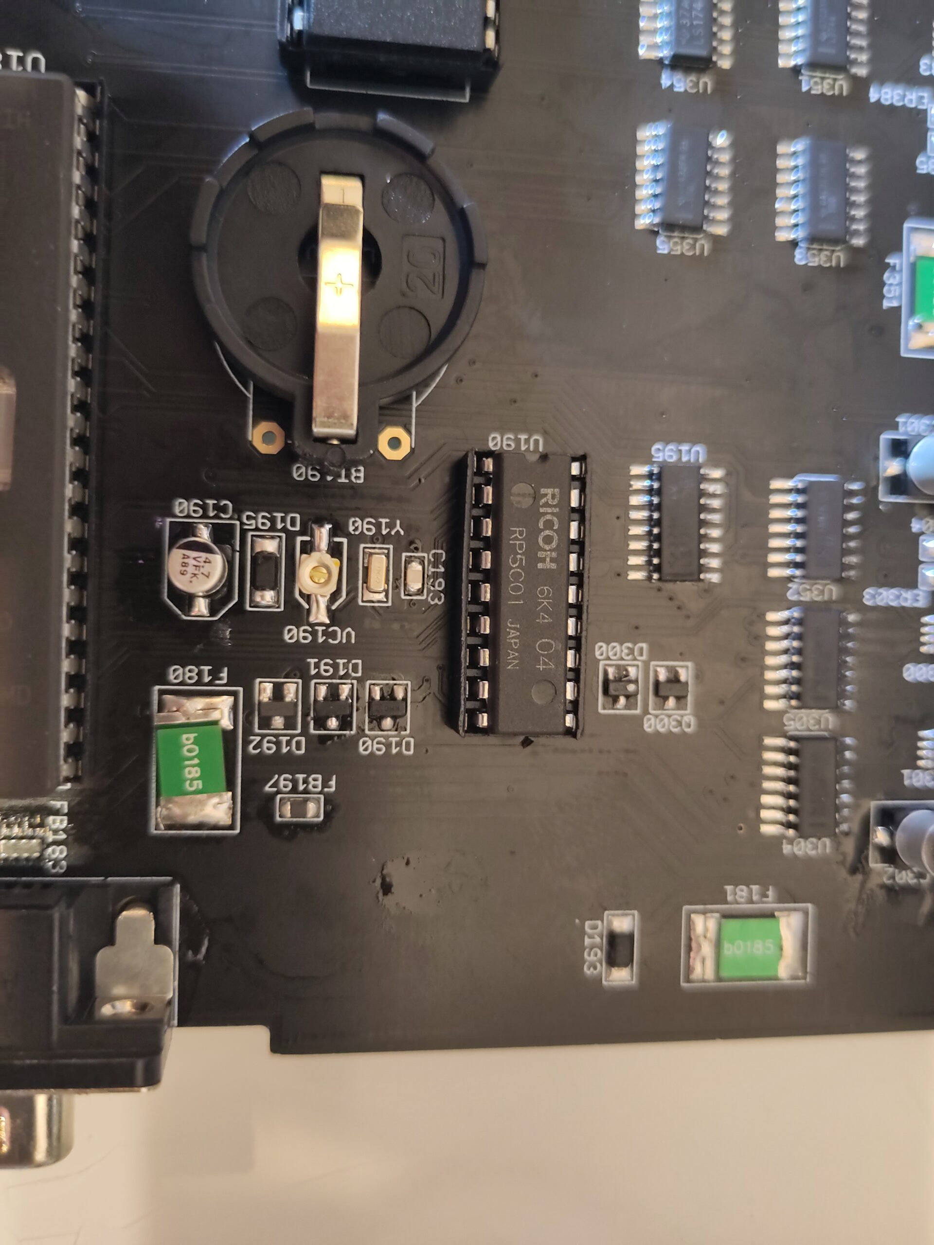
Now it is time for the RTC.
Solder in oscillator at Y490, Batteryholder (this was kinda tricky as the holes did not fit for me. some bending of pins and I managed it.
Put in VC190, and the RTC Chip.
NOTE Depending of battery you want to use:
NiCad: Install R192 (bottom side), don’t install D192
Lithium: Install D192, don’t install R192
as I will use CR2032 coincell battery, I installed D192 and made sure R192 was not there.
Now just solder in the FAN Connector and the Zorro Connectors:
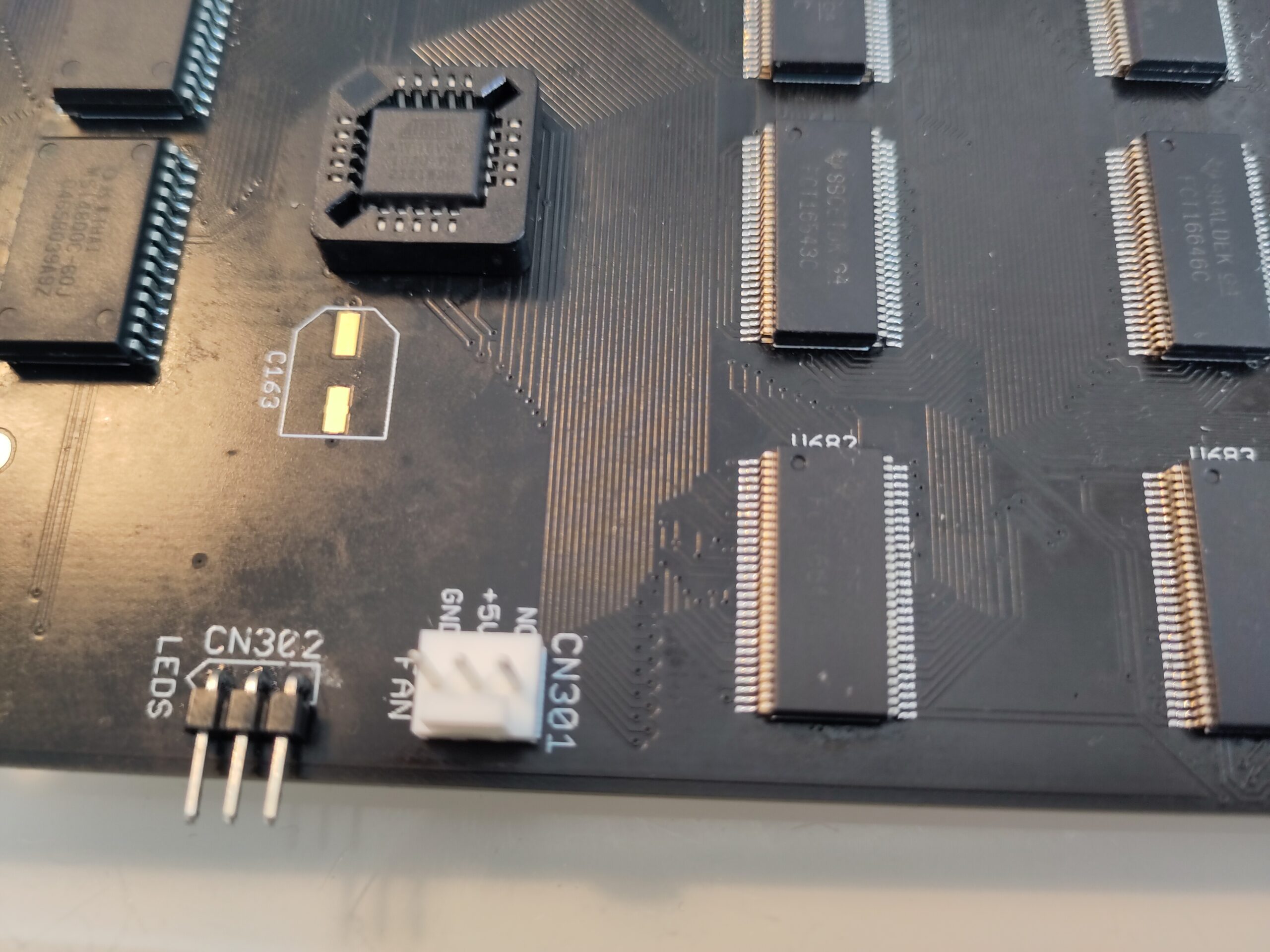
on some parts the zorroconnector pins are quite long so you MIGHT need to trim them on the other side (cutting off extra long pins)
IF you do not want to use the DSP. you are actually done now. just put on the electrolytes and the machine is done.
However .. time for the DSP:
This is not a 100% done project. I woud recoment looking at:
https://github.com/realA10001986/AmigaDSP3210
and:
https://www.a1k.org/forum/index.php?threads/76673/
as this is just the TL;DR version of it 🙂
Add Delayline at U702 or U703 depending on your Chip.
You need to change the GAL Codes and on the link above there are new JED files so program U122, U124 and U701 from that archive and U123 from the original AA3000+ archive.
I used 5ns GALs for all.
Solder in the DSP.
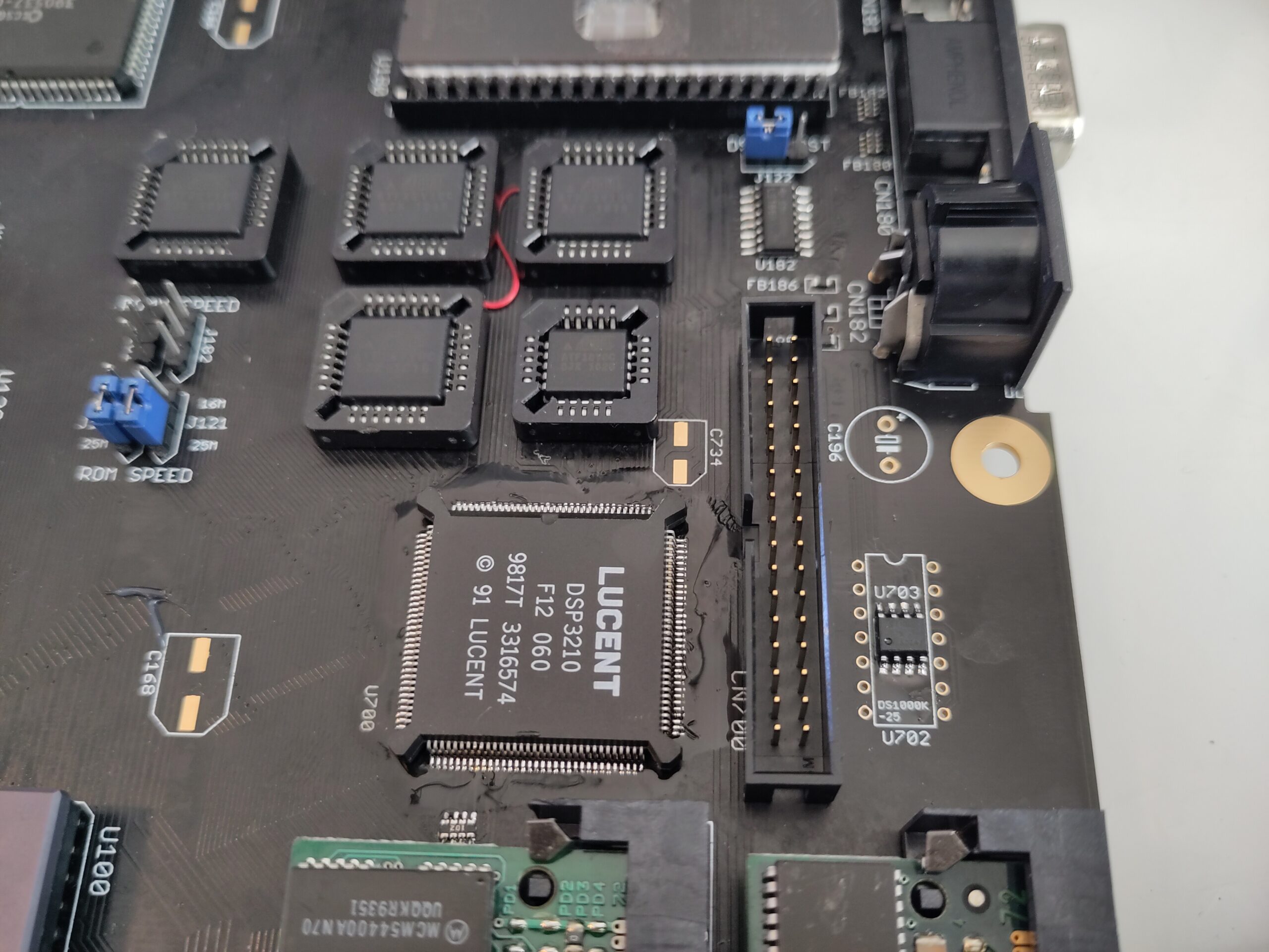
You MIGHT want to wait with the connector until you tested the DSP.
Test the DSP with software in the archive:
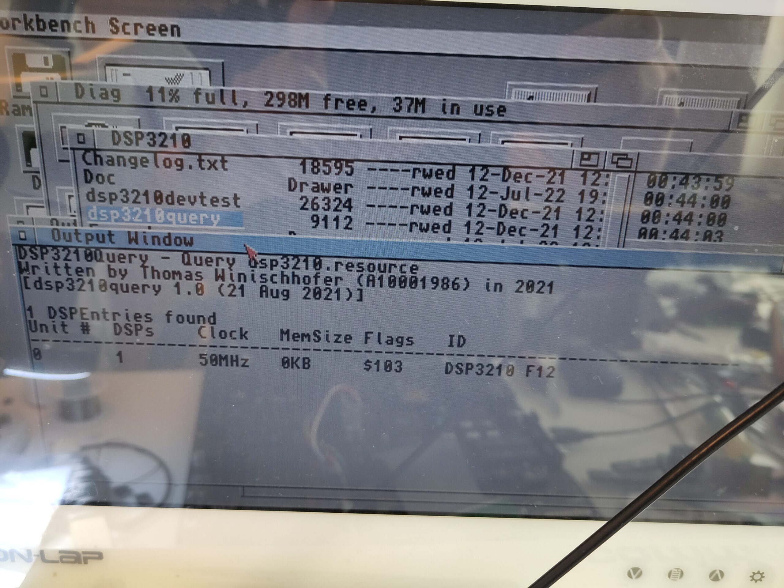
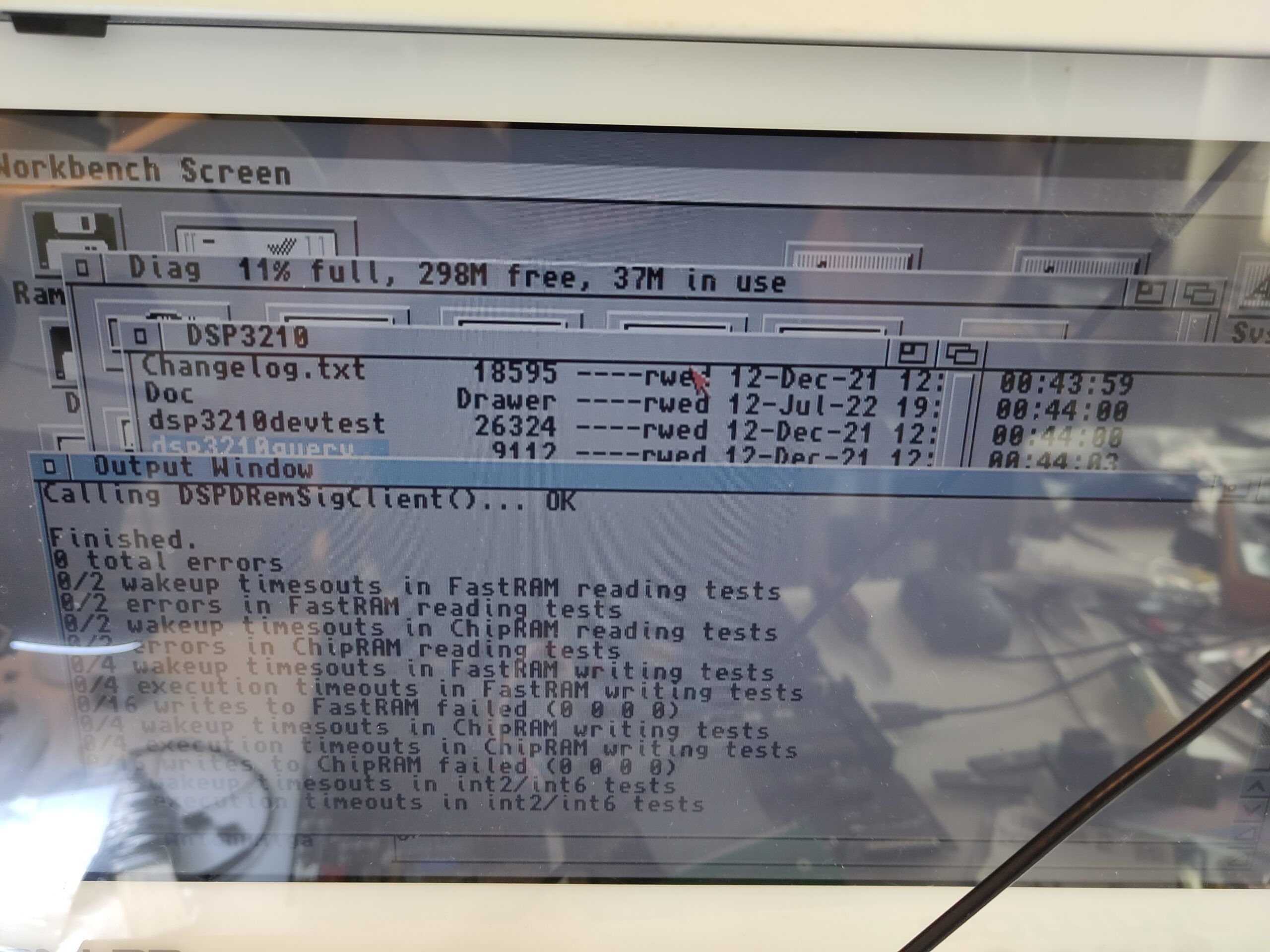
And you are DONE.
Solder in all electrolytes and you are ready to go. (And picturequality would be better aswell)
Picture shows with DB on. Next post will be how to build the DB!
Hi Chucky, An excellent guide.
I am a little stuck on my build at the moment.
DiagROM has an issue with ChipRAM as it is detected but crashes DiagROM when trying to use it. If I pull U202 to disable ChipRAM, then FastRAM is detected instead and DiagROM boots to serial mode only.
I guess I need to work out what is causing the ChipRAM issues. I have a spare set of ChipRAM ICs so I guess I could swap them out first.
Best Wishes
Andy
Update: It was just a dry joint on one of the ChipRAM resistor packs — phew!