So next step is to try to get rid of cables and adapters of the outside the machine.
As my machine often is actually placed BELOW my desk I am not able to use the Amiga keyboard (that finally WILL be in the machine aswell) I got a Lyra2 keyboard adapter, letting me use a PS/2 type of keyboard on the machine. It also works fine with my KVM switch (allowing me to use keyboard/monitor/mouse (KVM=KeyboardVideoMouse ) on all my machines.)
Well the Lyra adapter comes with a plate for towers, I do not want to go tower.
Also I have a Micromys V4 to be able to use a PS/2 style mouse on my Amiga (with wheelsupport)
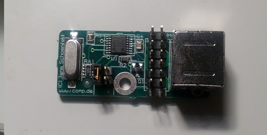
This adapter is also a external thing. I did not want this. So I got a USB->PS/2 adapter:
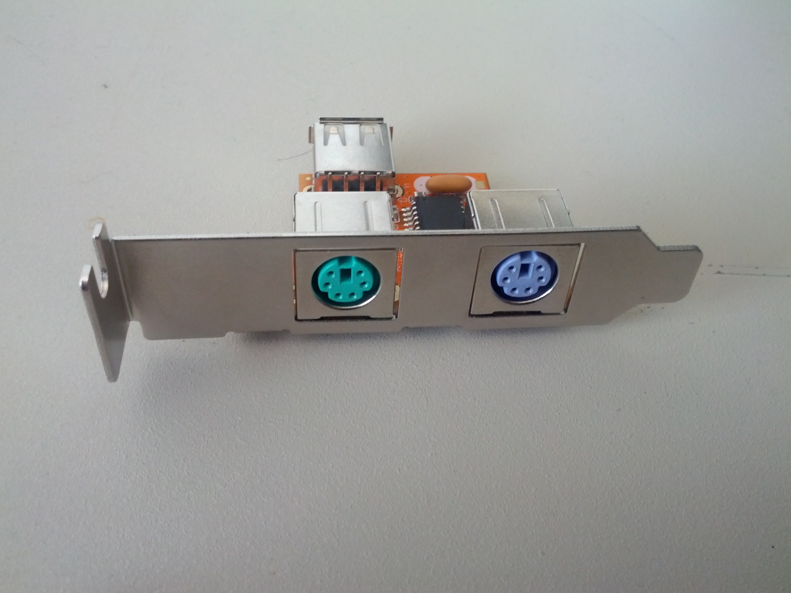
This fits me perfect letting me having PS/2 connectors at the back of the Amiga. So this thing contains some unwanted electronics:
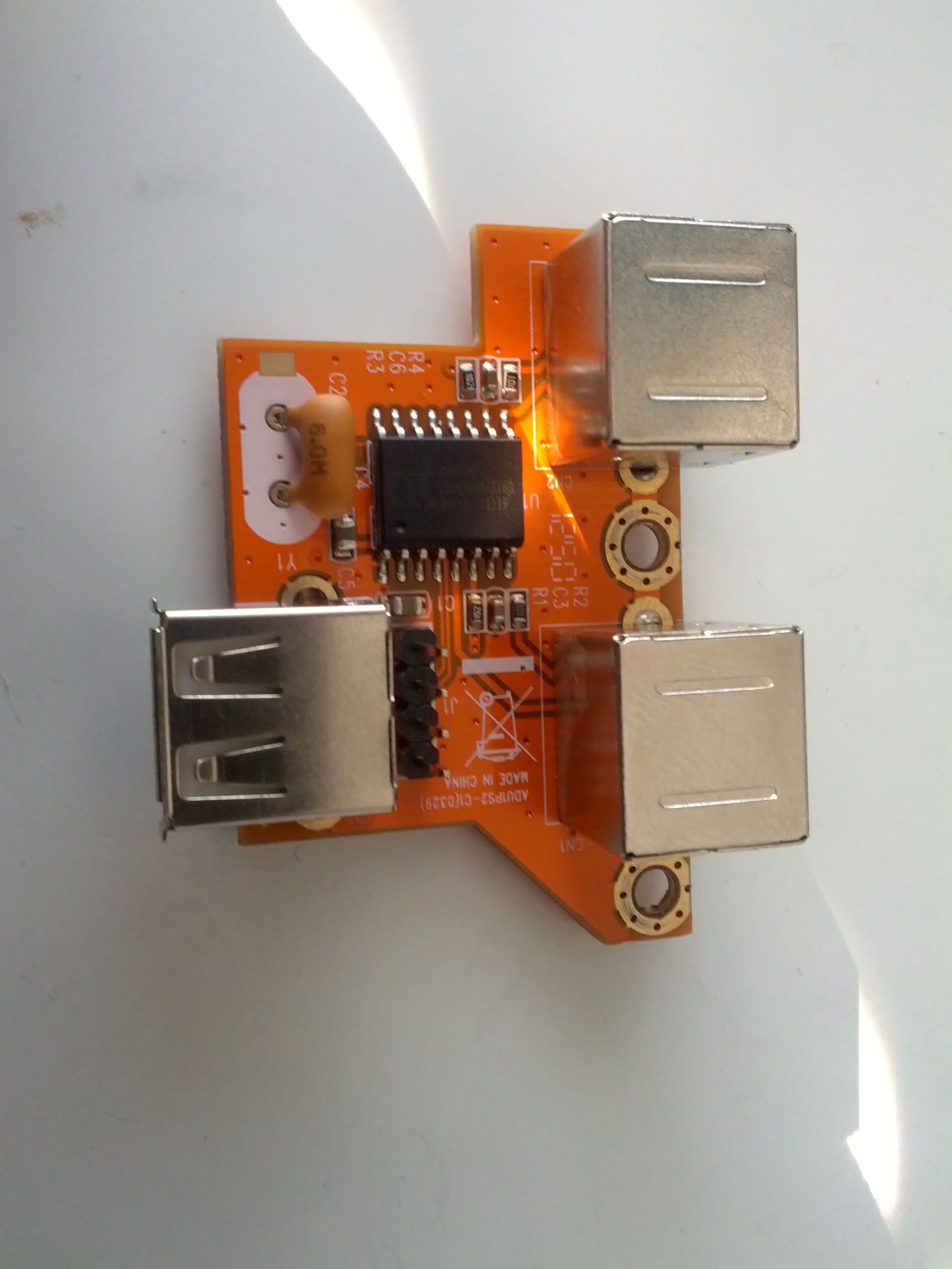
As you can see, it has a USB port, a chip, crystal and stuff. lets get rid of it. and then solder 4 wires per PS/2 connector:
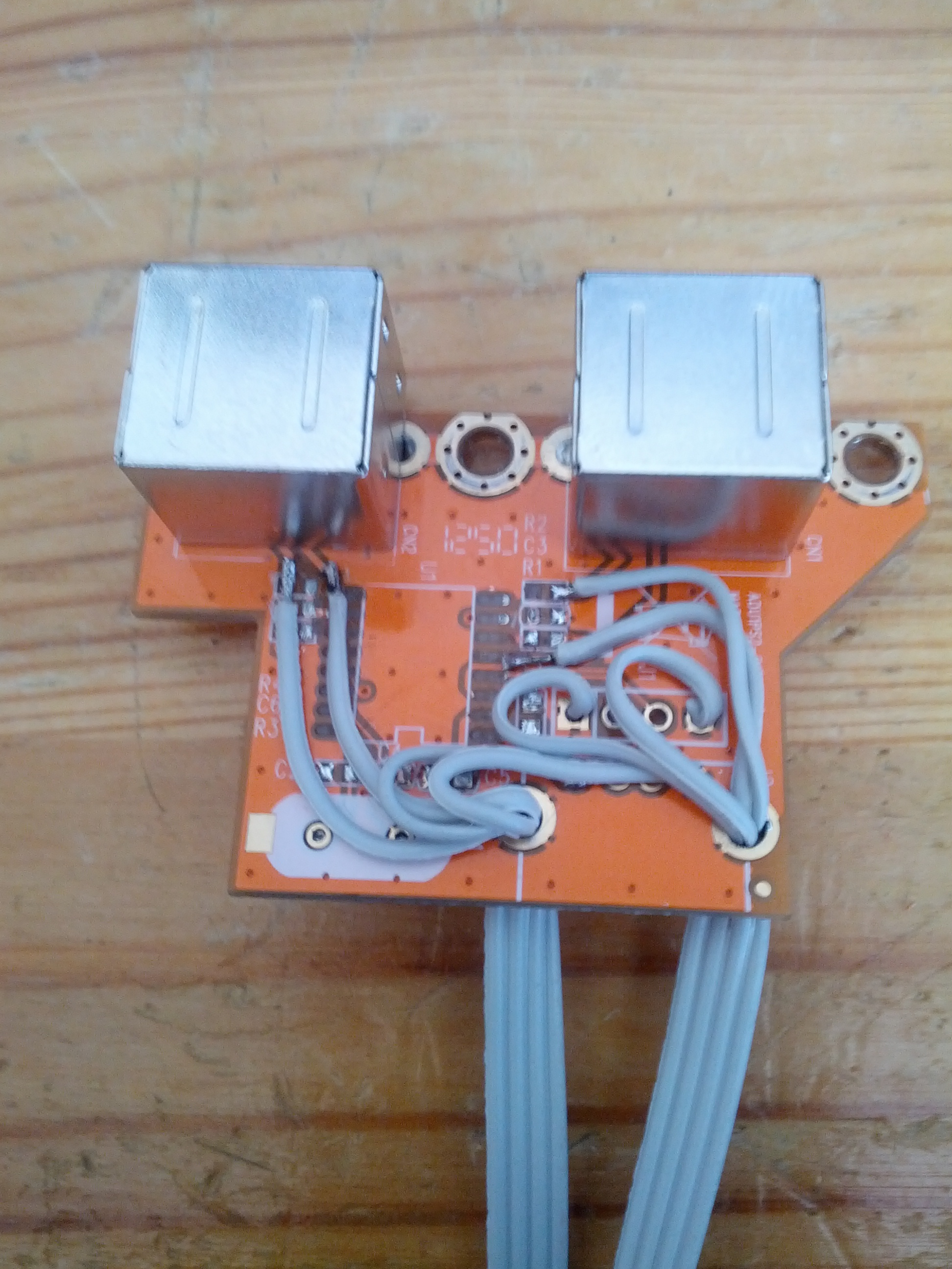
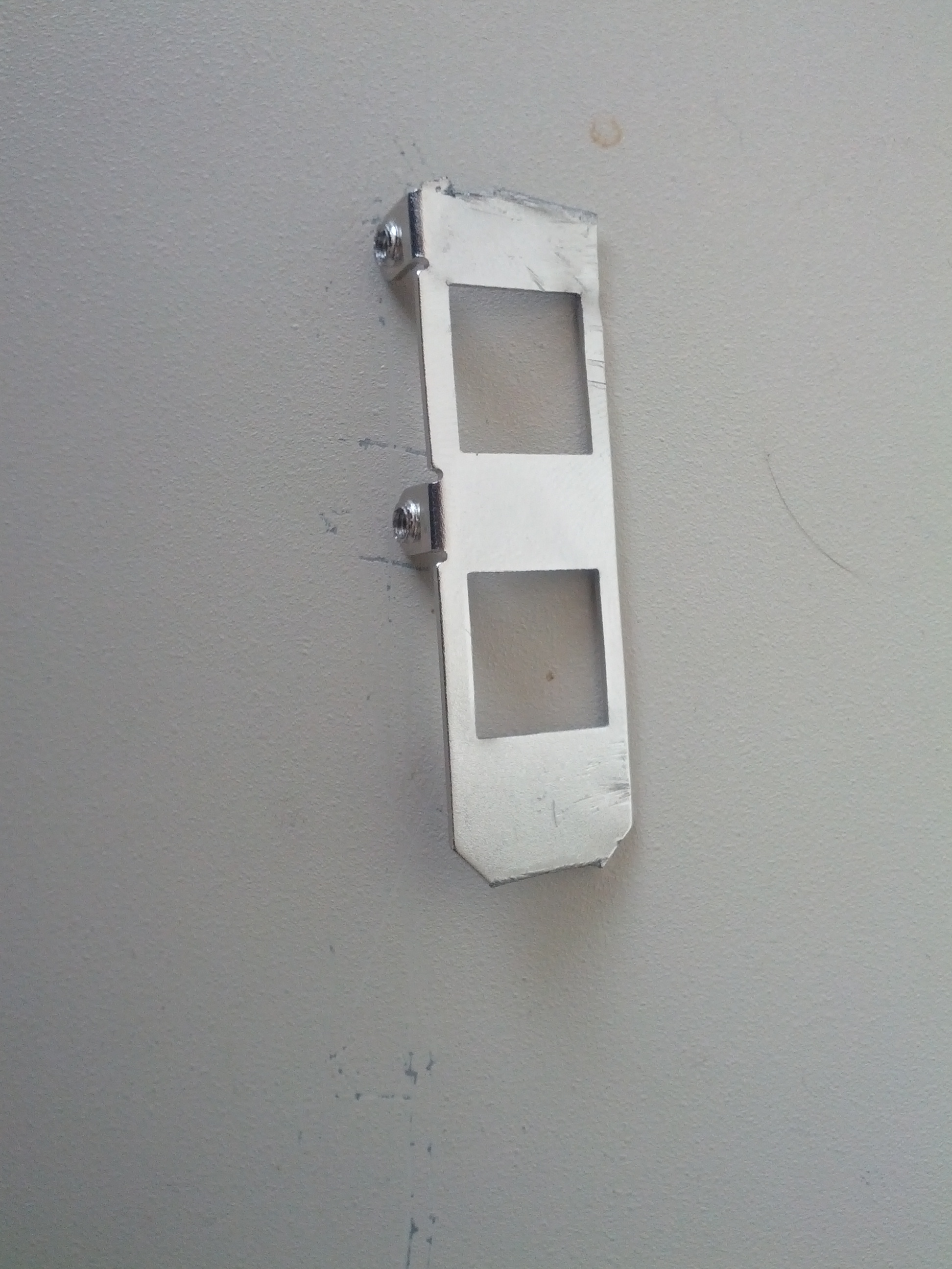
Better, now it is just a normal passive PS/2 Connector, nothing else. Also, time to modigy the metallic sheild so it fits inside the Amiga.
And the finished product:

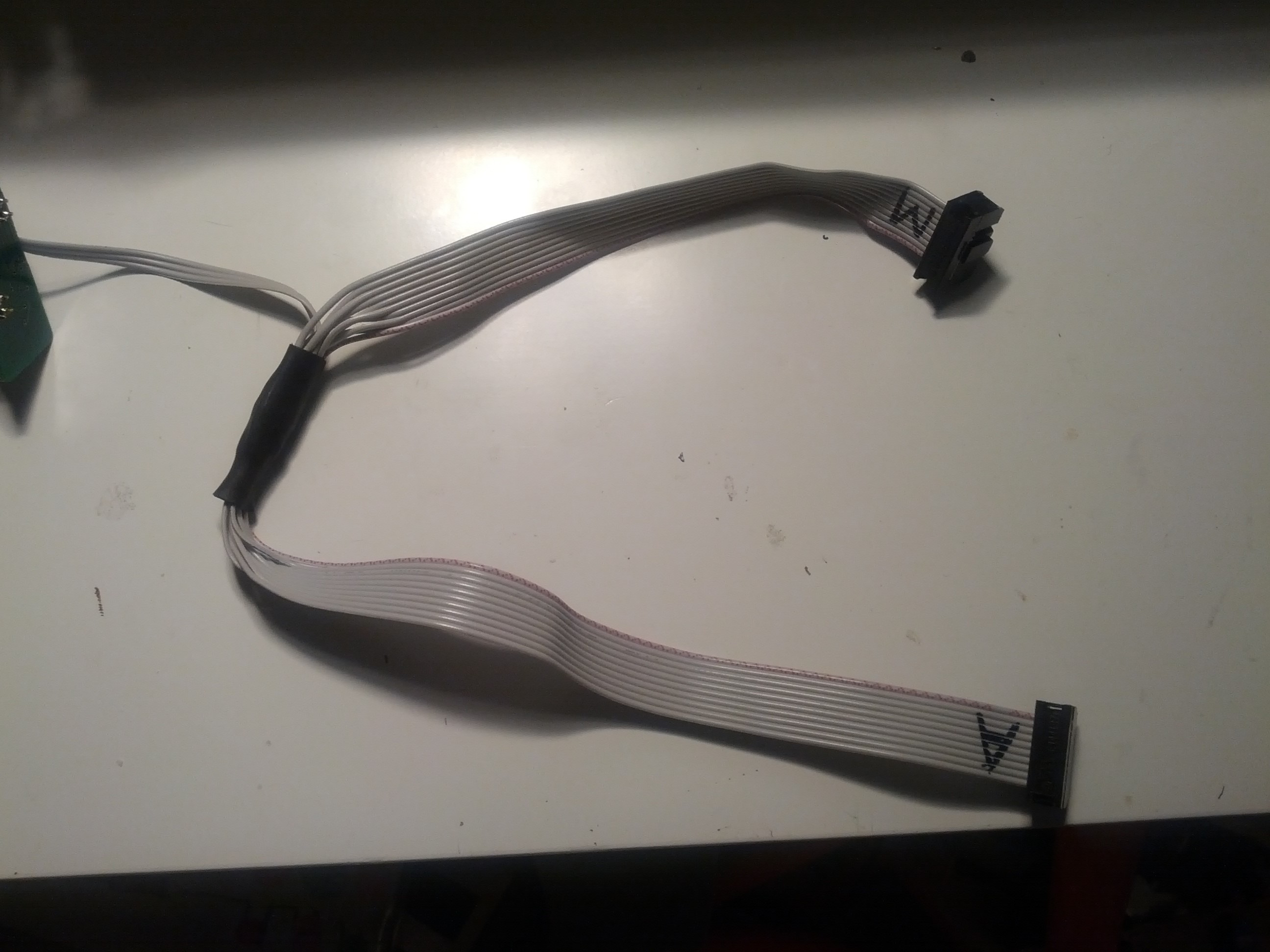
BUT. as there are one drawback with the micromys, when powering on it takes about 1 second before it works, this makes it impossible for me to go to early-boot-menu directly when powering on the machine before it boots. (after reset it works fine) (making it impossible to boot WB3.1 without 3.9 patches) So when doing the internal cable to the micromys, I also make some extra cables for Left mousebutton, Right mousebutton and Ground. So I can have a switch on the side of the Amiga for Early bootup. Pressing it does the same thing as pressing both Left and Right mousebutton at the same time. So I made a little cable to fit the internal mouseport for the Amiga and also stripped out the electronics of the Micromys:
This gave me the bonus of having one slot at the back free for the BVision VGA output signal.
Well. I can’t simply wire together the wires for the Right and Left mousebutton, then I will short that giving me unwanted result. So a small patch on the cable using diods:
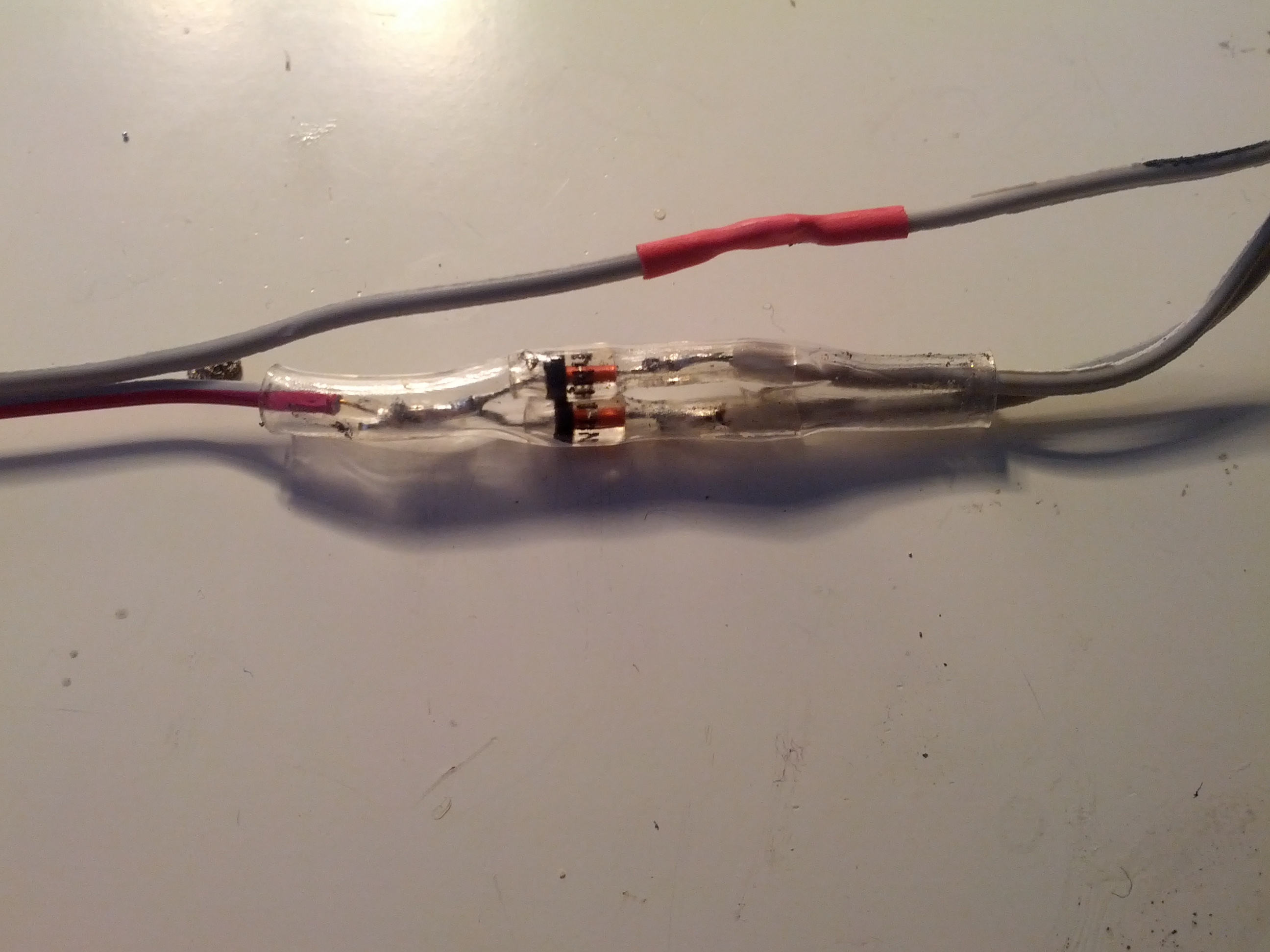
This makes it possible for me to connect both lines to ground witout connecting eachother with a simple 2 pin switch.
Now when I am doing some soldering, I want to ass a NMI (IRQ7) Button on my Amiga.
What is this? IRQ7 is a Non Maskable Interrupt and can be very useful when programming Assembler. Some software like AsmOne have support for IRQ7 so if you make a bad code that crashes in an eternal loop, you simply push that button and VOILA back to normal screenmode and back to the editor in Asmone. it simply breaks the eternal loop and restores screenmodes etc. (If you does not have enabled IRQ7 via software, the machine will only make a pause when that switch is pressed. (and unpaused when you release the button)
So HOW to do this? The Amiga has 3 lines on the motherboard for IPL0, IPL1 and IPL2 if you short all of them to ground, you generate a IRQ7 IRQ.
So. where to find this signals?

Using a magnifier I found theree places that should have this signal. (well there ARE placed on the CPU slot aswell) but.. I didnt like the idea of soldering to the CPU slot, and this does not look lite the best place. Lets search more. and after a bit of google I found a spot on the underside:

R953A-B and C is for the IPL signals. So I solded wires on then.. BUT.. was out of thin wires.. what to do? well. IDE ATA66 cables, they are thin. So I took and cut one cable. Soldering 3 wires:
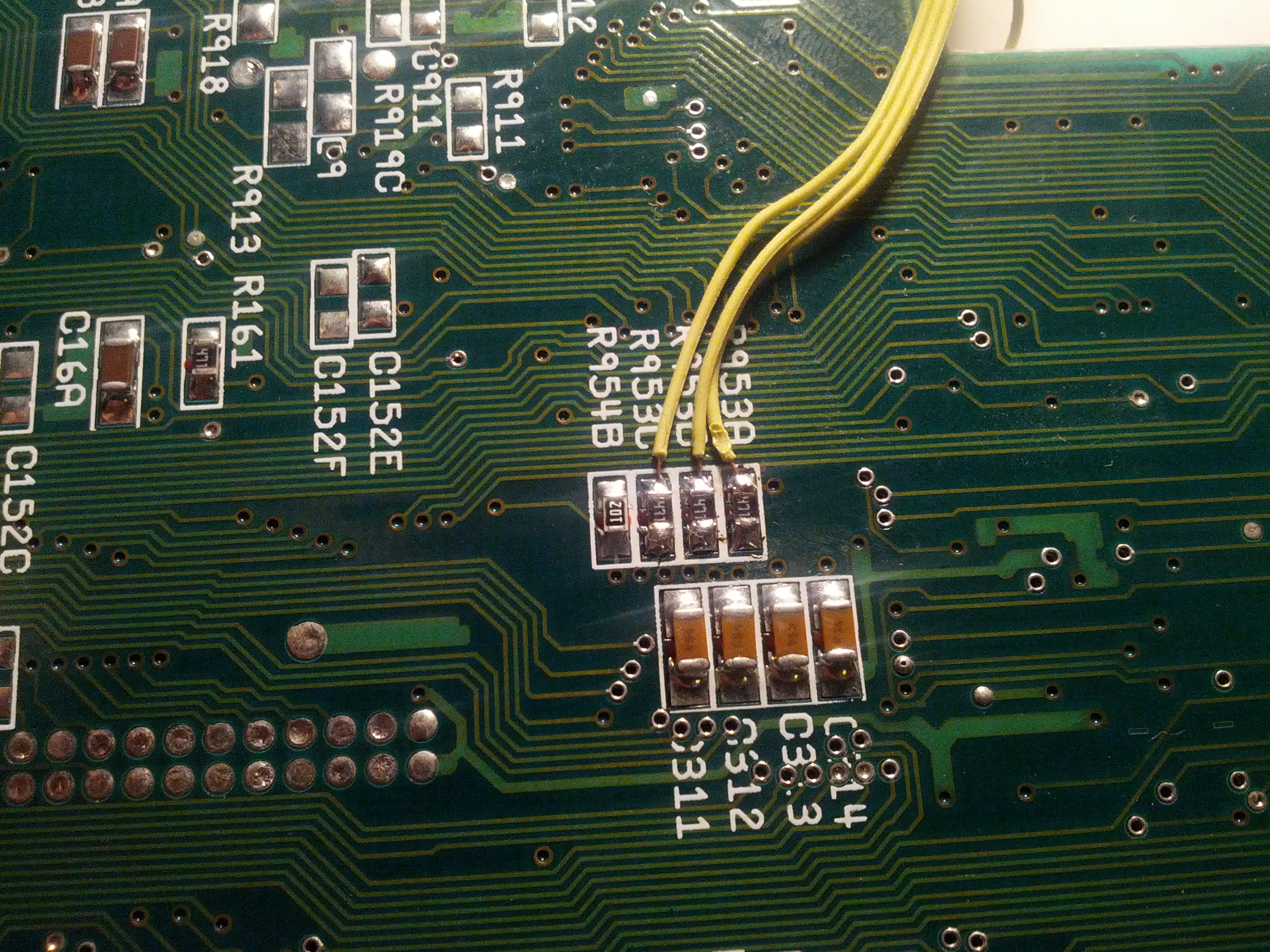
NOTE!!! NOTE!!! that was a bad old photo. I took a photo solderin the wires on the WRONG SIDE OF THE RESISTORS! do the OTHER SIDE!
And as it is the same problem as the early-boot menu, we do NOT want to short IPL0, 1 and 2 but on the same time short them all. so again, diods to the rescue:
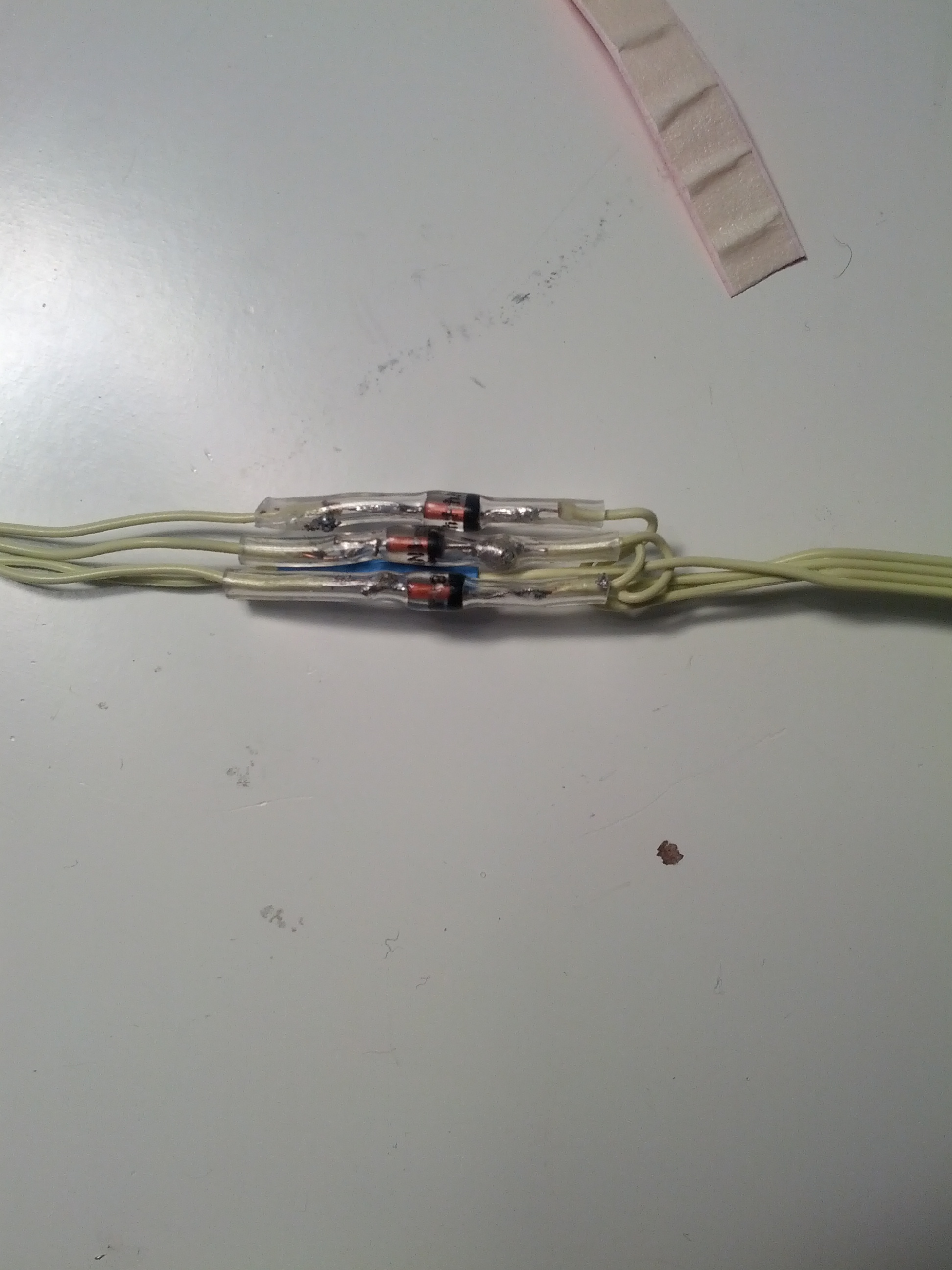
So after the diods, I can saftly short IPL0, 1 and 2 and nothing happens until I connect to ground, with a simple 2 pin Switch.
Now time to modify the case for the extra stuff:
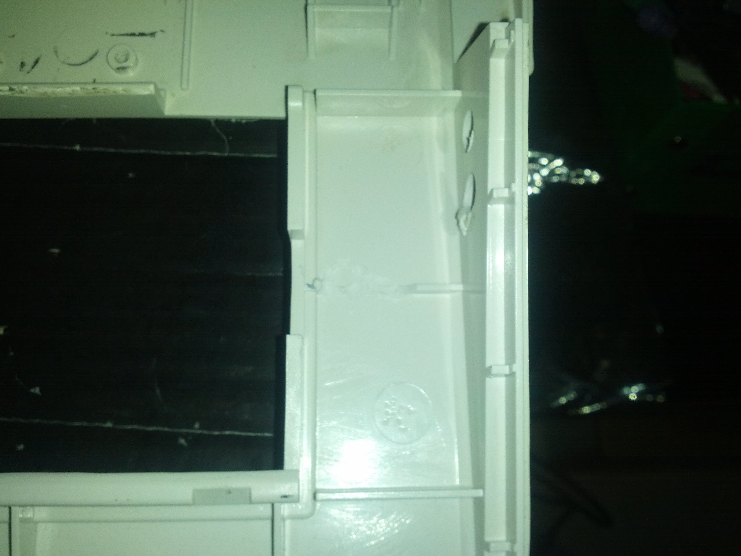

First some mod so the micromys fits close to the cpu slot, and also some modifications so the PS/2 adapter will fit.
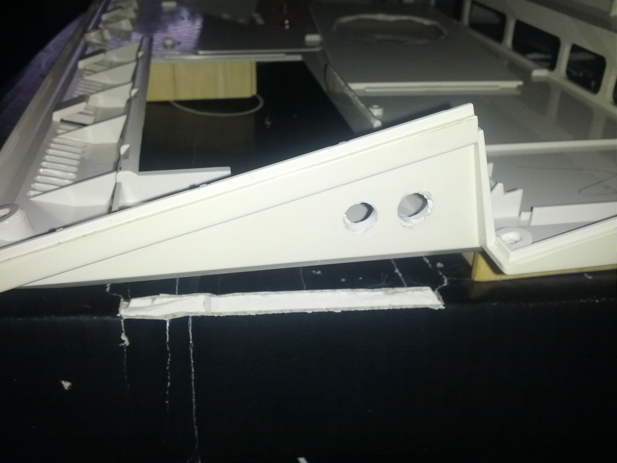

Also make 2 holes for the buttons.
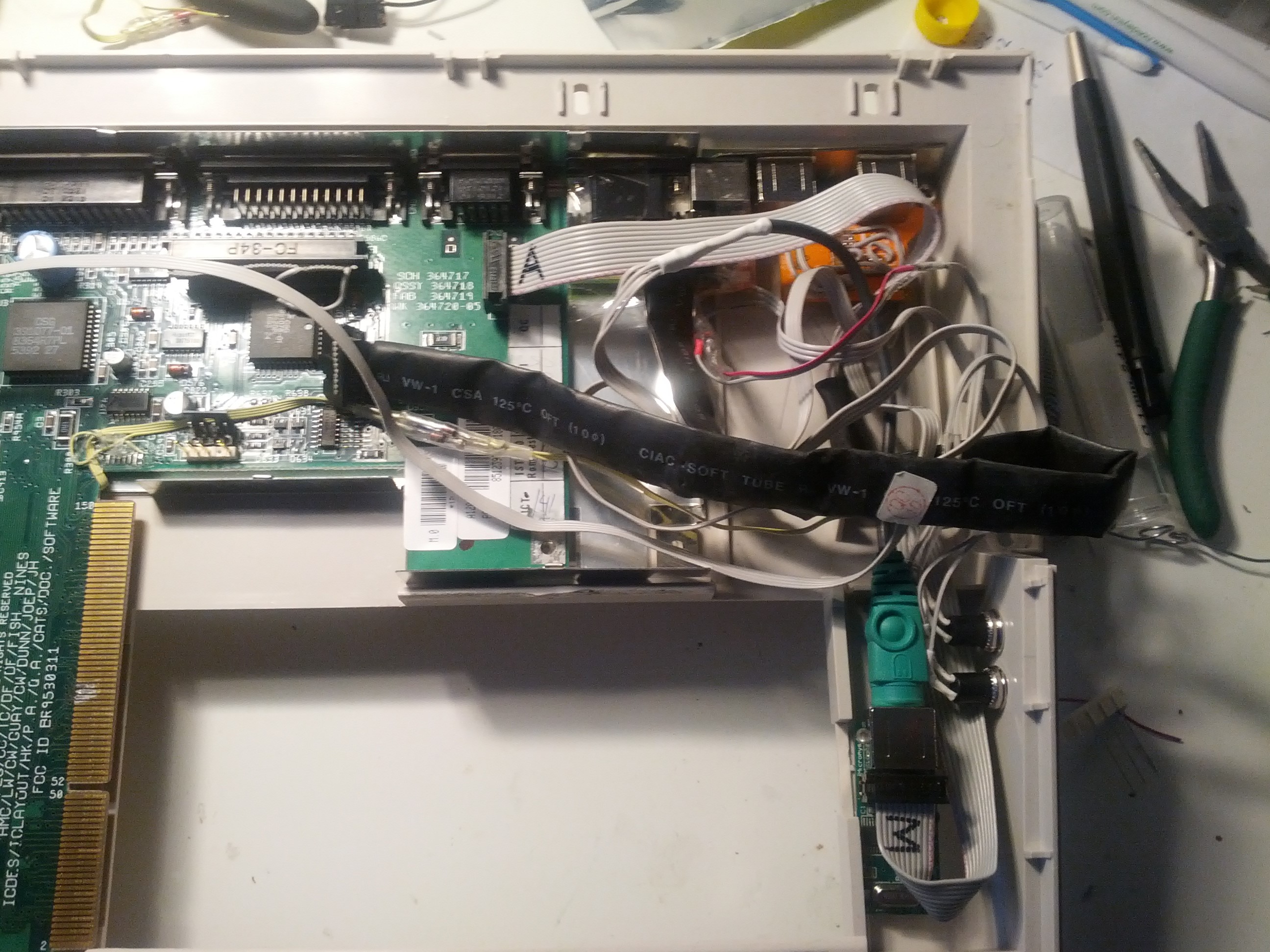
Now fit it all, with cables. This will be cleaned up some more later on. I have ordered a new diskdrive that does NOT have a rotating wheel at the bottom as my old (and dead) diskdrive. So cables will not disturb the diskdrive later.
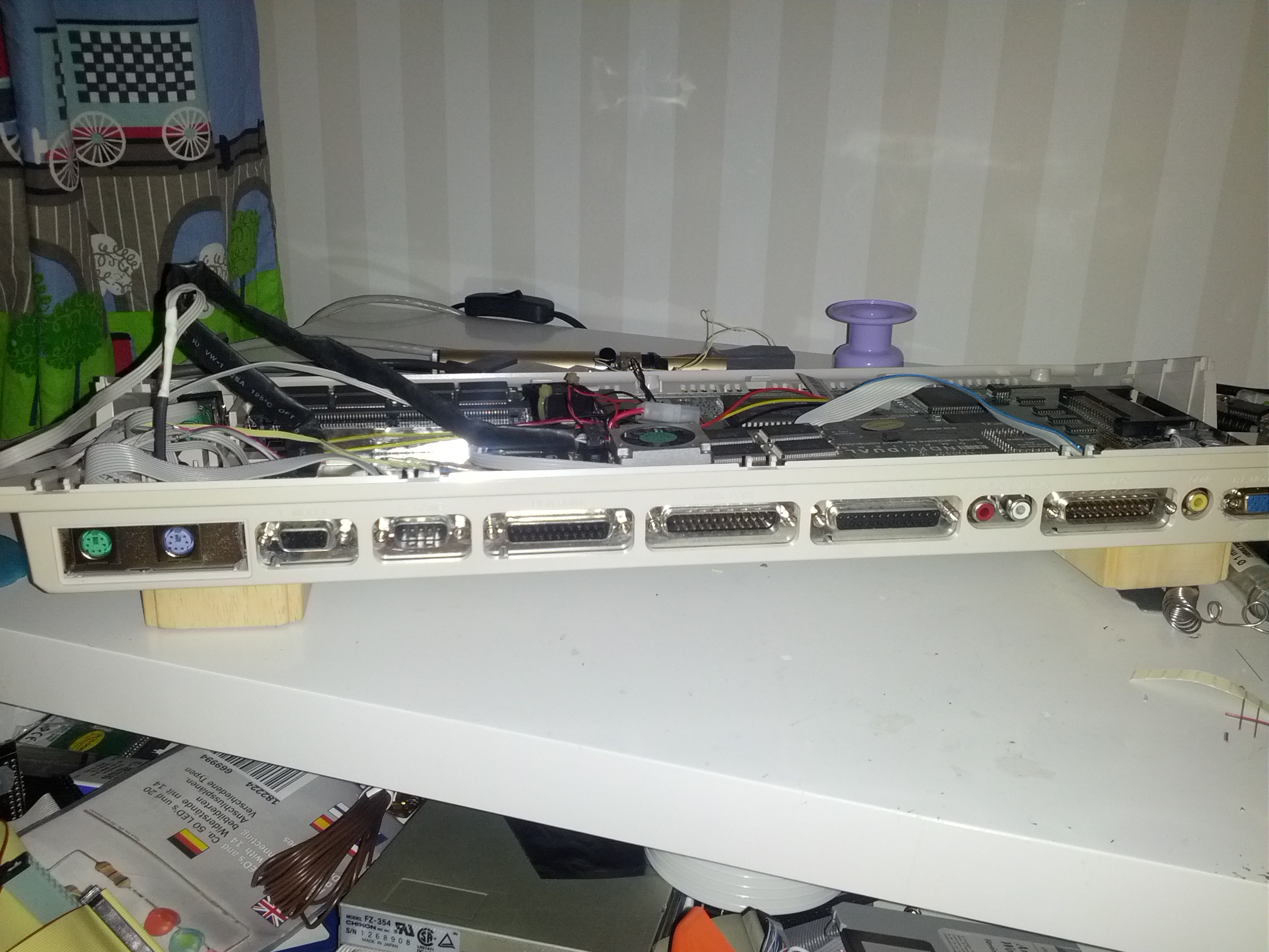
Now you can see how it will be in the end, you can also see the wooden blocks that elevates the machine so the FAN fits on the underside.
We are getting somewhere now. next step will be adding 2 CF Cardreaders to the IDE connector. one for my permanent drive, and one accessible from the outside so I can add another CF card if needed. Also I need to make a better internal powerdistribution for fans, Bvision etc as I only want one powerconnector to the machine, not not with extra molex cables etc. Also. a new diskdrive is required.
Machine is getting stuffed. 🙂 Part 4 will take some time I guess, not enough time…
Three yellow wires in one of the pictures are soldered on the WRONG sides of R953x resistors. It effectively shorts VCC to GND via diodes.
regards
Szymon