This is the Errata post of the ReAmiga project.
DO Check this post if you are doing soldering of ANY revision of the ReAmiga. as this page might change if stuff is found etc.
it works like this: in the title I write what I fond as issues. so if you have a Rev 1.0 board. you need to read the 1.0 header. do those fixes. AND also add fixes for 1.1, 1.2 etc.. (unless mentioned in the text)
ReAmiga Rev 1.0 TESTVERSION (note this is the TESTVERSION it have this also printed on the PCB! to NOT mix with the released Rev 1.0)
D232A, D233A and D231A have its top pins connected to GND. you need to cut that connection and solder it to VCC.
VGA Connector is not connected to ground, middle row of VGA Connector needs to be connected to GND. holes for securing VGA Connector is grounded.
RTC C918 Plus is connected to Minus. so. RTC onboard is not possible on this PCB! do NOT install it.
R329 Bottom pad shold be connected to LF347 Pin 9
OP led incoming optional signal. right hole is connected to ground. do not use it.
PCMCIA reset is totally wrong. do not use! if you will build a board with this contact me.
All other issues taken up here also aplies to this board EXCEPT the Rev 1.0 Powerissue. (and video power +5V)
ReAmiga Rev 1.0 (This is the first released version. does NOT have the “TESTVERSION” printed on it)
There was a BIG mishap on the powerconnector. If you are using a square din for power. you MUST cut a trace or you will have a +5V short to ground:

Also while moving one cap for better location. videopart lost its +5V connection so you need a jumperwire:
(YAY for Sprint and no schematic-checking)
Rev 1.1
(includes fixes listed for 1.0 already, you can skip those)
NTSC Misshap. this is only if you will use your machine as NTSC:
R62 you sholuld have a 0 ohm resistor from middle to right. however right position is connected to ground this is wrong.
so instead of a resistor, solder a jumperwire to the middle pad and other end to RGB (not VGA port) pin 15.
IF you are using a VideoDAC that requires a zenerdiode. do not populate C215 with a 1uF cap. instead put a 1K resistor on the RIGHT pad facing down.
on the other end of that resistor. solder a wire from that to a top pin of D233A or D231A to feed that resistor with +5V instead.
Rev 1.2
(includes fixes listed for 1.0 and 1.1)
U10 74F32
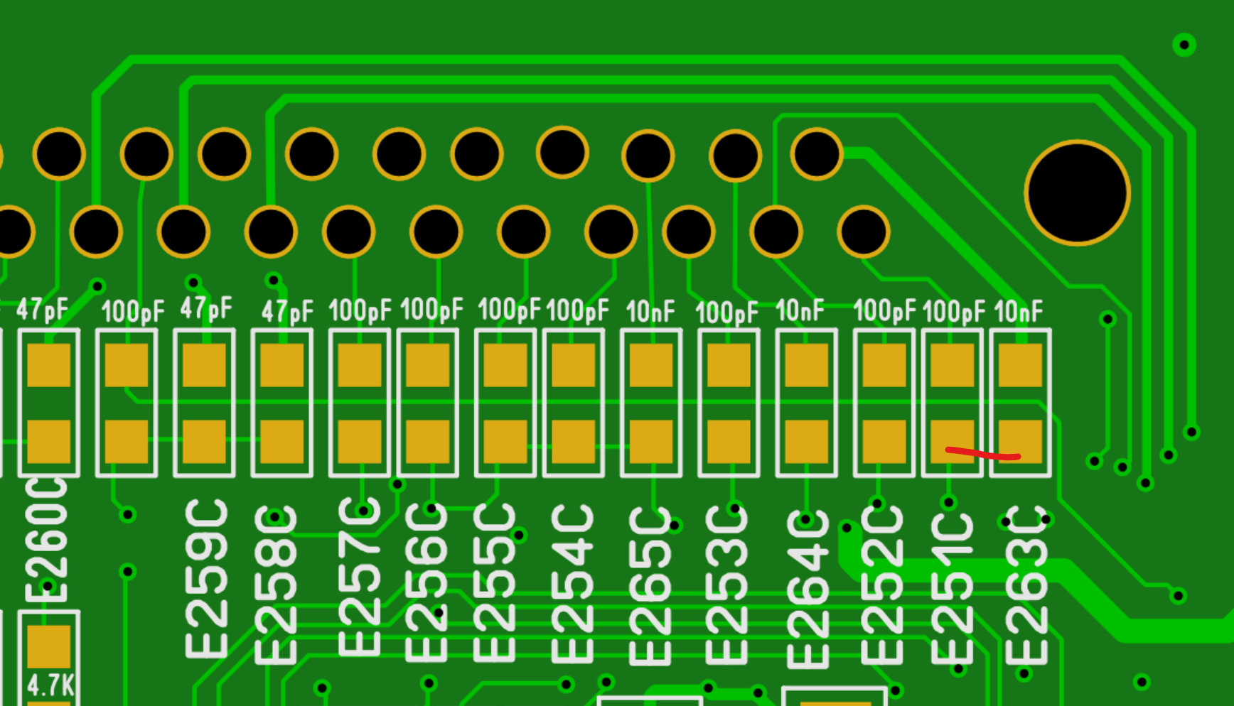
this is the big mystery. it seems to work. but this chip does not get power. so if you have noscreen issues (just flashing colors on Diagrom but no picture) pin 14 of this should go to the 47nF cap XC1 RIGHT pad. NO idea how it really works anyway 🙂
Audio Resistors R301 and R302 is marked 100Ohm. Should be 10. Works anyway but. right should be right:
Resistor R951C at CPU is marked 470ohm. should be 4.7K. seems to work anyway but.. well..
Rev1.4
This fault is ONLY on the Rev 1.4 PCB and happend when ironically clearing up some space.
C0D cap is touching a trace. easy fix of this is to remove the cap and cut the trace to the GND. And simply skip that 47nF cap.
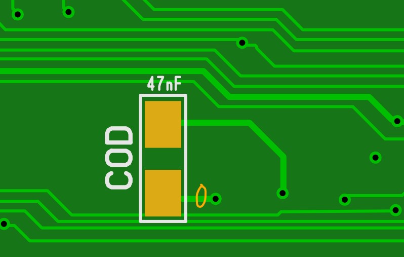
However strangly enough it seems to work anyway!
Files on www.reamiga.info is corrected (Rev 1.4.1 have this fix (only change on PCB) so CAP can be located. )
Rev1.5
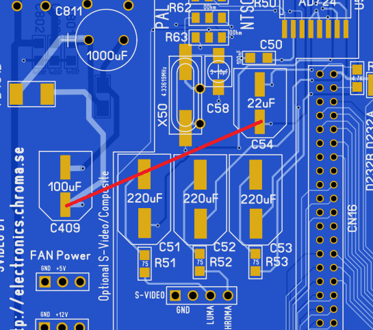
This is for all ReAmigas. a small decouplingcapacitor seems to be missing connection to GND.. just solder a wire as shown in red and it will work fine. withouit this being done there is no serious issues with it but MIGHT cause instabilitys if there are a high draw due to a device connected to the RGB port drawing alot of 5V. an adapter with a buffer etc would most likly not be an issue!
Thanks for the Rev 1.2 update!
You are welcome
Hi !
First of all, Happy New Year !!!
Excellent work, thank you !
Will a Budgie REV.:1 391425-02 Chip work with PCB versions 1.1 & 1.2 ?
Because I´m trying to build my two boards with as many NOS-components as I can find.
The problem is the I can not find a Budgie REV.:0 only the newer version.
greetings from Austria
i have not tested it. but it should work
Hi Chucky,
just wanted to note that C307 (470uF through hole electrolytic) is missing from the component locator.
Best,
Torsten
Regarding the U10 mystery – the board I just built here works fine without that part fitted at all, so I guess working with the chip not getting power is basically the same thing.
might be so..
Hello.
Could I get the Reamiga1200 scheme in pdf file.
I greet.
there are no schematics. but it is pretty close to the Amiga 1200 schematics anyway
https://www.amigawiki.org/doku.php?id=en:service:schematics