As usual on all my guides: PLEASE Read the guide first. prefferbly BEFORE ordering components or so. also follow it. the reason why you do it in steps is to catch errors so you do not have a completly built board and then try to start it and it will not start.. and if stuff doesn’t work as in the guide: check what you have missed. if it is not in the guide: I have not idea either. 🙂
The CD32 is very special, so if you lack a component from the BOM. it means you will need to transfer it from a old board.
Anyway as usual. put all passives on the board. Resistors, ceramic capacitors, diodes etc. leave the electrolytic capacitors. A note about U14 and U49, on the original CD32 it is using a component that are not produced anymore. you can use that one OR the small 3 pad (SOT-23A-3 ) location with a TC54VN4302ECB713. NOT both.
AND CD32 have a addon throughhole resistor at U49, this is not needed as it is fixed on board.
(Most of this guide works for CD32 clone aswell. but you are on yourself when it comes to parts I have changed in the ReCD32)
Anyway Locator for the project you can find at: https://locator.reamiga.info/locator.php?project=ReCD32
Project webpage for the ReCD32 you can find at: https://www.reamiga.info/?page_id=148
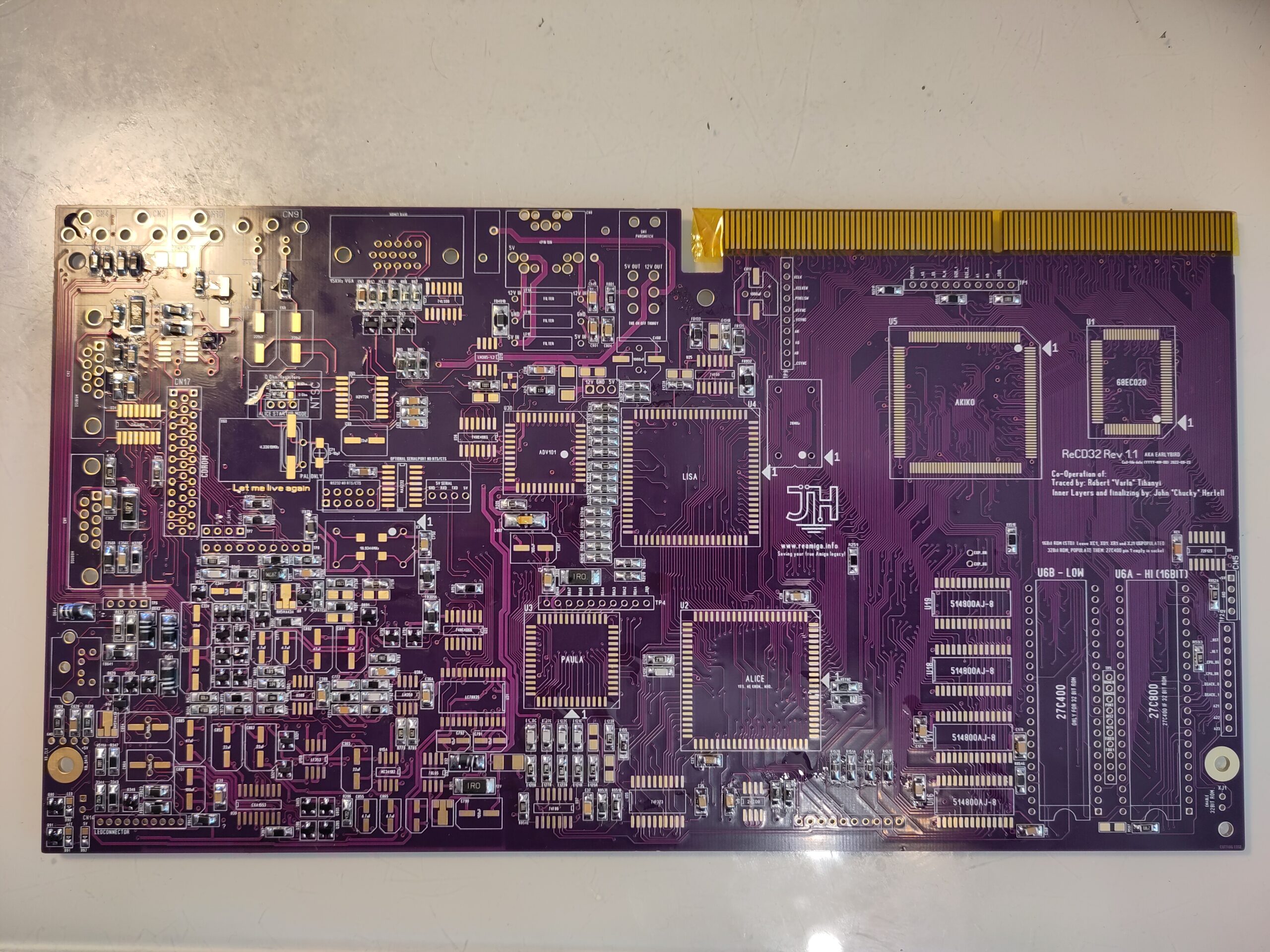
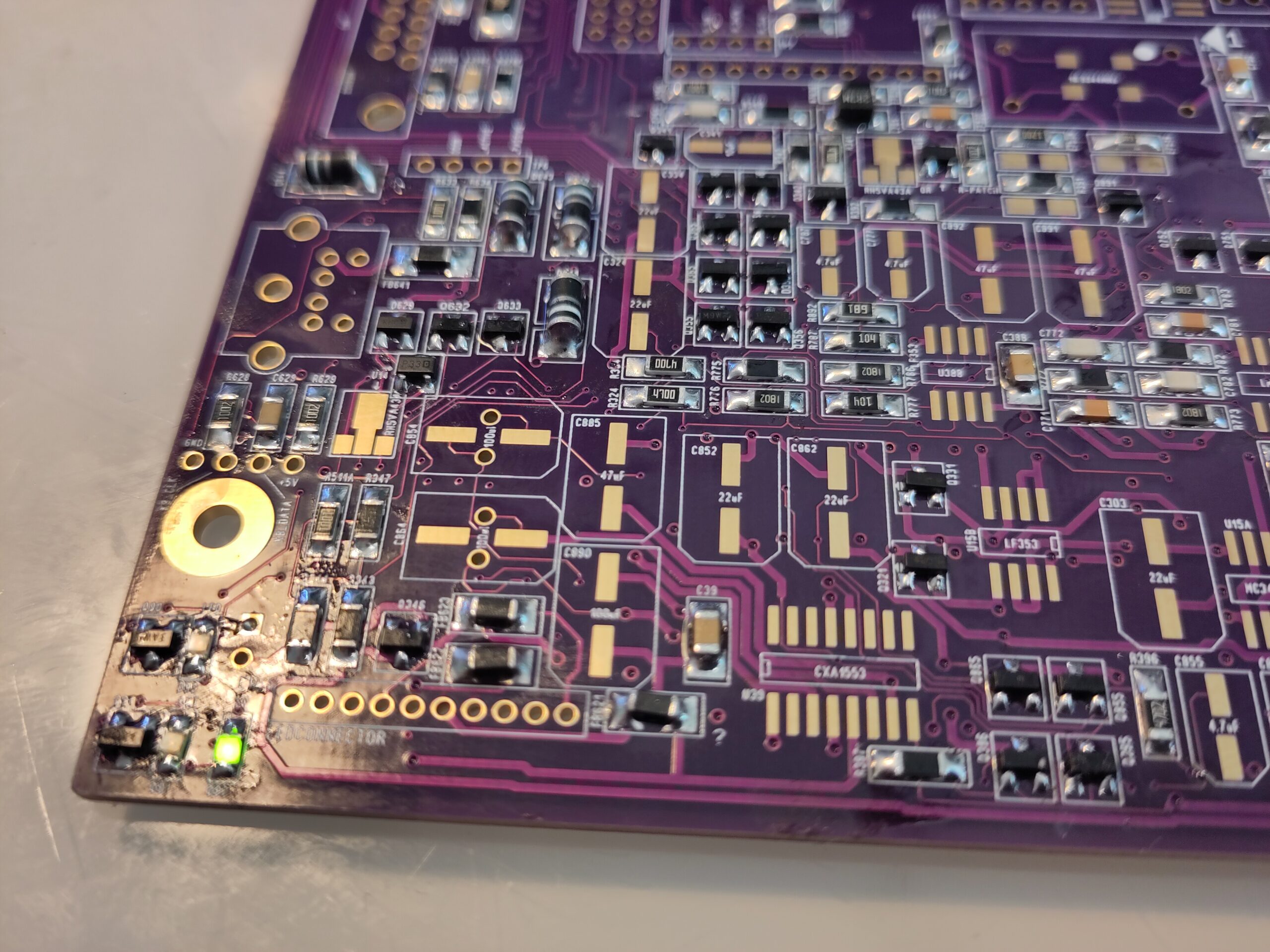
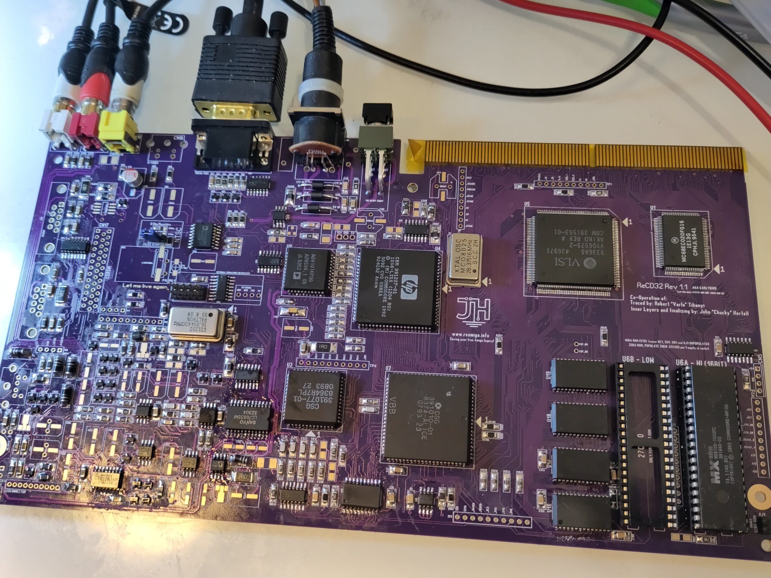
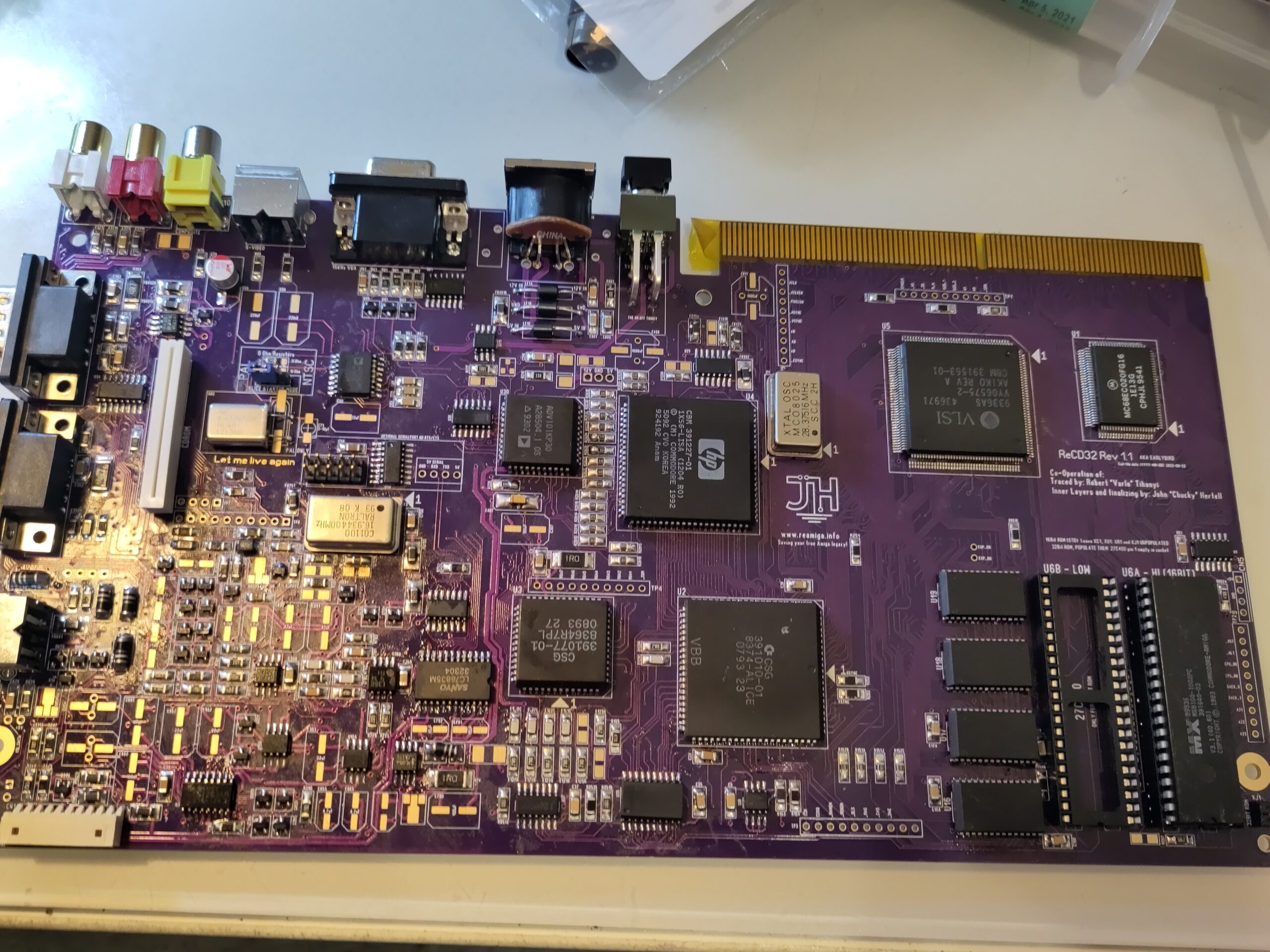
Anyway. A board with all passives on:
First time to get power to the board.
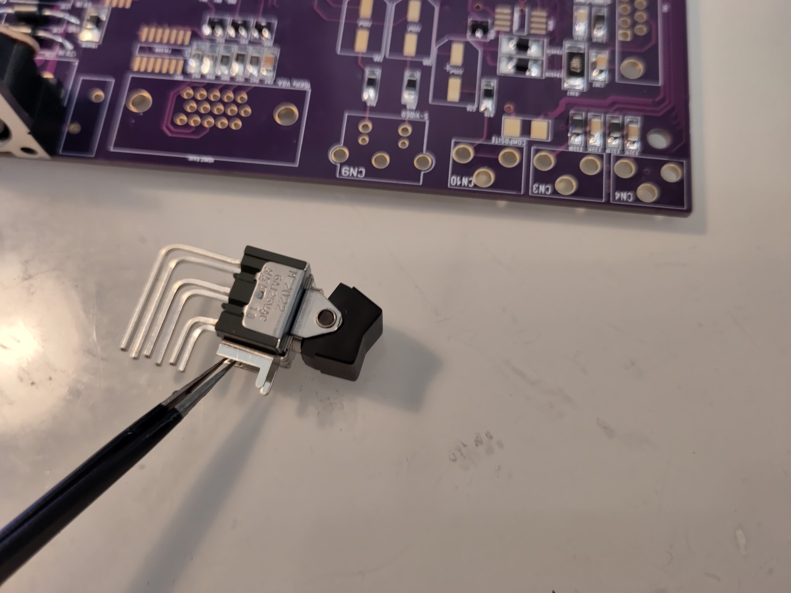
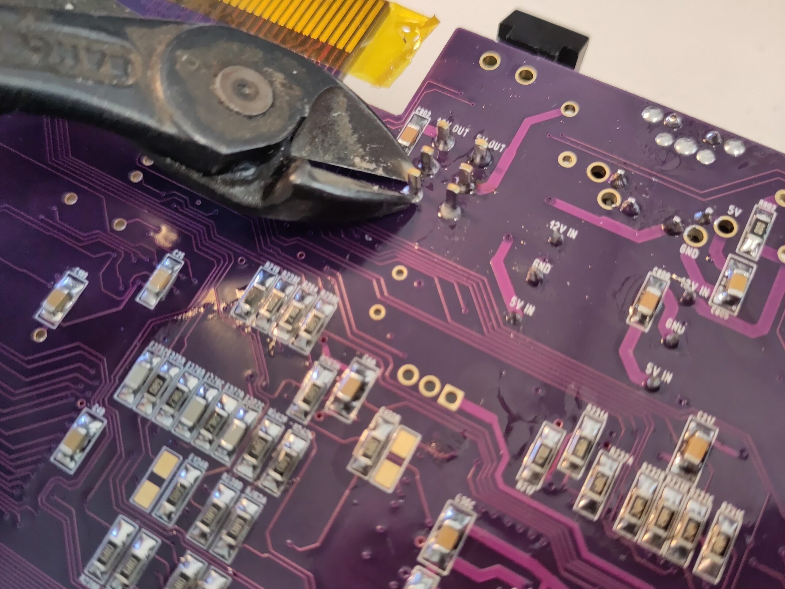
Solder in the Powerconnector and 3 throughhole ferrite beads as filter.
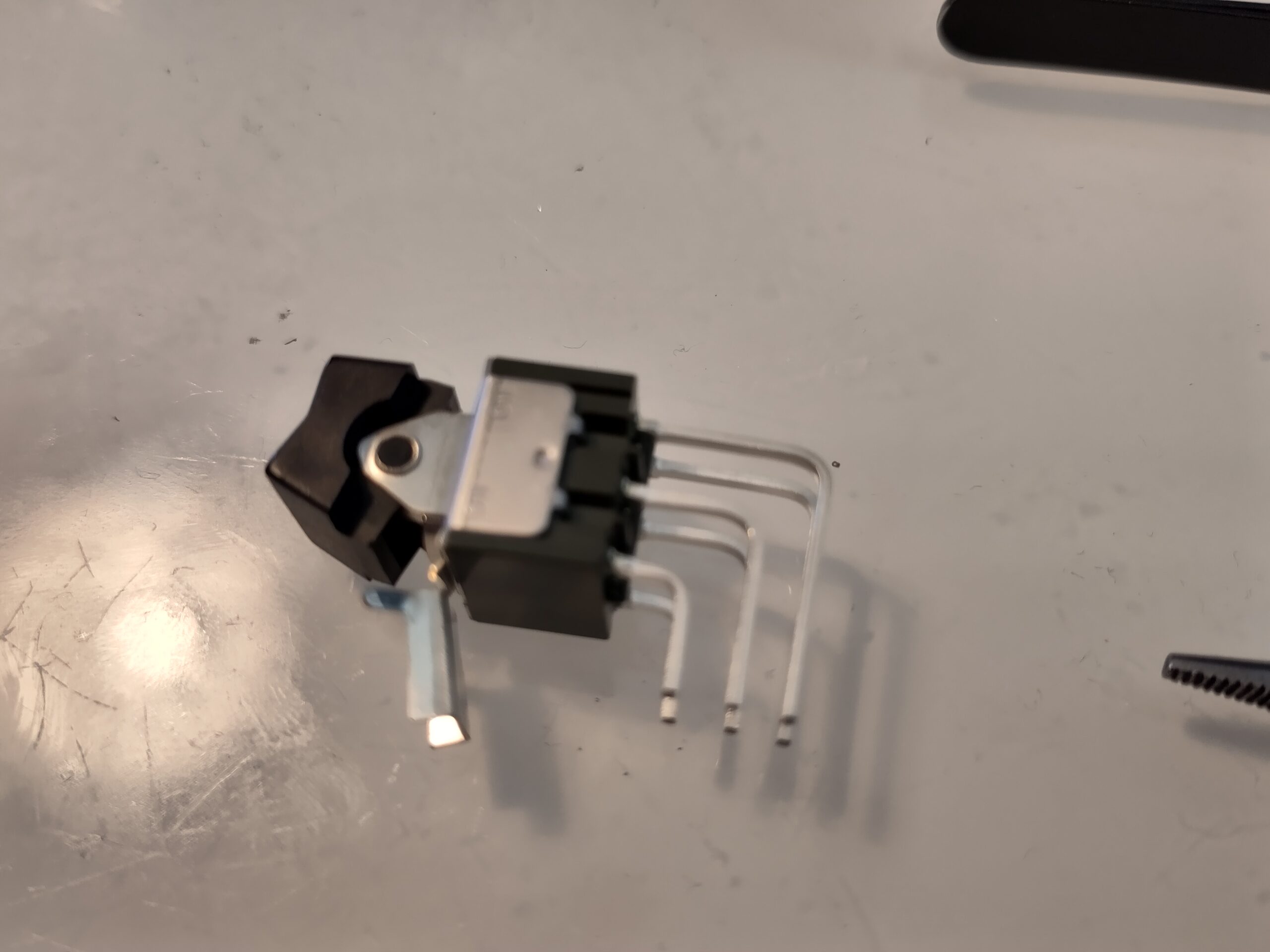
A note. on the BOM I have the switch is not 100% perfect. it have a small distance:

All in place and power it on:
The led for +5V will now go on.
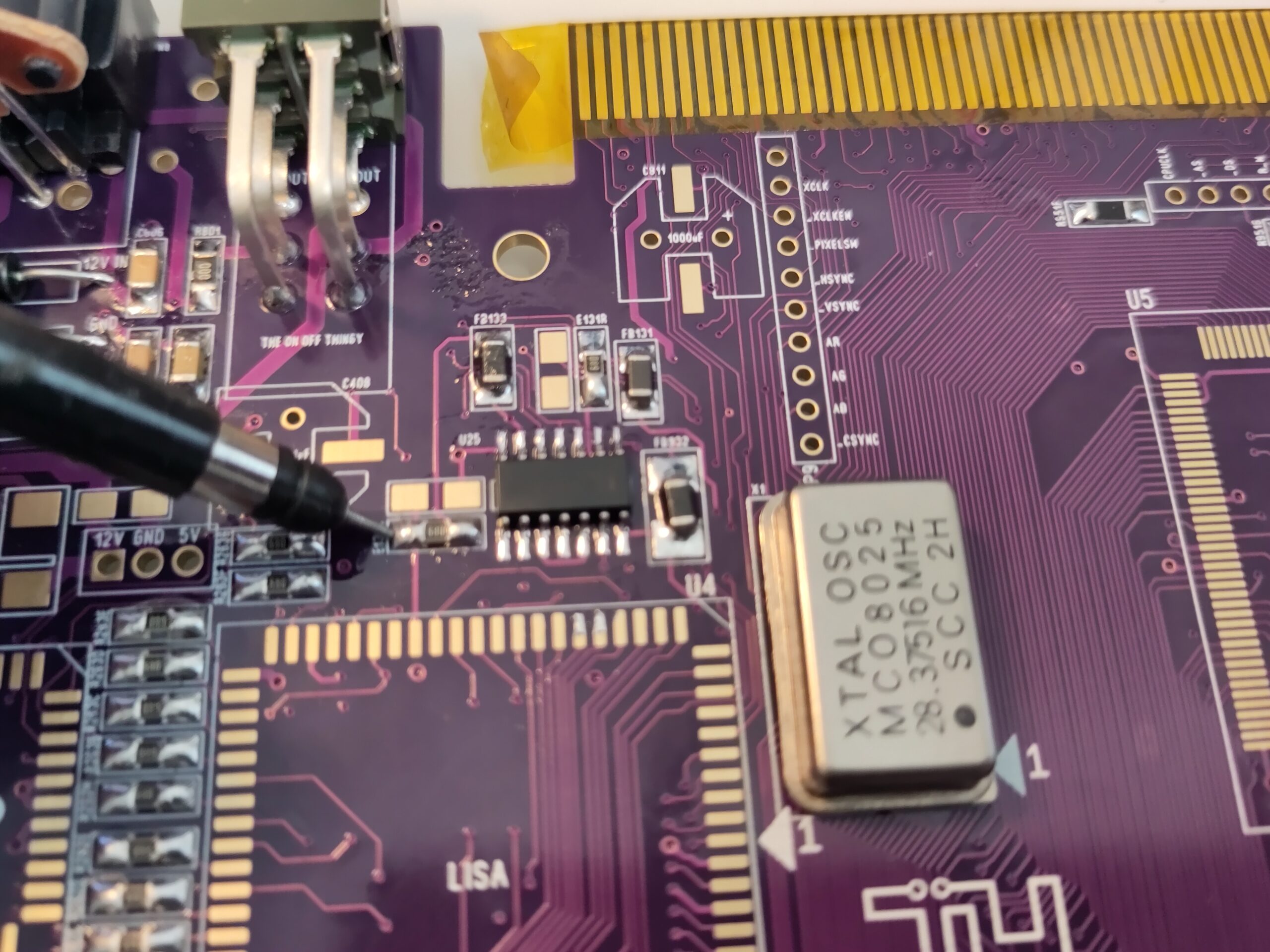
Time to add 28MHz clock:
Put in the 28MHz oscillator (ACTUALLY for a more easy build do this AFTER LISA but I want to point out what is needed for the 28MHz to work.
U25 (74F00)
Now there should be a 28MHz systemclock. (but as told. wait with the 28MHz AFTER you soldered in LISA) even if I now show picture with 28MHz in place: (probe where you can check for a 28MHz signal)
Add LISA, ALICE, AKIKO, U61 (74LS08), U34 (74LS166) and the VGA Connector.
(and the 28MHz oscillator if you haven’t put it in yet)
(CD32 clone builders cannot do a VGA Connector)
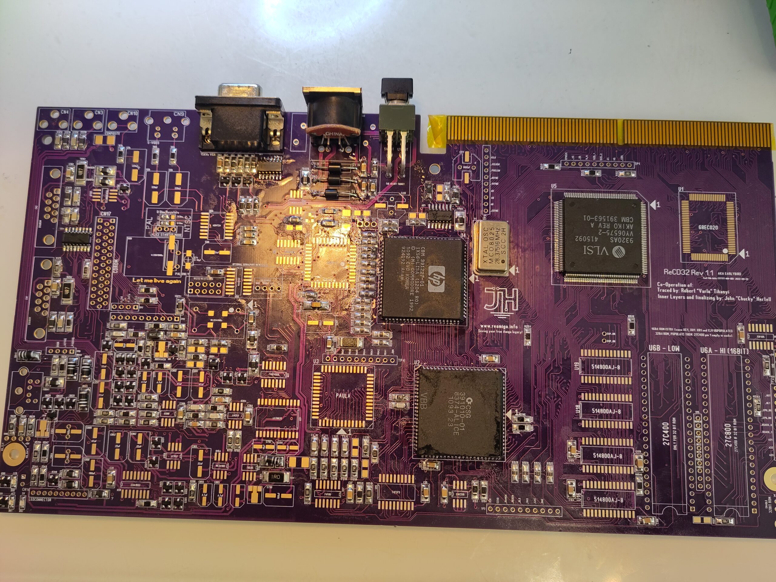
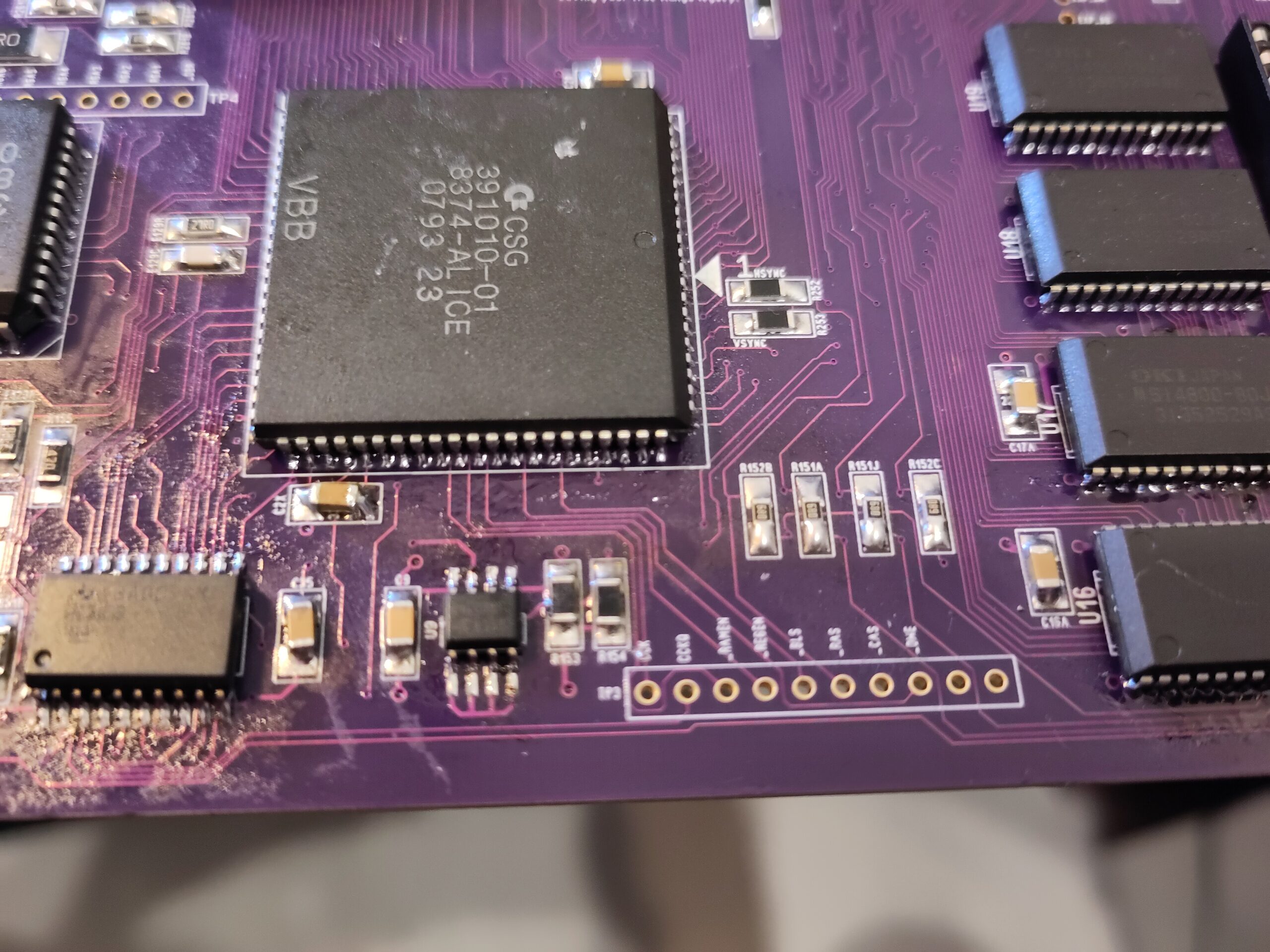
You can now get a (15KHz) sync on the VGA Connector. OR you can probe V and H sync on the left pad on the 2 resistors right of ALICE. or one of the testpoints of the board.
Now time to get some code running.
First. in this build I am using 32 bit roms instead of standard 16bit. Remember that the BOM includes stuff for this. so if you do NOT want to use 32 bit roms. you can skip one 42 pin socket (U6B) also you can skip XU1 and the jumper. (remember to remove from BOM when ordering).
HOW to burn 32 bits roms etc. this is not the guide for that. it will be up to you. Anyway the rest here is with 32 bit roms.
Anyway add XU1 (74F125) (SKIP this for 16 bit (original) ROM)
Add jumper-header for 32Bit rom at right botton. (and put a jumper there) (SKIP if 16bit)
Put in ROM sockets (ONLY U6A for 16 bit)
Put in CPU and U37 (74F86) (NOTE: on OLD pre-release CD32 boards from me silkscreen is wrong way on PCB. follow direction on the locatorscreen).
Put in DiagROM as rom.
Cpu now runs code, you will note it if you probe data/addresspins on the romchip that there is activity.
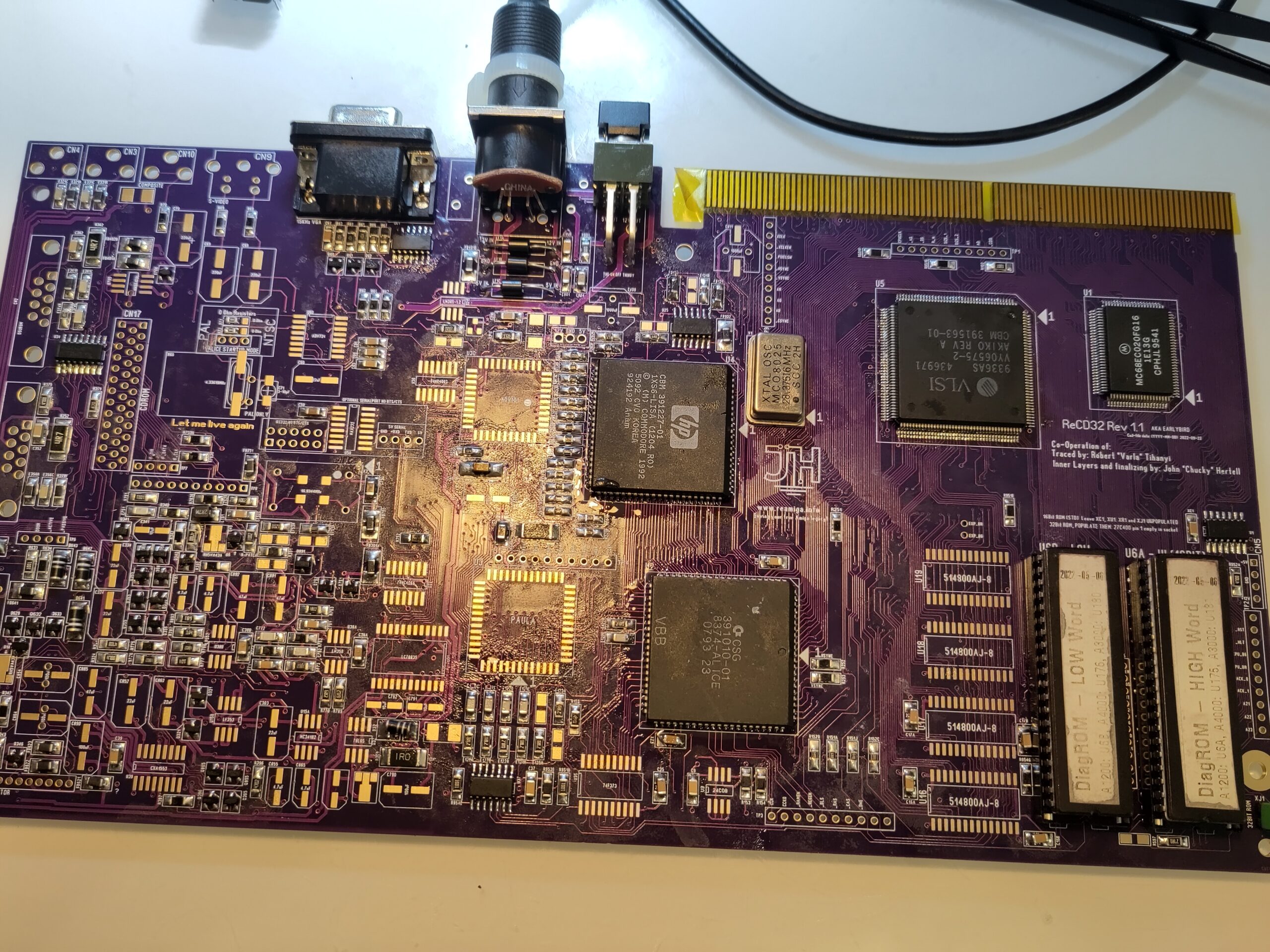
Here you see with 2 roms (32bit) also note that the bottom pins are not used when using 27c400 proms. (same as on 1200 etc) for 16 bit you have a 27C800 prom at the right socket.
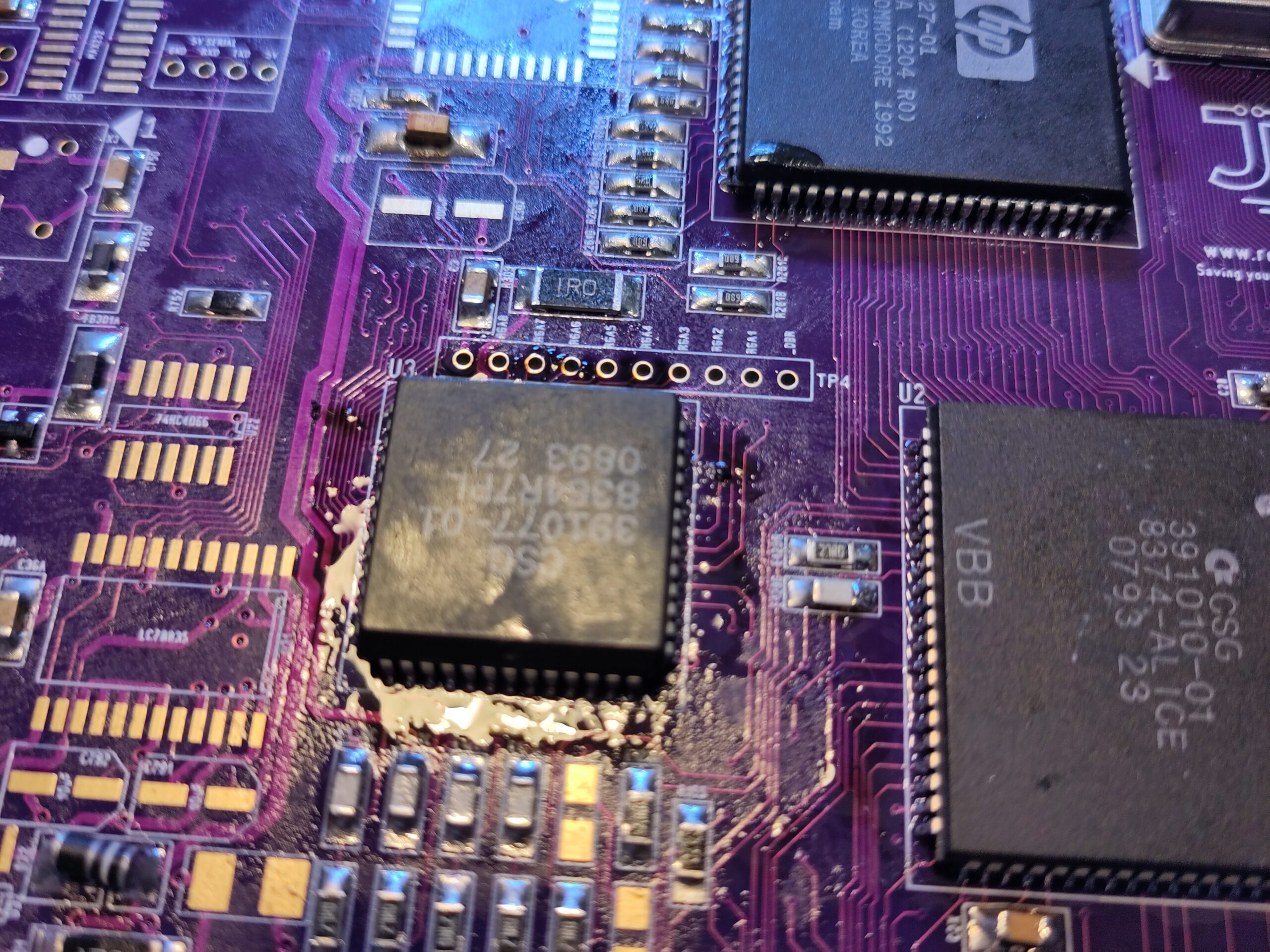
Next step is Paula so add it. (NOT. prerelease CD32 boards, Silkscreen is wrong! put paula as in locator (and original board as shown on picture):
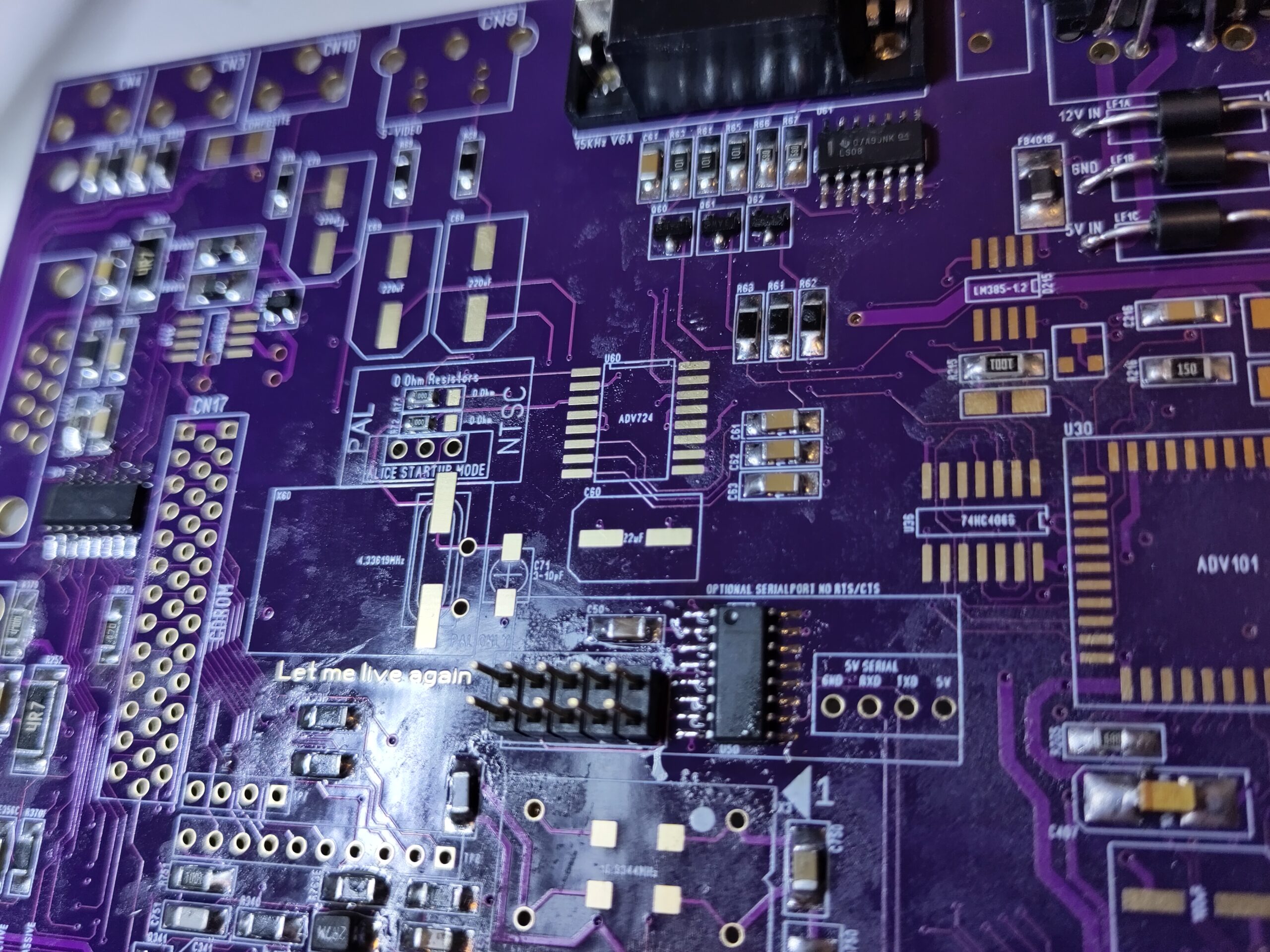
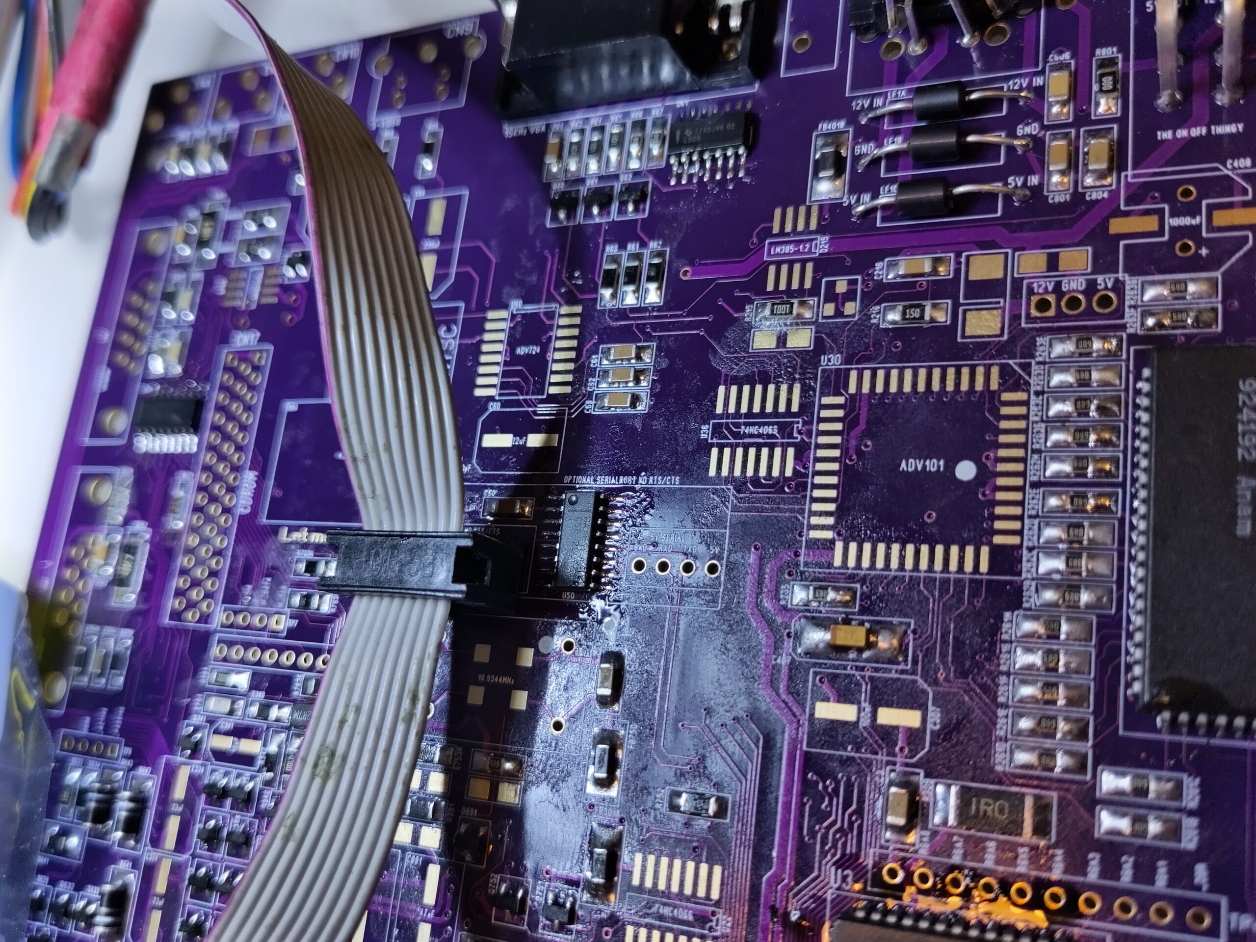
now time for a OPTIONAL addin: the serialport. (NOTE this serialport does NOT handle RTS/CTS handshaking) this is FULLY optional and not needed. (BUT is in BOM so remove components if you do not want it). there is a location for a header if you are happy with a 5V serial signal but as normal serialport does not use 5V. I added this feature.
Add U50 (MAX232)
and the 10 pin header.

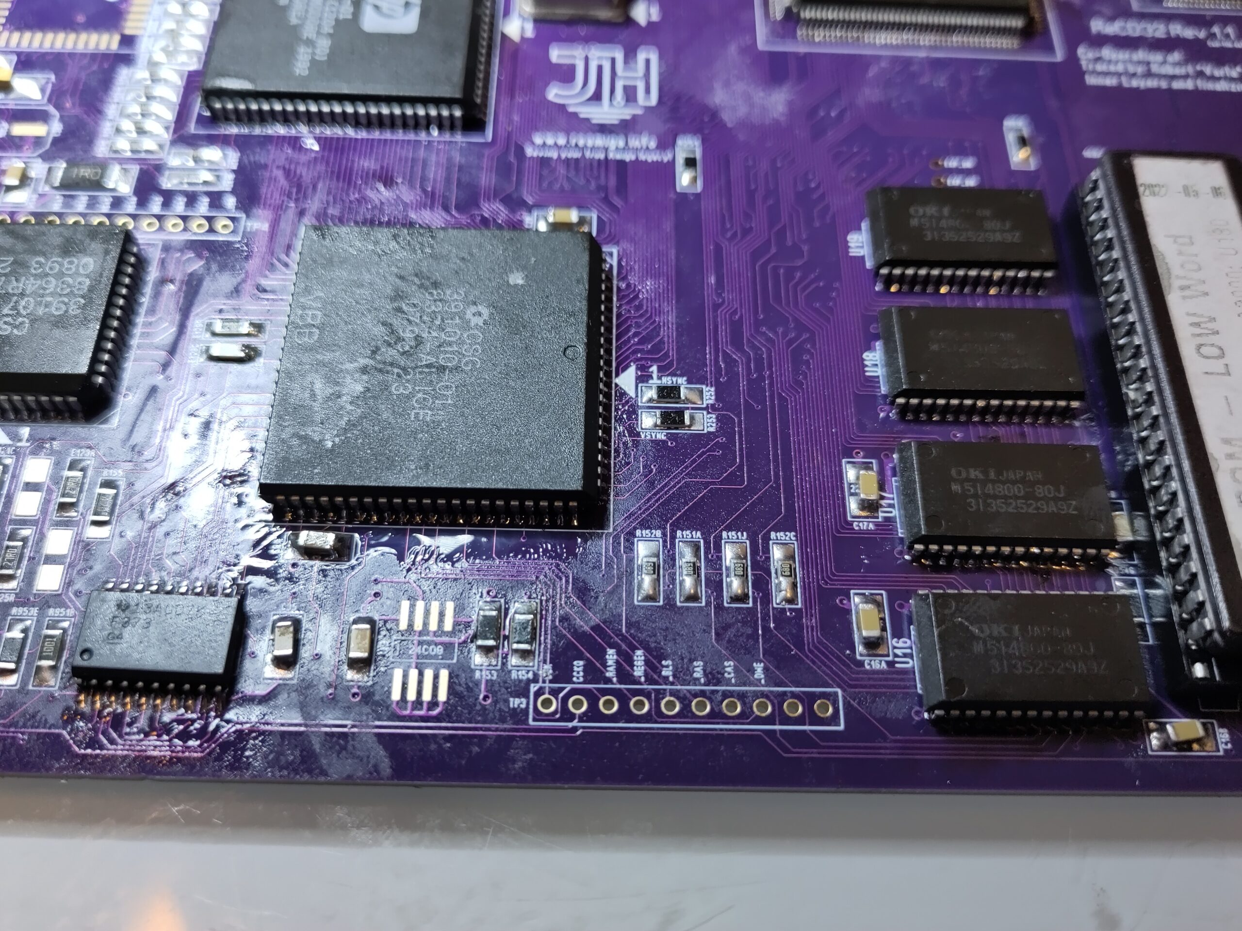
To get RAM working:
Add U35 (74F373)
and the RAM Chips. (every chip is 8 bit if you run diagrom between the chips)
Add the VideoDAC (U30) (ADV101)
D215 (LM386)
U36 (74HC4066)
and now you should get stuff out on the VGA port. (NOTE!! 15KHz).
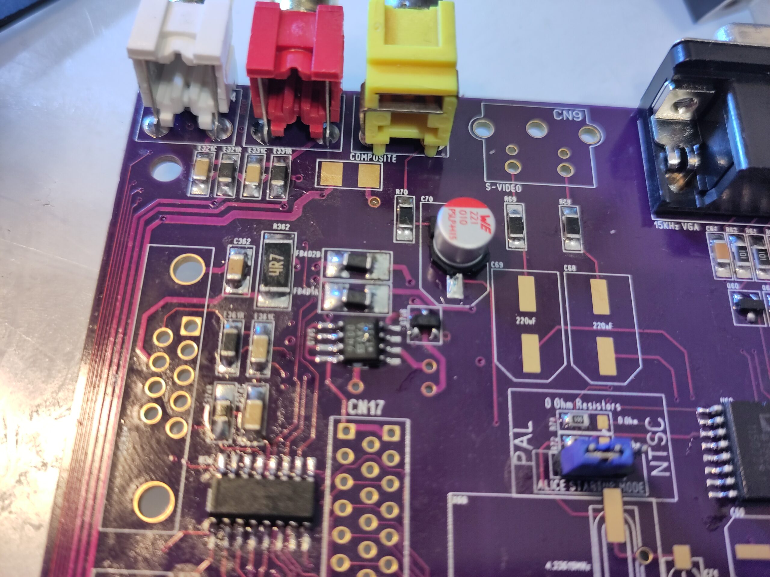
Put in a jumperheader at PAL/NTSC location and put a jumper at desired more (and 0ohm resistors between correct pads). Also add the Composite video connector.
to get picture out you will need one cap as shown. this will give some kind of picture on composite (on PAL most likly black/white to be fixed later)

Now it is time to add stuff for audio, extra videomixing (from FMV card etc):
add:
U15A, U15B, U38B (LF353)
U38A (LM358)
U39 (CXA1553)
U31 (LC78835M)
U22 (74HC4066)
U32 (78L05)
X3 (16MHz)
RCA Plugs for Audio.

On this picture you can see that I put in a 16bit rom. you can still do that even if you soldered stuff for 32bit. you just remove the jumper to the right of the ROM and original 16 bit roms works fine.
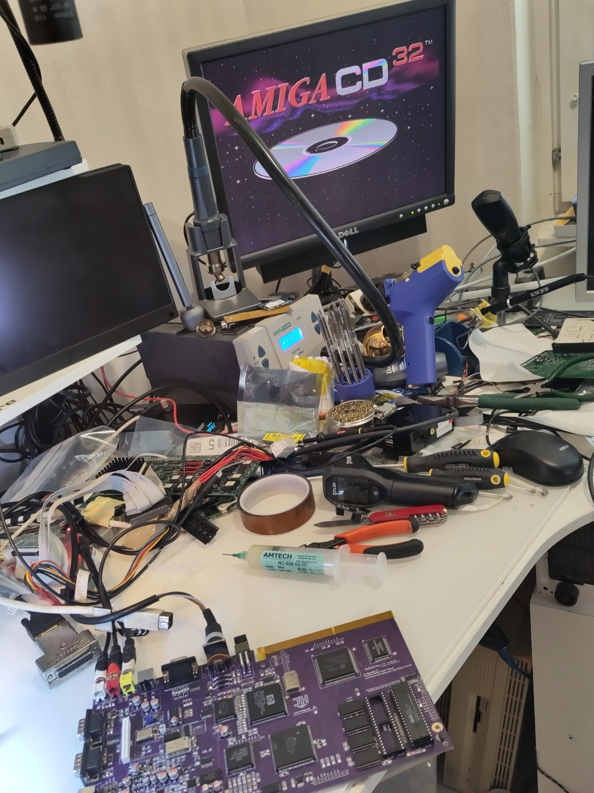
you shold get the famous CD32 animation. (on Composite on PAL will be black and white etc) and no audio yet!.
Lets add the small NVRAM.
Add U9 (24C08)
also on the location marked Q765, schematic say it is a small transistor. so I move that chip that is on the cd32 🙂 )
Also solder in S-Video connector.
and add the Trimcap (I DO recoment putting it AFTER cleaning however)
also add the connector to the CDROM. (there are 2 types on original cd32 etc so this is why the connector is “odd” same on original machine) note rotation of the connector:
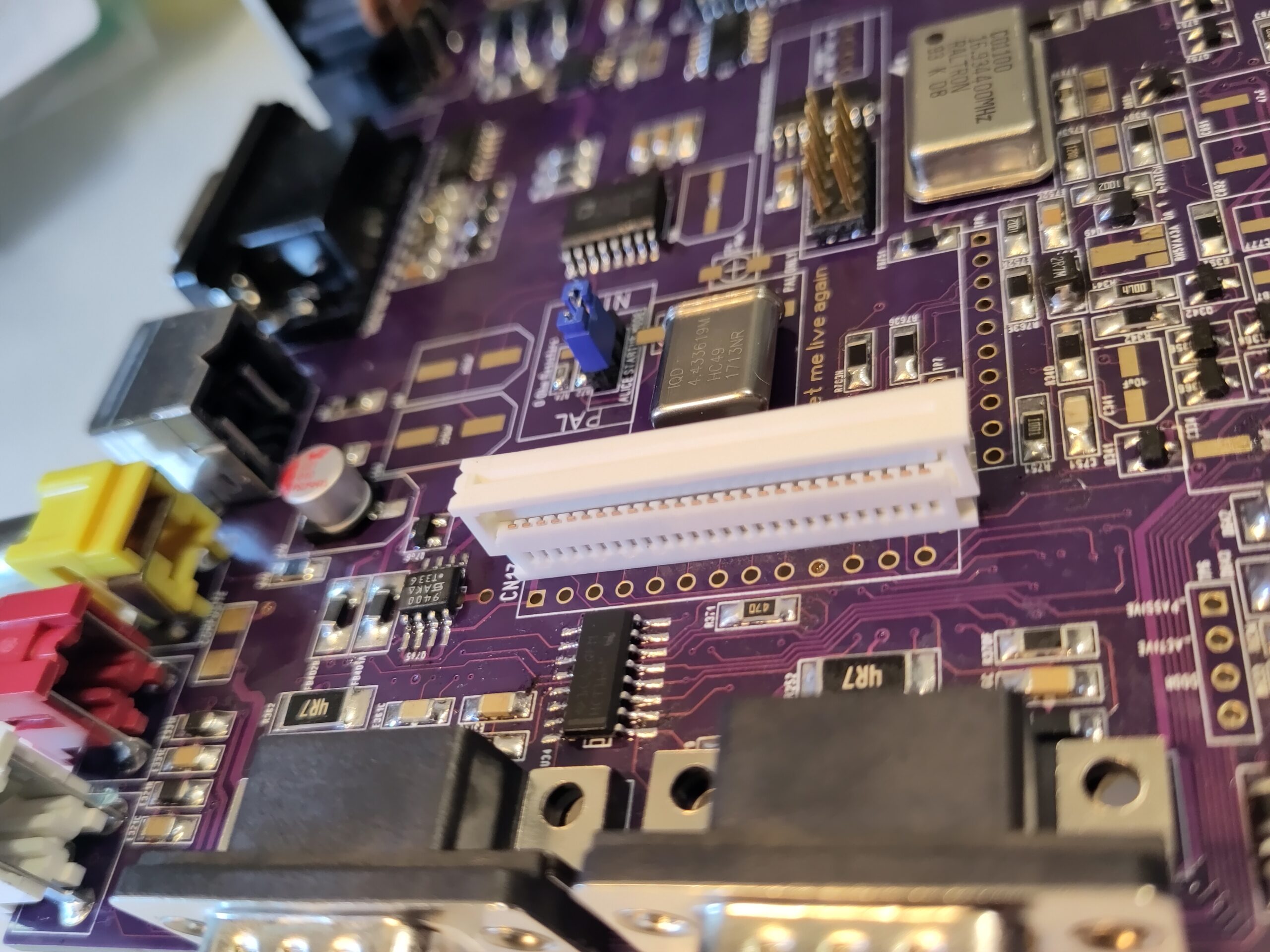
I lifted up the latch here so you can see more easy how it should be rotated.
Now solder in the rest of connectors, DSub, Led board, amd Keyboard.
and after that add your electrolytic capacitors: (and NO! you do NOT use Ceramic or Tantal capacitors they behave different! use high quality electrolytes)
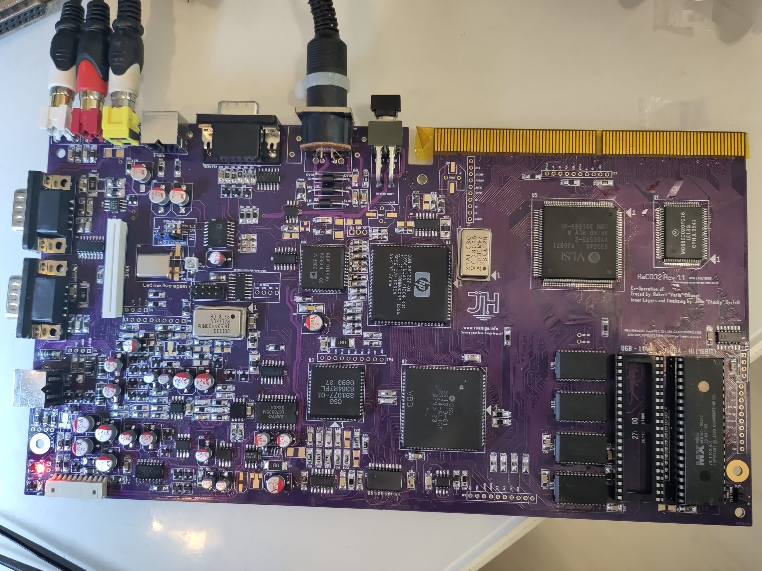
So lets start it up:
you MIGHT need to adjust the trimcapacitor close to the 4MHz oscillator to get proper color output on SVideo/Composite for PAL.
Enjoy!
Hi John,
I have a rare Commodore prototype I think you maybe interested in. If you send me an email; I would be willing to send it to you to reverse engineer.
Sorry to post this in your comments however I cannot find any other way to contact you.
Let me know?
Michael
Good morning
I finished the soldering for your cd32 motherboard.
Before starting, do i need a special version of Diagrom for cd 32?. If not, do i need a diagrom for a1200 or a diagrom for A3000 – A4000
Best regards
Hello
I forget to ask you a question : the cxa1553 component is very hard to find. Can it be replaced with another equivalent component? what is the function? sound? video ? Other function?
Best regards
Hi John,
Will you release the scanned PCB layers that Róbert Tihanyi sanded away? When will you release the gerber and Sprint Layout files? Thanks in advance.
Best regards,
Kerim
It is up to Róbert when it will be released
Hi John,
Could you ask Róbert when he will release all the files? I’ve tried to contact him with Facebook messenger, but he still didn’t reply even after 10 weeks…
Thanks for sharing the gerbers, John! It’s at:
https://www.reamiga.info/webfiles/ReCD32/
Hi John,
thank you for the amazing ReCD32 project! Are you going to make some modifications to your motherboard please? I know that most of them are not easy.
For expample there could be:
-Sega Mega Drive/Genesis 9 pin mini DIN AV connector for RGB instead of the S-VIDEO
-HDMI output with raw digital data output for Morph 4k or RetroTINK-4K
-USB ports instead of DB-9 or bet with integrated mouSTer instead of them right away. So everybody can use a modern USB mouse or a gamepad.
-or PS/2 instead of the AUX for the keyboard by this of this project. That guy comes from my country. So maybe I could contact him to help with and the integration into the new board revision or so.
https://www.amibay.com/threads/amiga-ps2-keyboard-minimalistic-cable-adapter.98464/
Or making it as an ATX motherboard for PC case would be nice. There should be released the Felix’s ODE called Phøde for CD32 soon…
Thank you.
As this is done via Sprint layout hard modifications is nearly impossible..
What I will do in the future of other projects. we will see
Silly question, probably, but do you or anyone else know enough about the CD interface to know if we can swap out other CD drives or controllers into a custom CD32, or is the original mechanism + control PCB still required?
not what i know of
What’s the name and model of the scanner you or Róbert used to scan the CD32 PCB?
Hi John,
I’m preparing to order the ReCD32 PCBs from JLCPCB and wanted to make sure I select the correct manufacturing options to match your high standards.
Beyond the standard 4-layer requirement, are there specific options you recommend for this particular board? Specifically:
– Surface Finish: Do you recommend ENIG for the AGA chips, or is HASL-Lead-Free sufficient?
– Copper Weight: Should I stick with 1 oz or is 2 oz preferred for the power rails?
– Via Covering: Do you have a preference between Tented, Plugged, or Epoxy Filled vias for this design?
Thank you for all the incredible work you do for the Amiga community!
Best regards,
Kerim