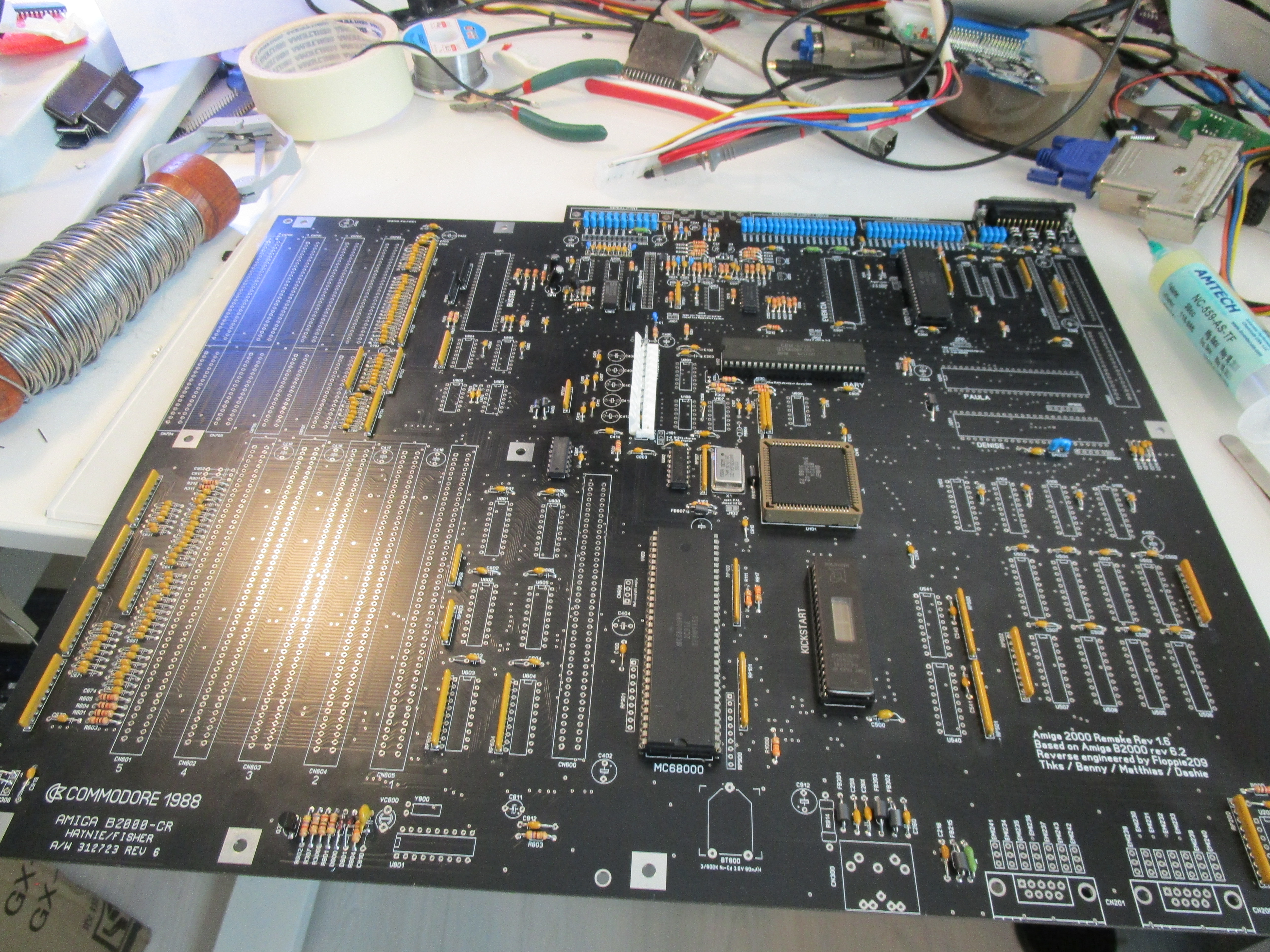
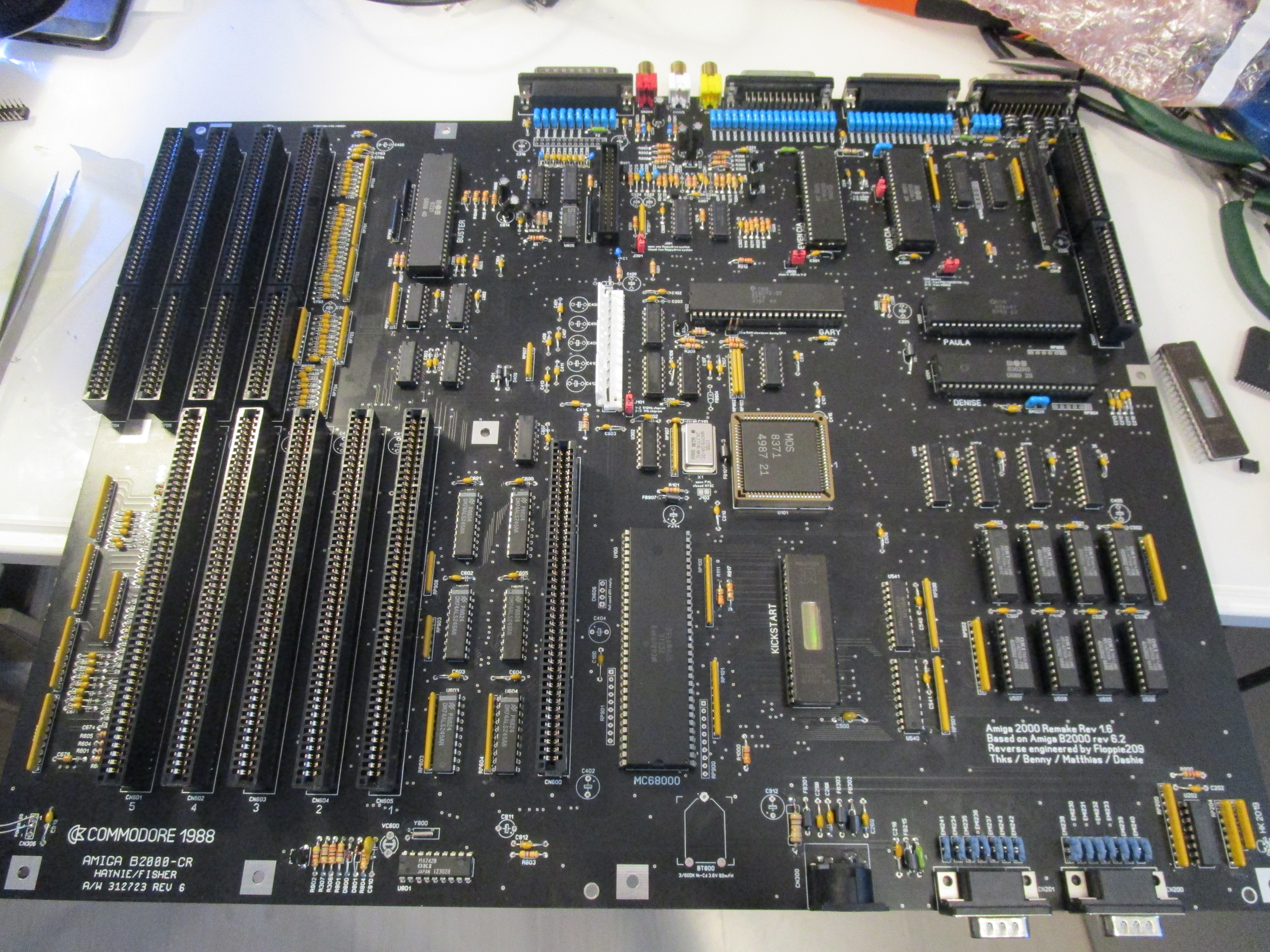
This is a guide how to build the Amiga 2000 Replica.
(not not real “ReAmiga” even if some says so…)
Locator available at: http://locator.reamiga.info/locator.php?project=A2000
Projectpage: https://github.com/Floppie209/Amiga2000-remake (NOPE this is not mine as it is not my project!)
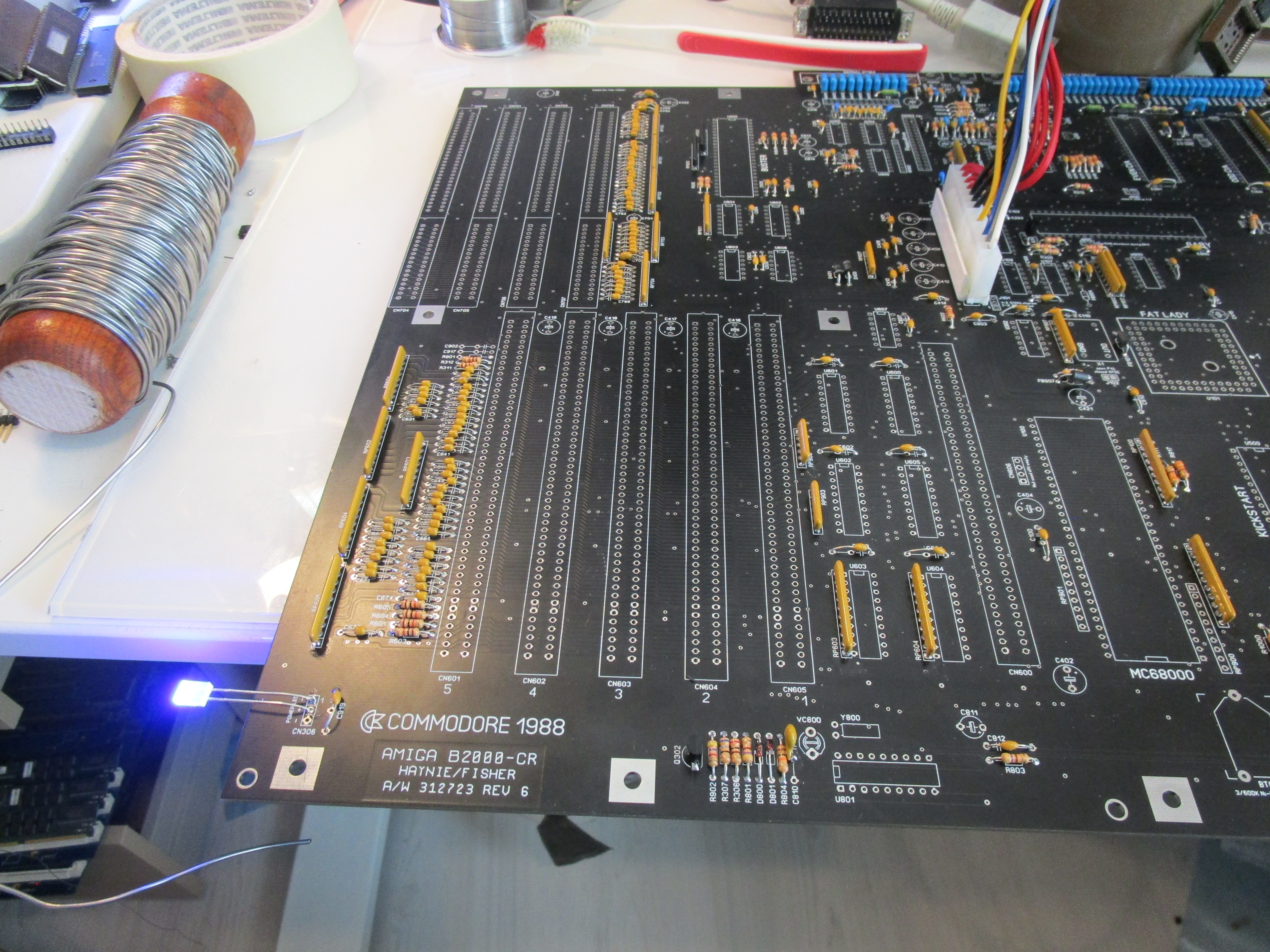
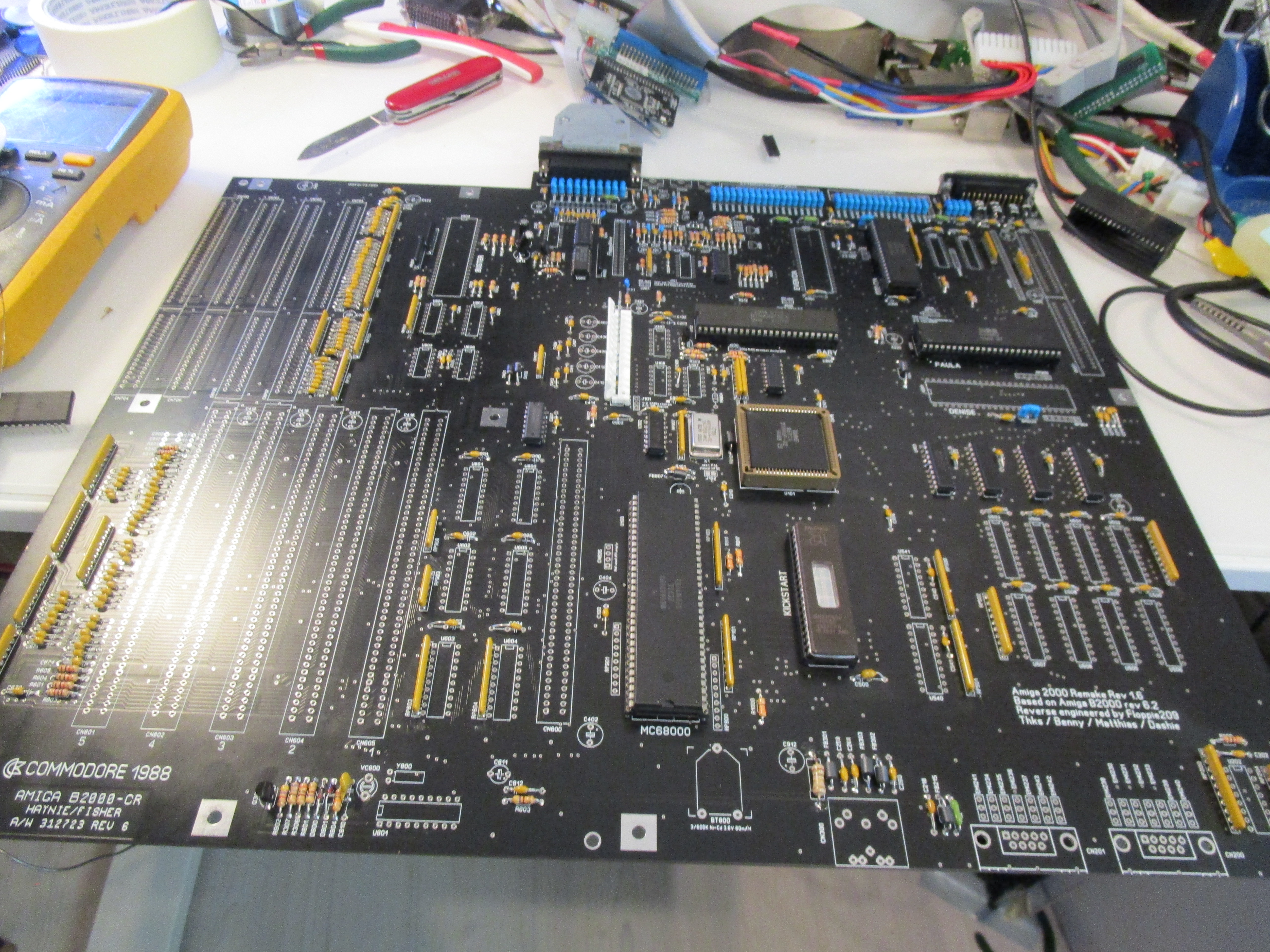
First as usual, I put on all passives: (and as usual I put in the electrolytes in the end!)

then as we all know by now: the powerled is an extremly important part of troubleshooting the amiga.
I actually temporary solder in a led:
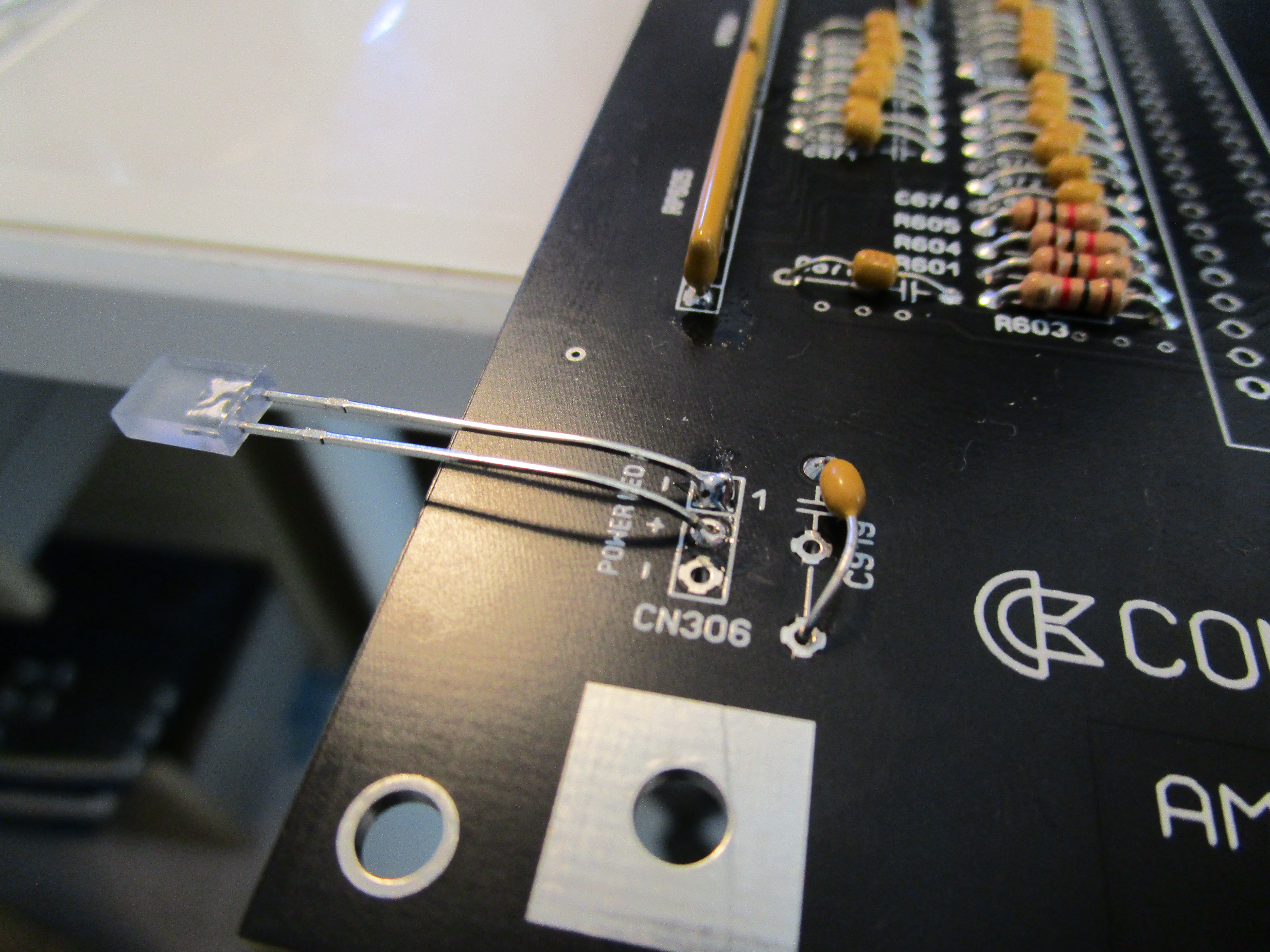
Now add powerconnector and power on:
Now if this is so important? why? as it is bright aleady? well it will get BRIGHTER and that is the key issue! (thats why troubleshootingposts and people say: powerled is on, doesnt say shit! it is the BRIGHTNESS that says stuff)
anyway lets go on. next part is to get the RESET to work:
so I add U805 (LM339), C814, C813 (22uF Capacitors), U607 (74LS08), U303 (74F08)
and XU1 needs to be here aswell.
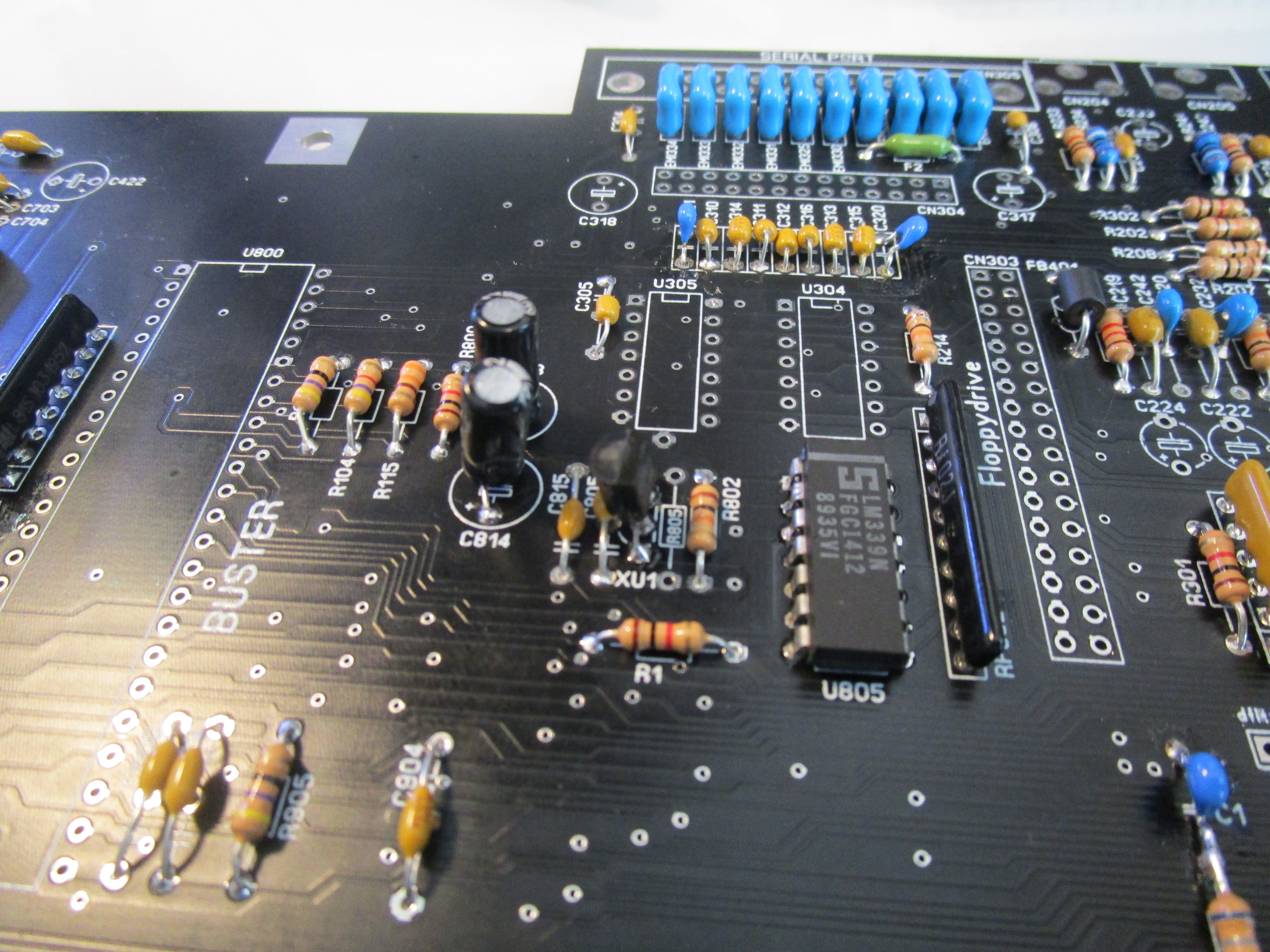
Now we have a working Reset.
Next part is to get a sync from the videooutput:
Install the 23Pin DSUB for Videoout, 28MHz oscillator, Gary and Agnus.
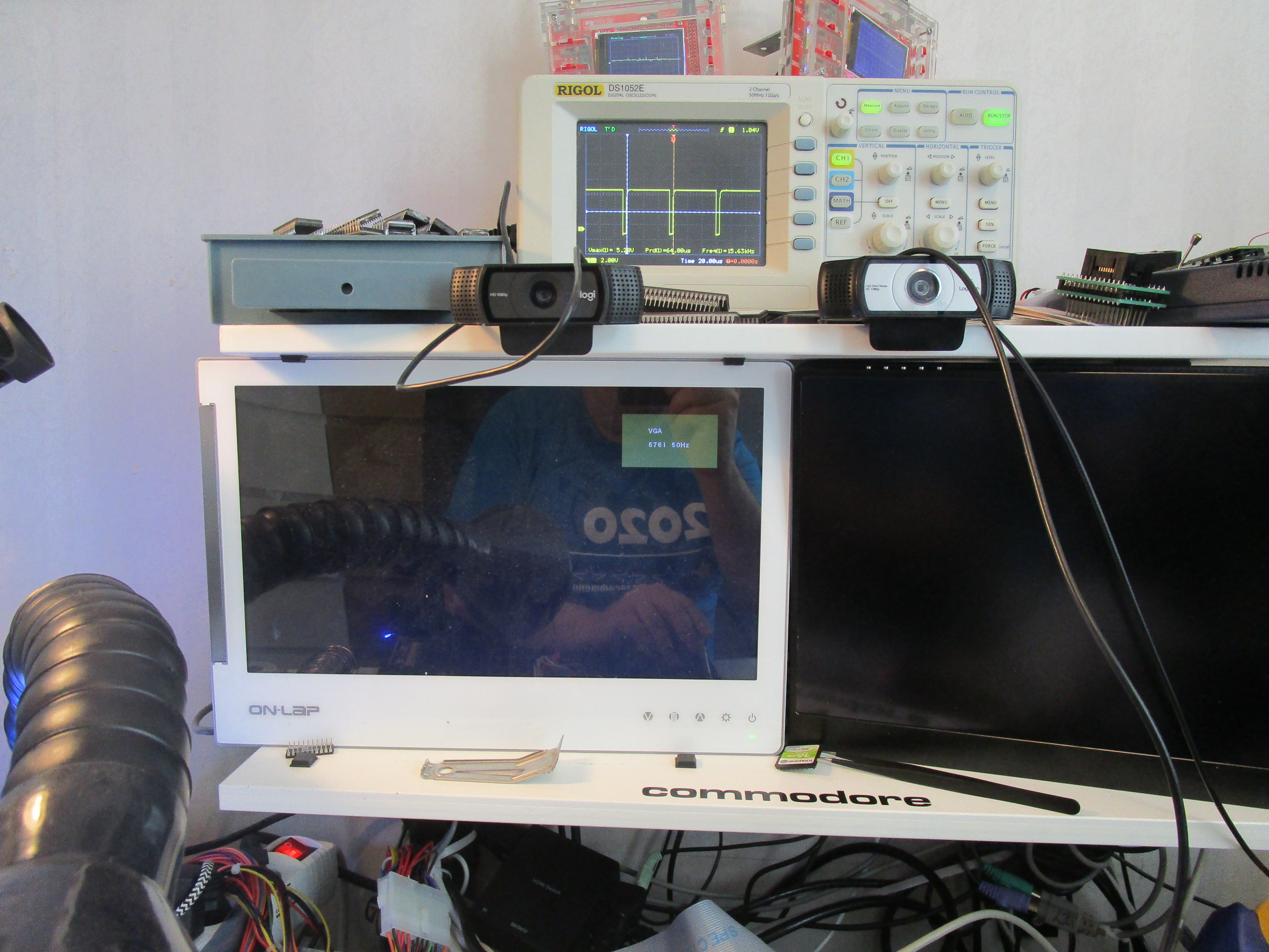
here you can see my monitor gives a VGA splash. (not all monitors does some just give a dark grey screen) and you can also see my oscilloscope shows a H-Sync signal.
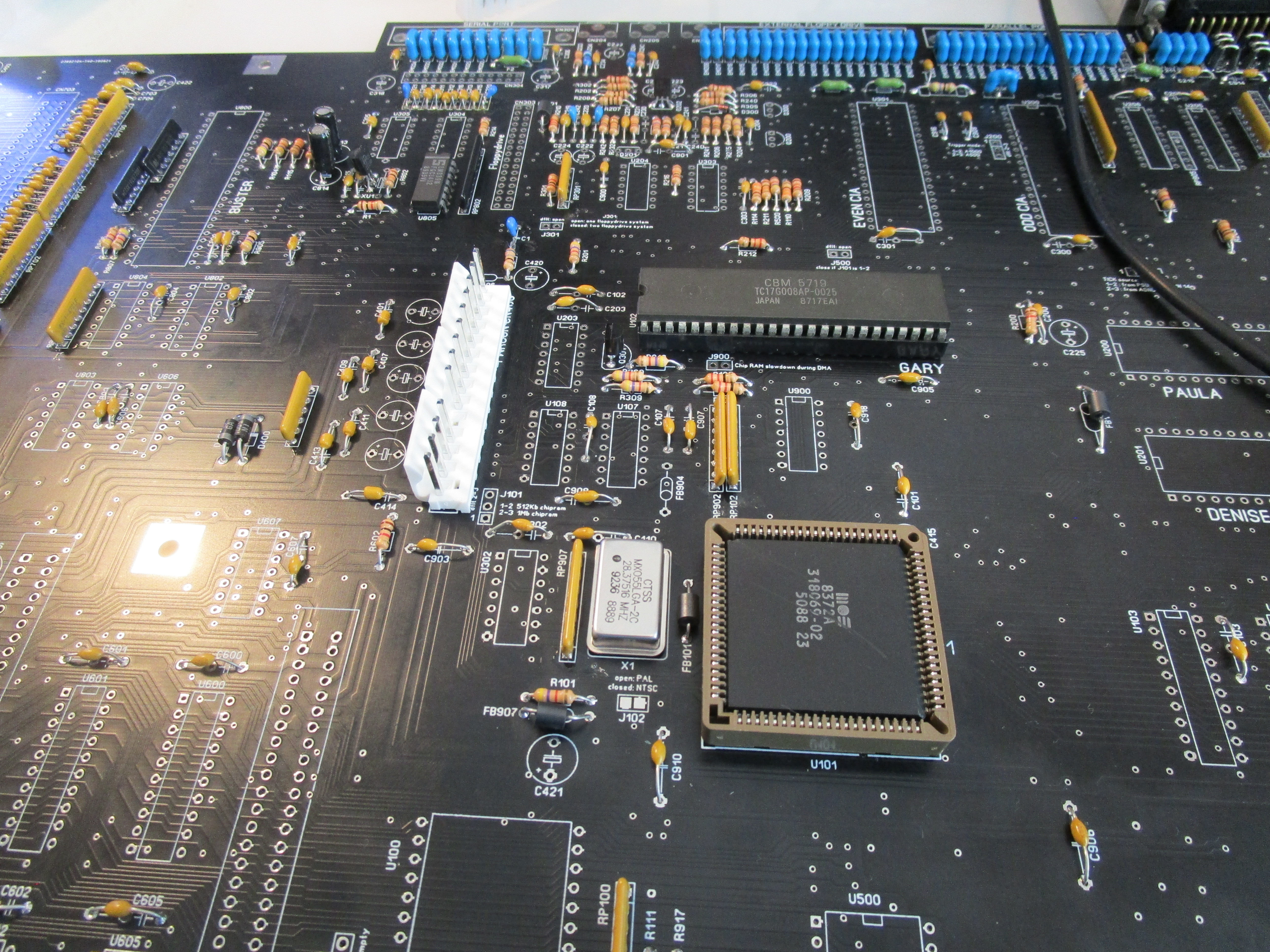
now to get the machine to start DiagROM (I always build using it)
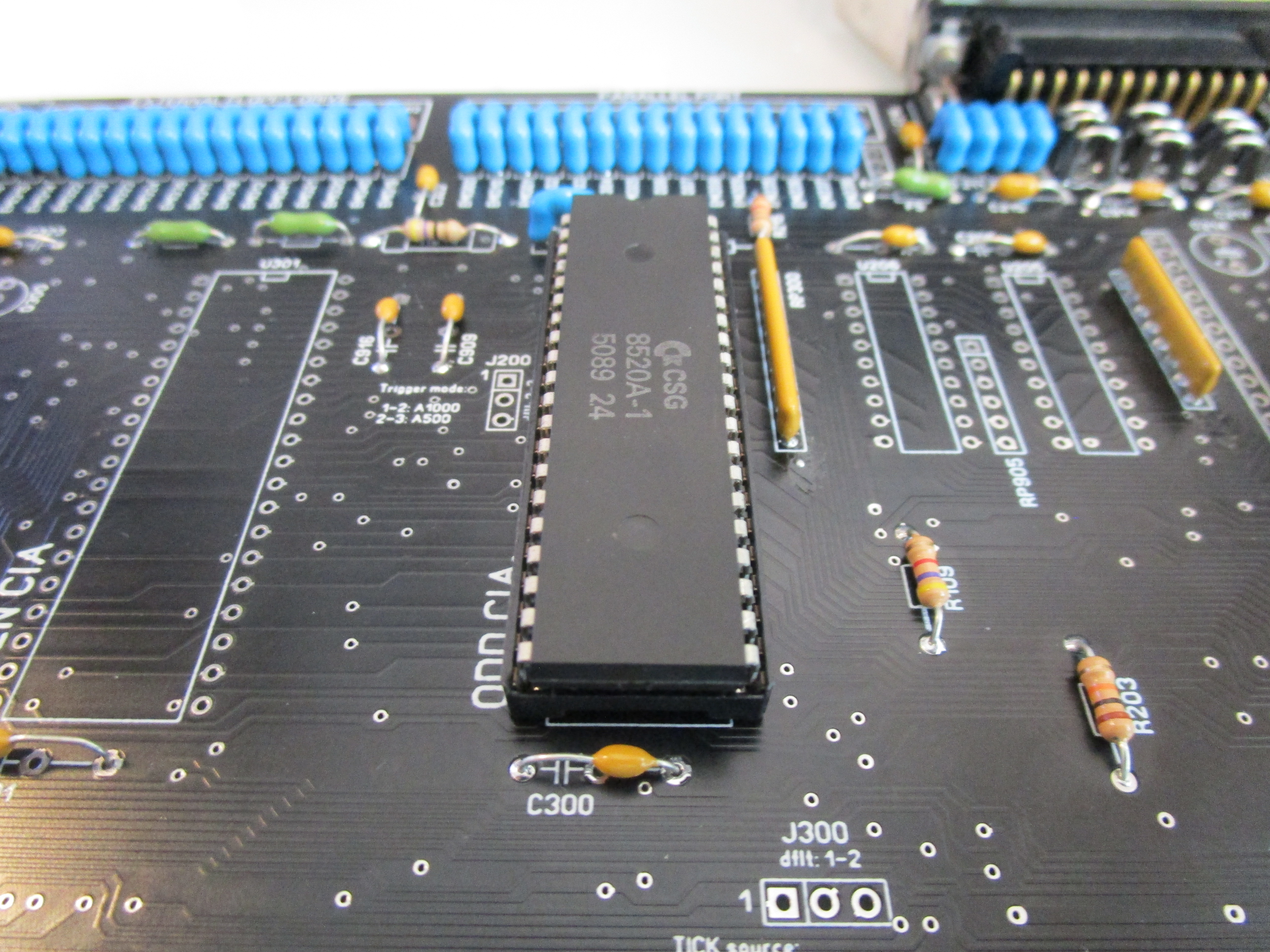
Add ODD CIA (U300)
also add U302 (74LS32), U500 (With DiagROM) amd the CPU:
If you poweron now. after 1-2 seconds the powerled should flash! (YOU SEE!? NOW you notice why it is important! code runs and can talk to the CIA etc)
Now lets add stuff so DiagROM can putput data on serialport:
Add PAULA, U900 (74LS00), U103, U105 (72F245), U104, U106 (72LS373)
U304 (1488), Seriaport connector.
Now DiagROM will output serial data:
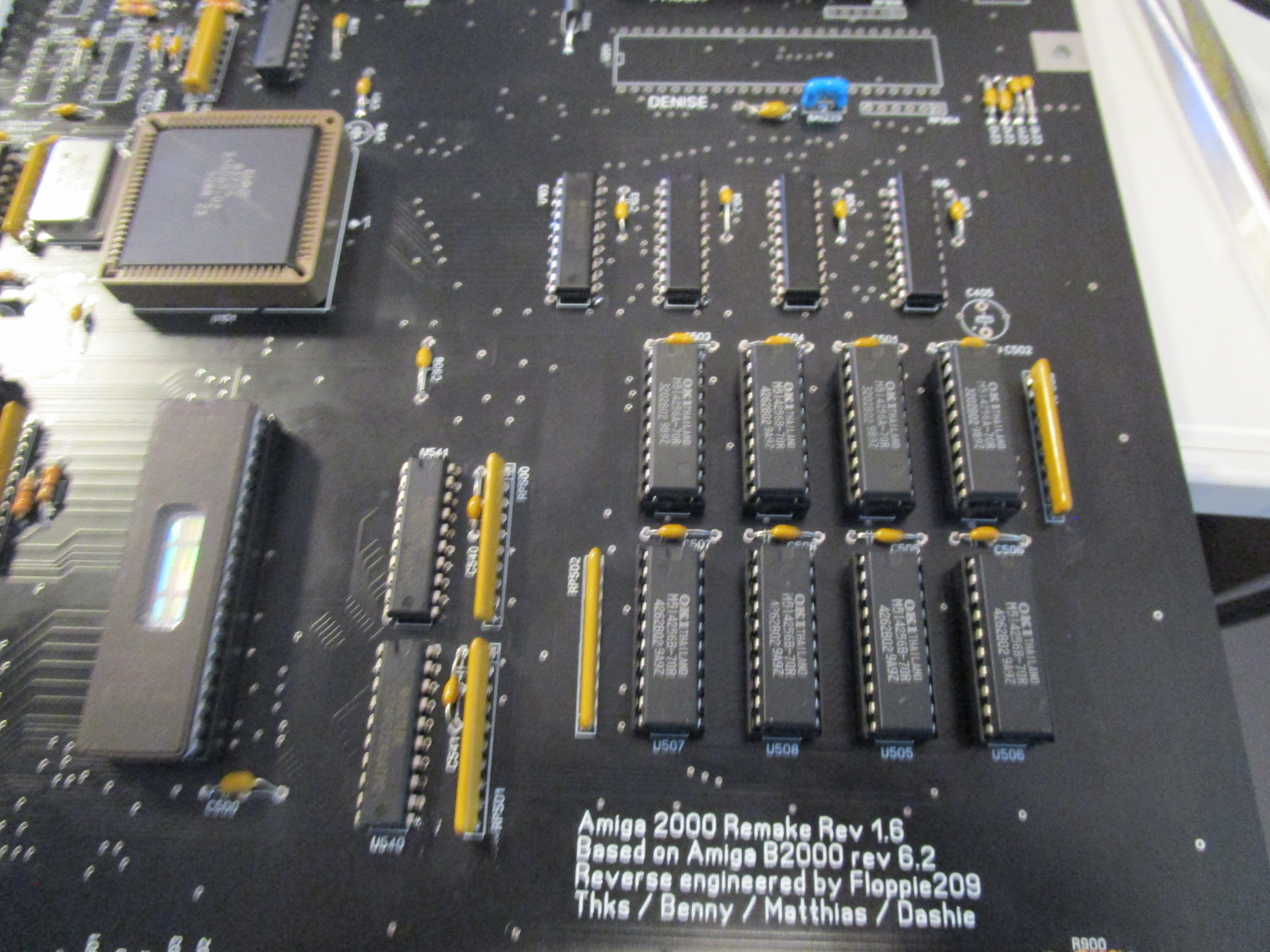
Now for Chipmem:
Add U540, U541 (74F244) and chipmem chips (I recomend sockets for memchips)
Also make sure you have the jumper correct:
J101 set to 1-2 for 512K chip and 2-3 to 1MB chip. REMEMBER that J500 must be also set correctmeaning if this is set to 1-2 for512K chip, close J500, if set to 1MB, J500 must be NOT-CLOSED!
So here is a list of jumpersettings: (1MB Chip, PAL)
J101 – 2-3
J500 – OPEN
J301 – OPEN (no DF1)
J300 – 1-2 (IF you are using ATX PSU set to 2-3)
J200 – 2-3
J900 – CLOSED
J102 – OPEN
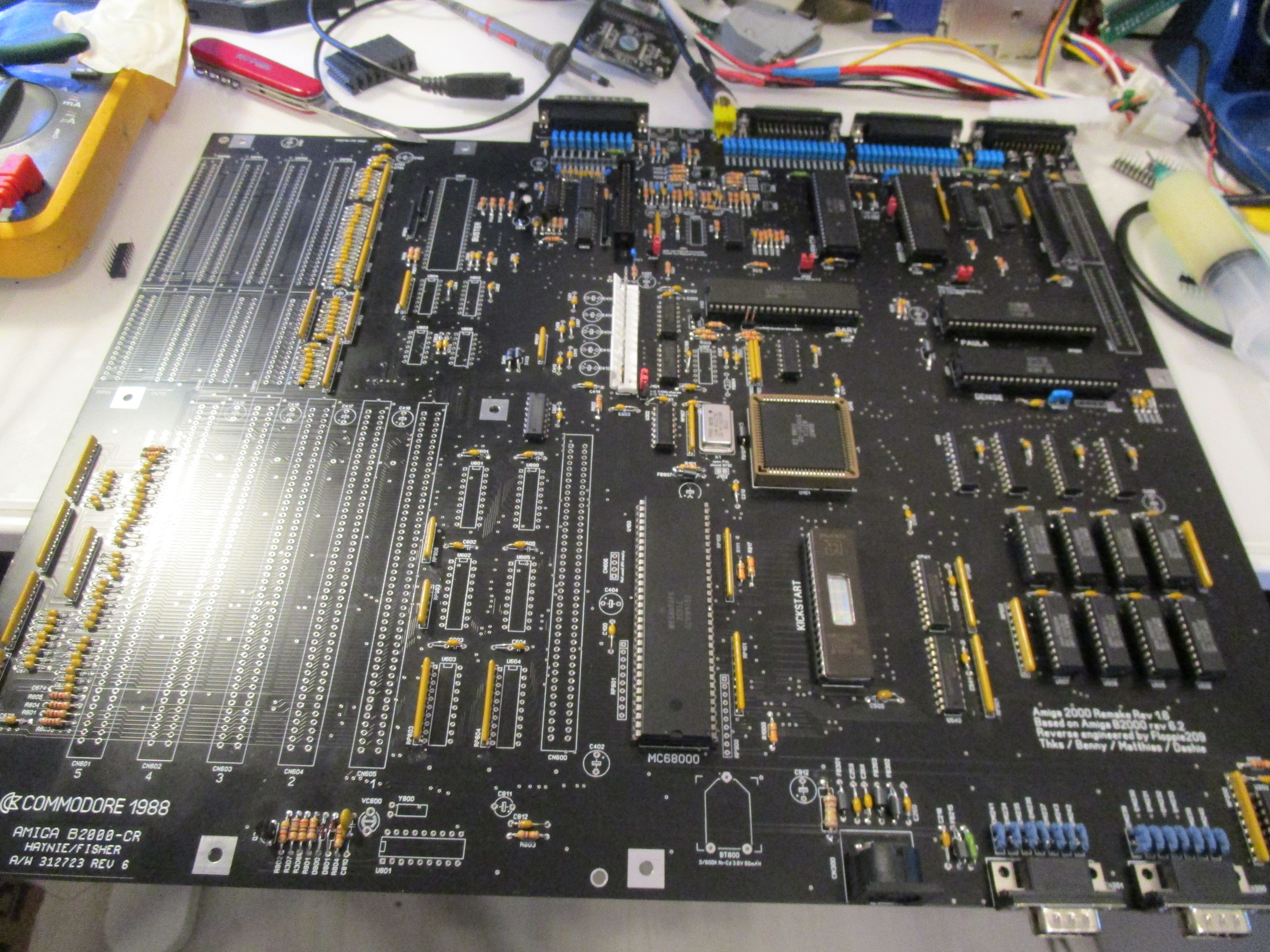
Anyway memory installed:
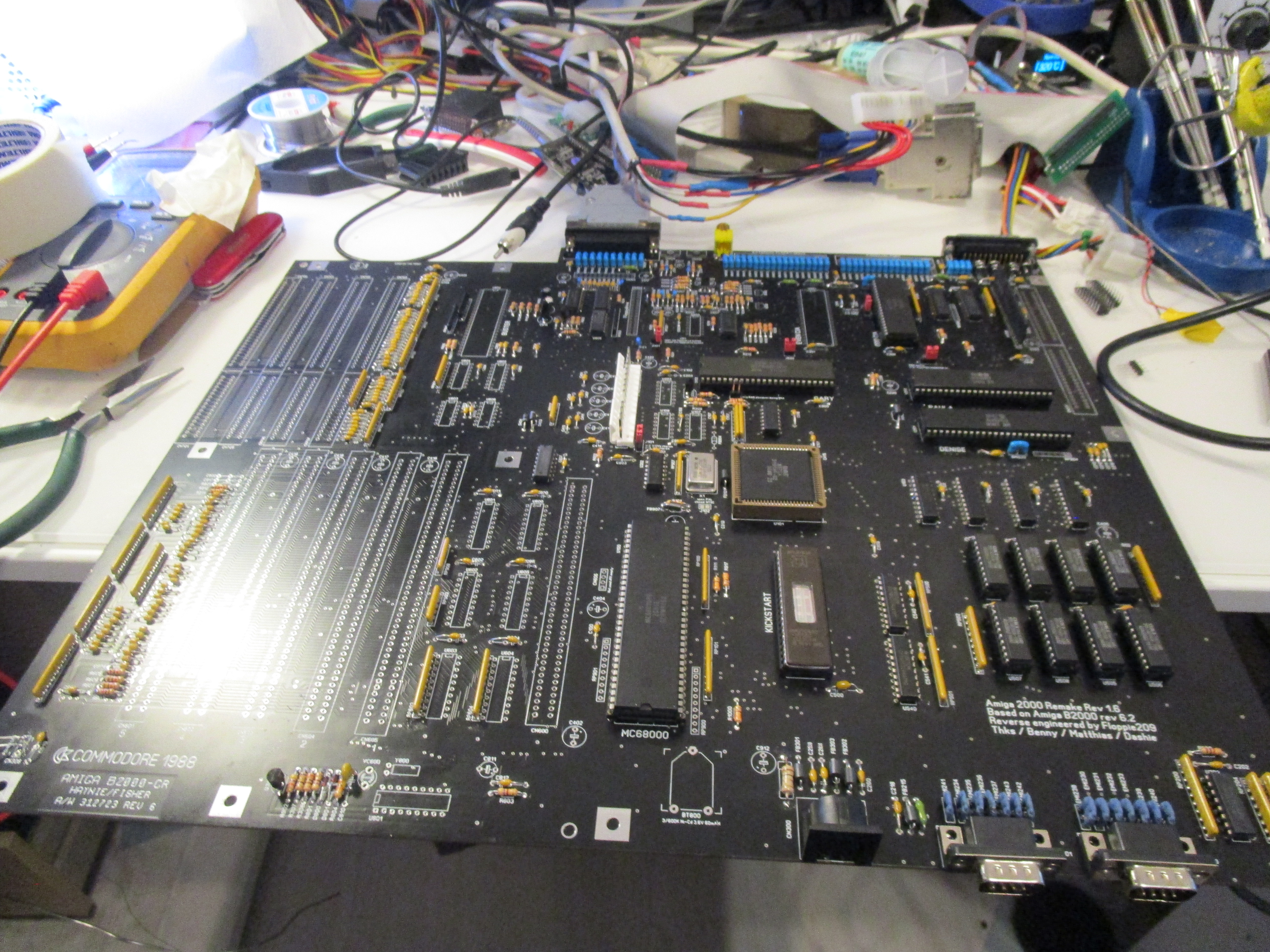
Time to get a picture:
add CN206 (Yellow RCA) (for Black/White composite out)
U205, U206 (74HCT244)
Denise
Videot (text facing into board)
Now you should have video output.
to be able to control the machine add Gameports, Keyboardconnector, U305 (1489) (to get serial in to work) and U202 (72LS157)
here I have been bad and forgot to take photos.. sorry for that.
now get floppy up:
Add EVEN CIA (U301), U108 (74LS74), U203 (74LS38), Floppy connector, 23Pin DSub for external floppy
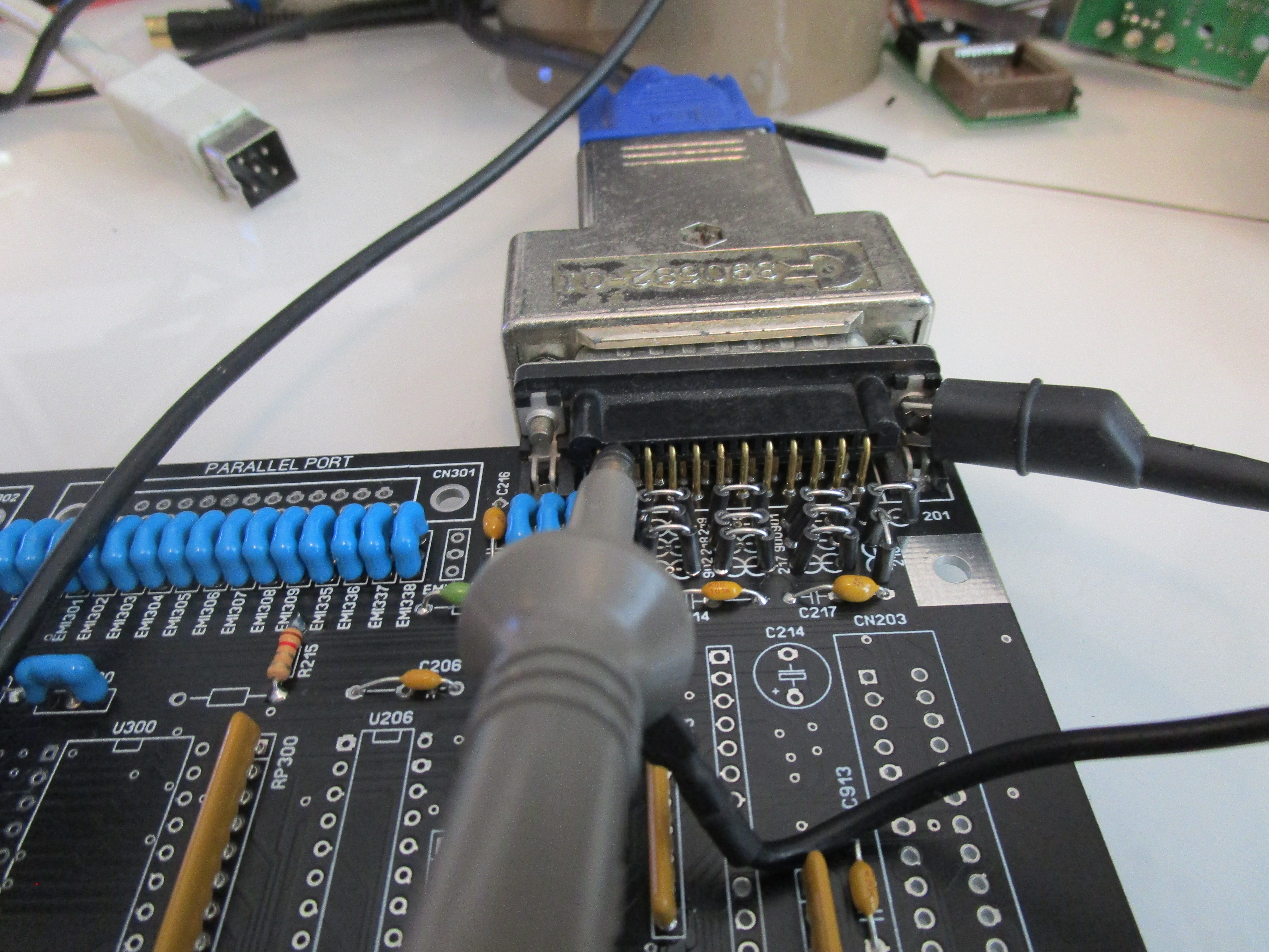
also add Parallelport.
time for audio:
U204 (LF347), C243, C233 (22uF)
now time to get IRQ to work:
U802 (74LS138), U803 (74LS08). U704 (74LS148)
<at this point kickstart should work>
time to get zorroslots up:
U600-U605 (74LS245)
U606 (74LS32)
Buster
and add Zorroslots.
the slots I got had too long pins so I had to trim them:
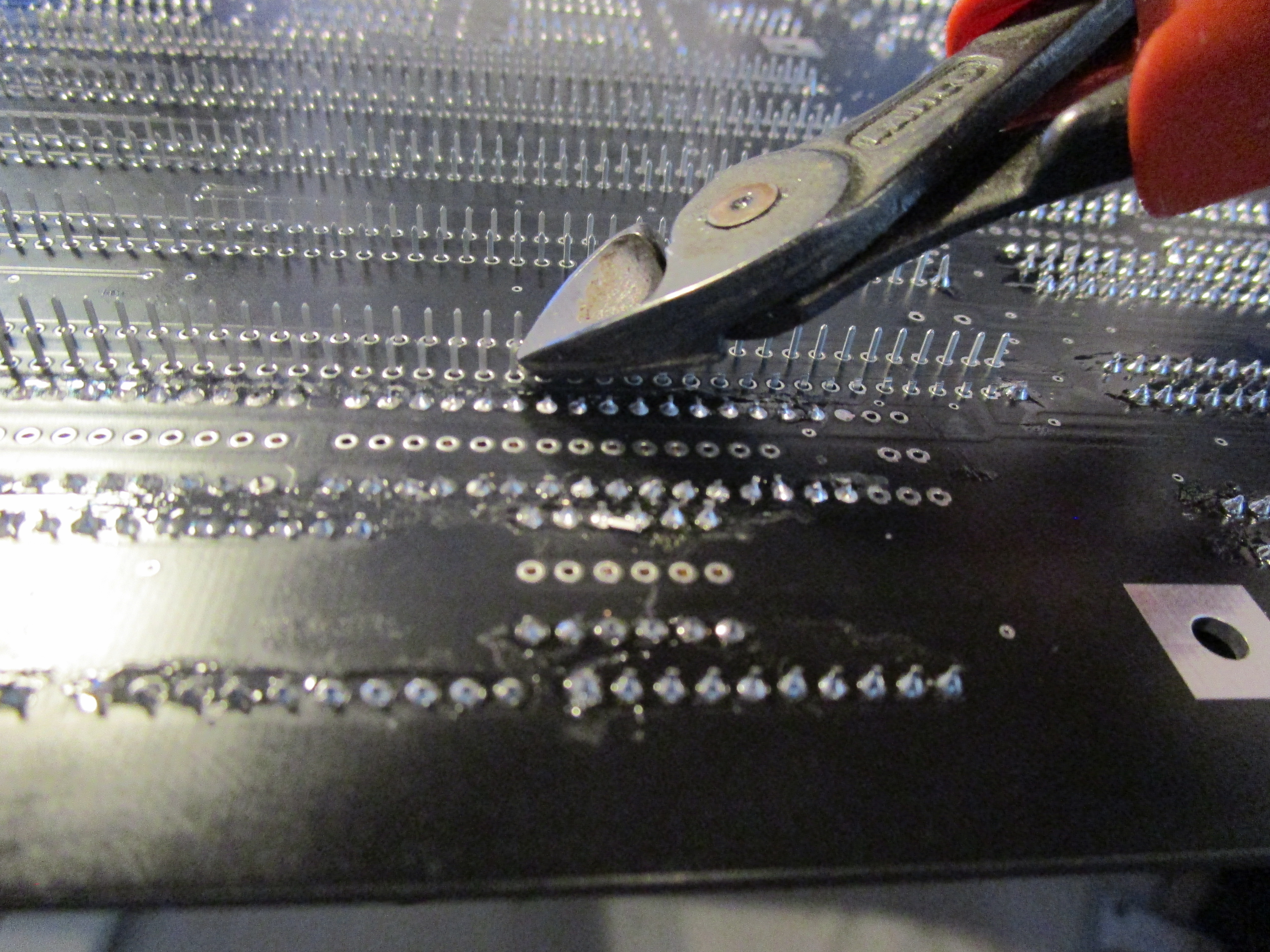
So I simply put a solderblob on each end of the connector to make it aligned, trim the pins and THEN solder on the rest:

So do this for all connectors:
Just add U107 (74F04) and videoslot connector.
and finally U801 (RTC), Y800 (32768Hz) and VC800
someday I will do a post how to trim the cap for RTC on Amigas. some other day. generally around 22pF is a “ok” value for the trim-cap..
Put on all electrolytes etc. all the rest.. and all done!
This is a most excellent walk-thru of the A2000 board assembly. I find the passives to be the most daunting part for me as I was blessed by poor eyesight. I take it that the small components are able to be put on without risk of being on backwards?
Thanx.
the resistorpacks needs to be put in the correct direction. it got a small dot where you should go to pin 1 (square pin)
Hi John!
First to all, CONGRATULATIONS FOR THE GREAT ARTICLE AND AWESOME LOCATOR!!!
I started to solder passives on an “Amiga 2000 Remake REV 1.8.5”, but I have a doubt with the C1 – R2 – FB906 node… What is needed?
On my old and damaged board (REV 6 – PCB ASSY 312720) this zone is empty. The nodes and silkscreen for de FB906 are present but the place is empty. And about the C1 – R2 place, the nodes are there but no components or silkscreen.
C1, R2 and FB906 shares the same node… In not sure about what to do…The place must to be leaved unpopulated? Can you help me?
Thanks!
I haven’t dig so much into the A2k build so I am not sure about specific components etc.
Hey John
Would you like to share your mouser/rigel etc component list for this project? I have one right now but its a littlebit of a mess.
Kind regards
Sebastian
I do not have one sadly.. and as I do not like throughhole. will not do one more 🙂
Hej Jag köpte en A2000 rev 4 med batteri läckage.
Det saknas en vrid potentiometer CV8XX några centermeter från batteriet har du möjligen information om vad det är så jag kan beställa ny den saknas helt på moderbordet.? Jag hittar inte denna information på internet behöver lite hjälp från en expert.
inte vridkondensator? 0-64pF eller liknande tror jag det är
Hi! Congratulations for the great tutorial!
About the first step, what is the best way to figure out LED brightness? Is there any tip to get sure it is ok?
well if it changes it works 🙂 if not. follow my guide.. 🙂