Next in my series of building Amiga clones.. the Junior 600.
What is the Junior 600? it is a A600 clone made by Róbert Tihanyi.
Locator for this can be found at: https://locator.reamiga.info/locator.php?project=Junior600
As usual we start with a board with all passives installed already. (Resistors, Ceramic capacitors, Diodes, transistors) NOT electrolytics as usual.
AS usual follow this guide! please take as a habit to READ the instruction once first before even starting to do stuff. Actually before ordering components aswell. do NOT ask me “hey this doesn’t work” as if it is not in this description. I will not know anyway (I add stuff here if I find out more stuff) also do NOT ask for help if you build the complete machine and THEN try to poweron…
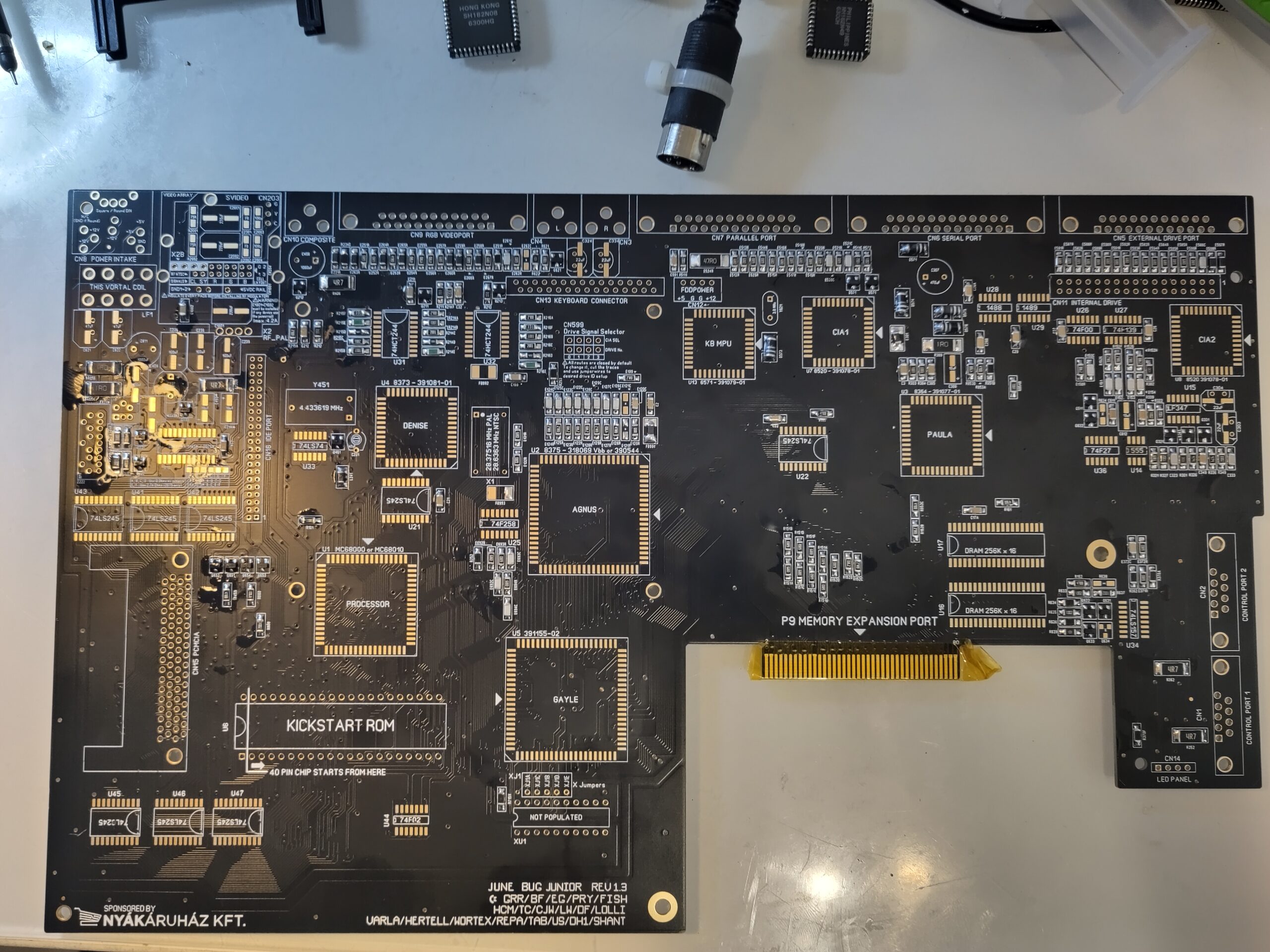
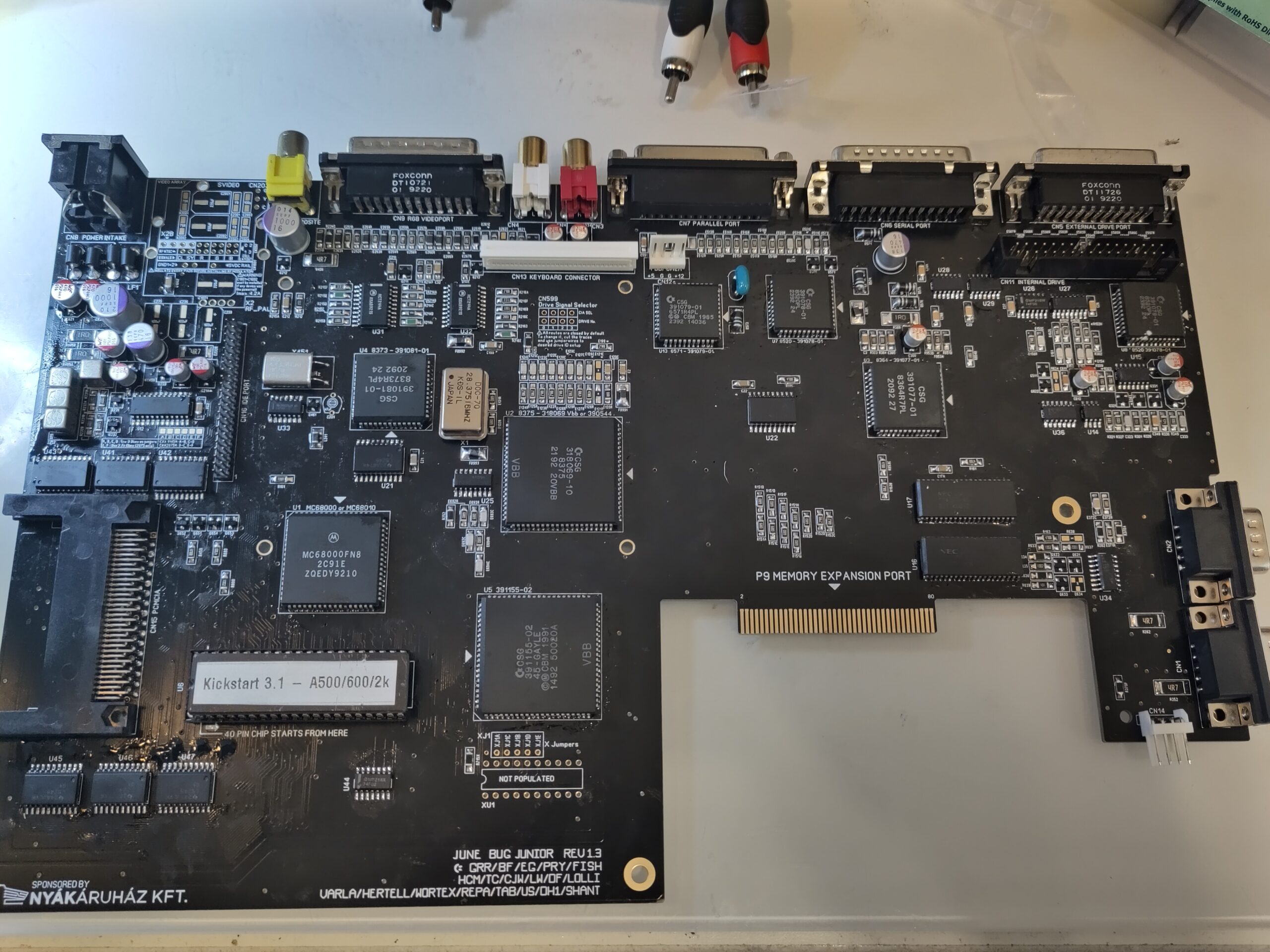
So this is what we have to start with:
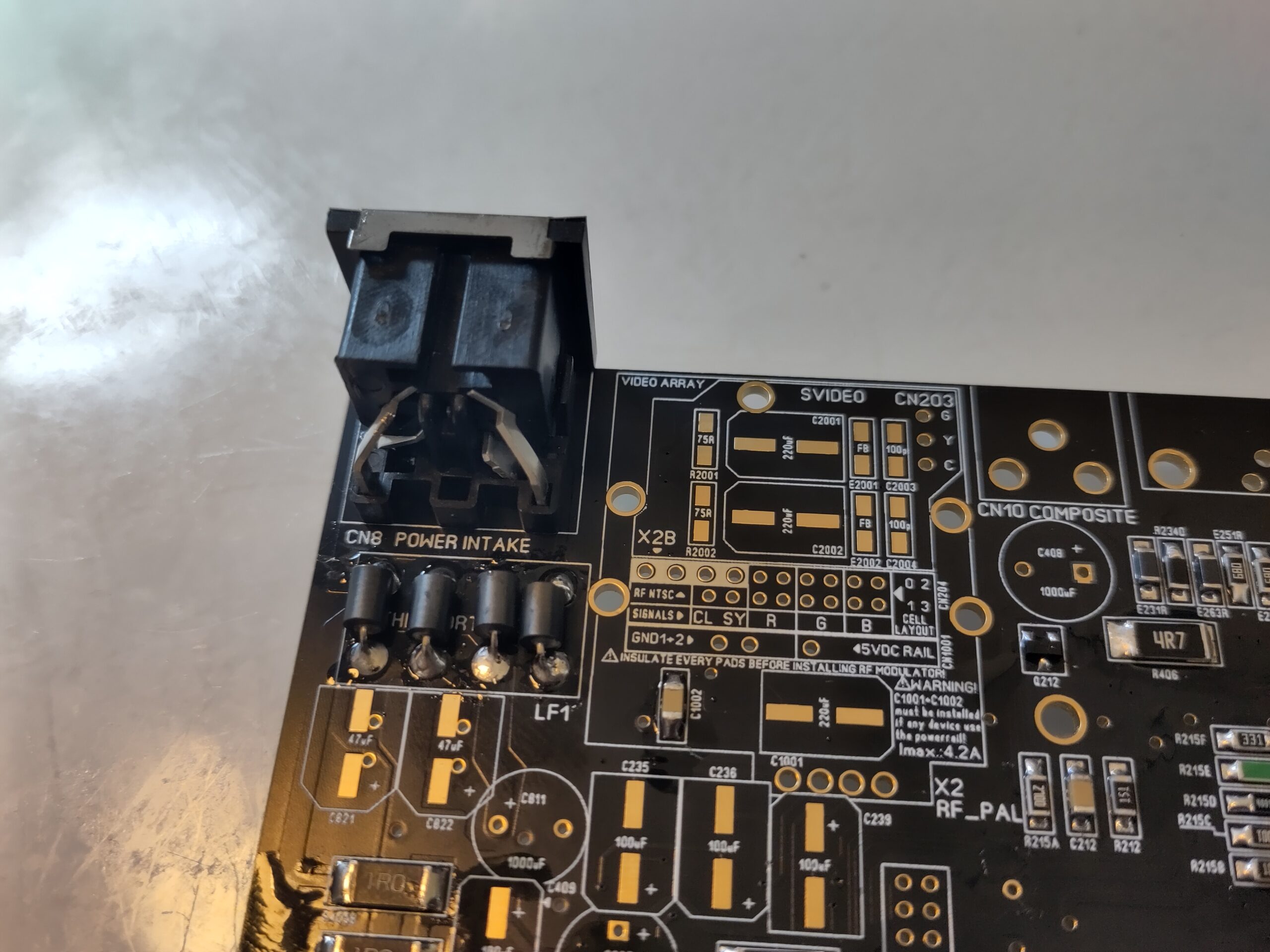
I have put kaptontape on the connector, so if I by misstake drop solder there,. it will not damage the connector. Anyway. lets get power working on the board.
for this you need to solder in the Powerconnector and the filter. I have replaced the original filter with 4 Ferrite Beads here. ALSO I added the ledconnector so we can see that power works.
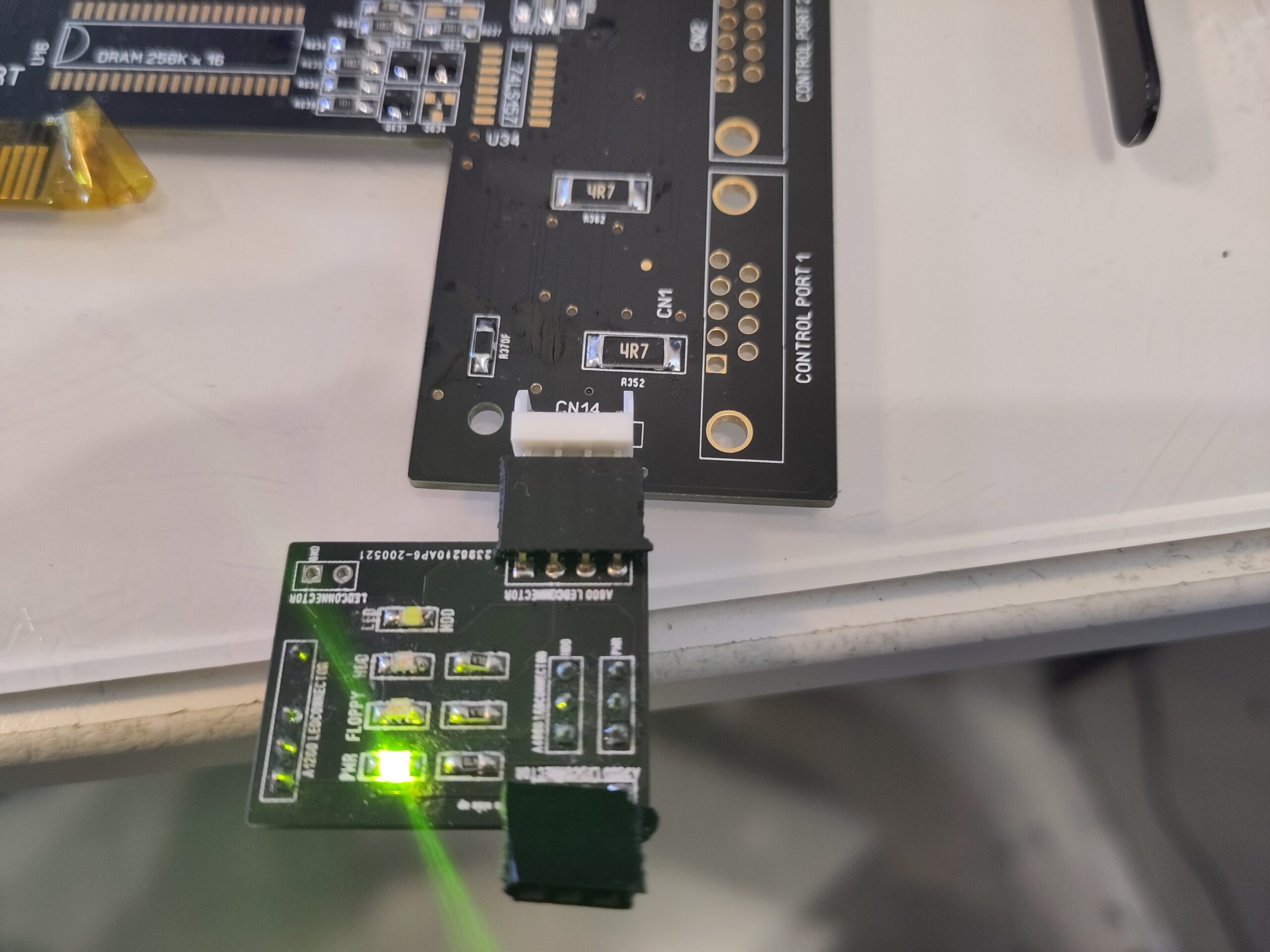
I am using my small test ledboard here. you see. power. (SO this is a proof that “Powerled is on” is NOT a sign of a working machine as we have absolutly NO chip installed) ANYWAY, Next step is to get the Reset to work.
A VERY important note. the Junior supports round powerconnector just as my ReAmiga 1200. IF you have it. there is a ferrritebead you need to place on the underisde of the powerconnector.
IF using the original square one. do NOT populate it! (E999)
This is done by adding U14 (NE555) and U36 (74F27)

So next part is to add the main clock, by adding X1 (28MHz oscillator) and U25 (74F258)
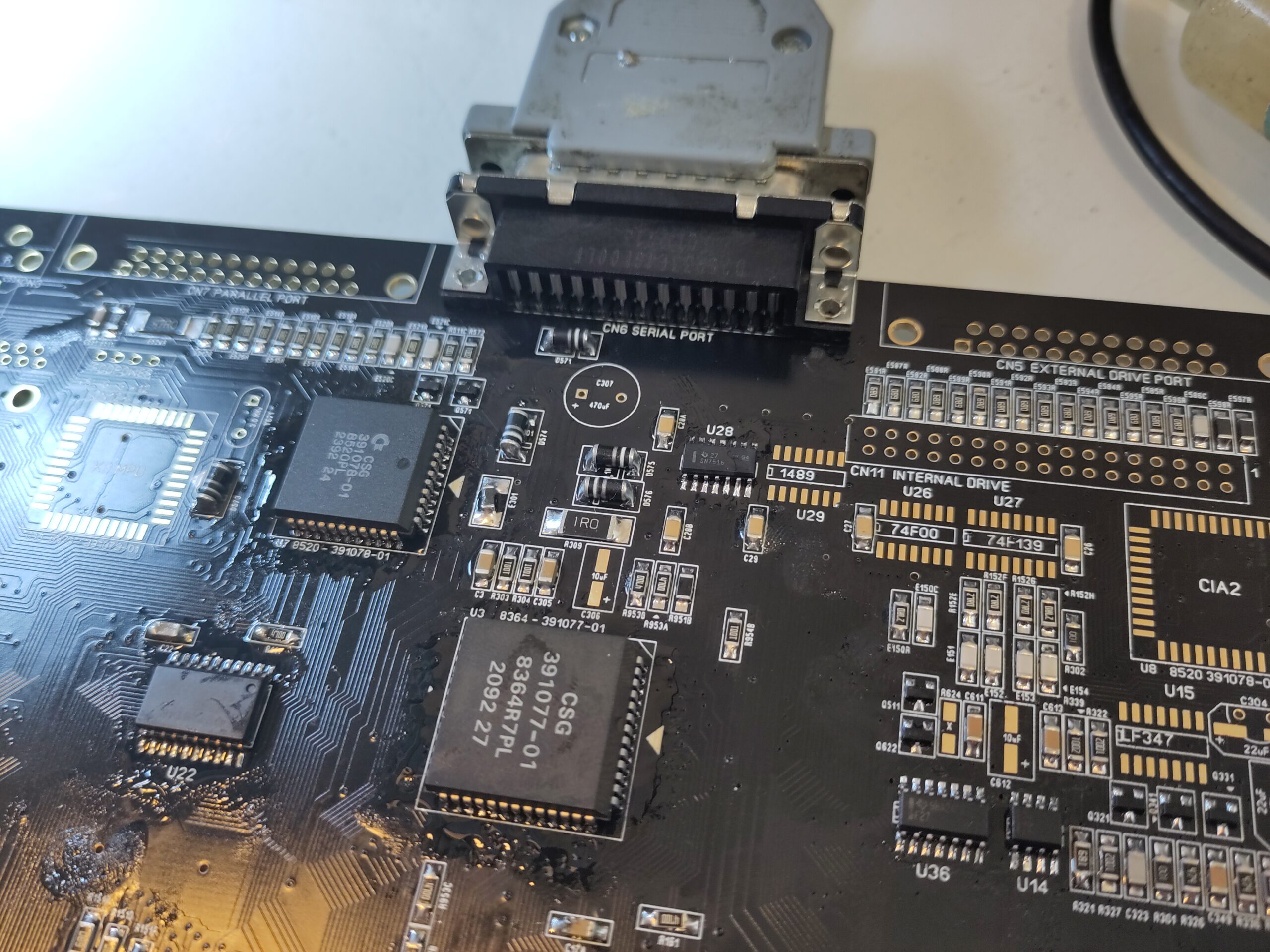
and then we want some activity so first lets get a V and H sync on the RGB port, so we add Agnus, Gayle and the RGB Port.
SADLY I of weird reasons did not take a photo of this config. I however have it on another machine I did, a Red one so lets take that photo instead. (sorry)

Now there should be V and H Sync on the RGB output. Either you check with an oscilloscope or as I can, plug in my monitor and you see it goes out of powersleep mode.
Anyway. time to run some code..
Lets add the CPU, ROM (Put in DiagROM), U7 (8520), U21 and U22 (74LS245)
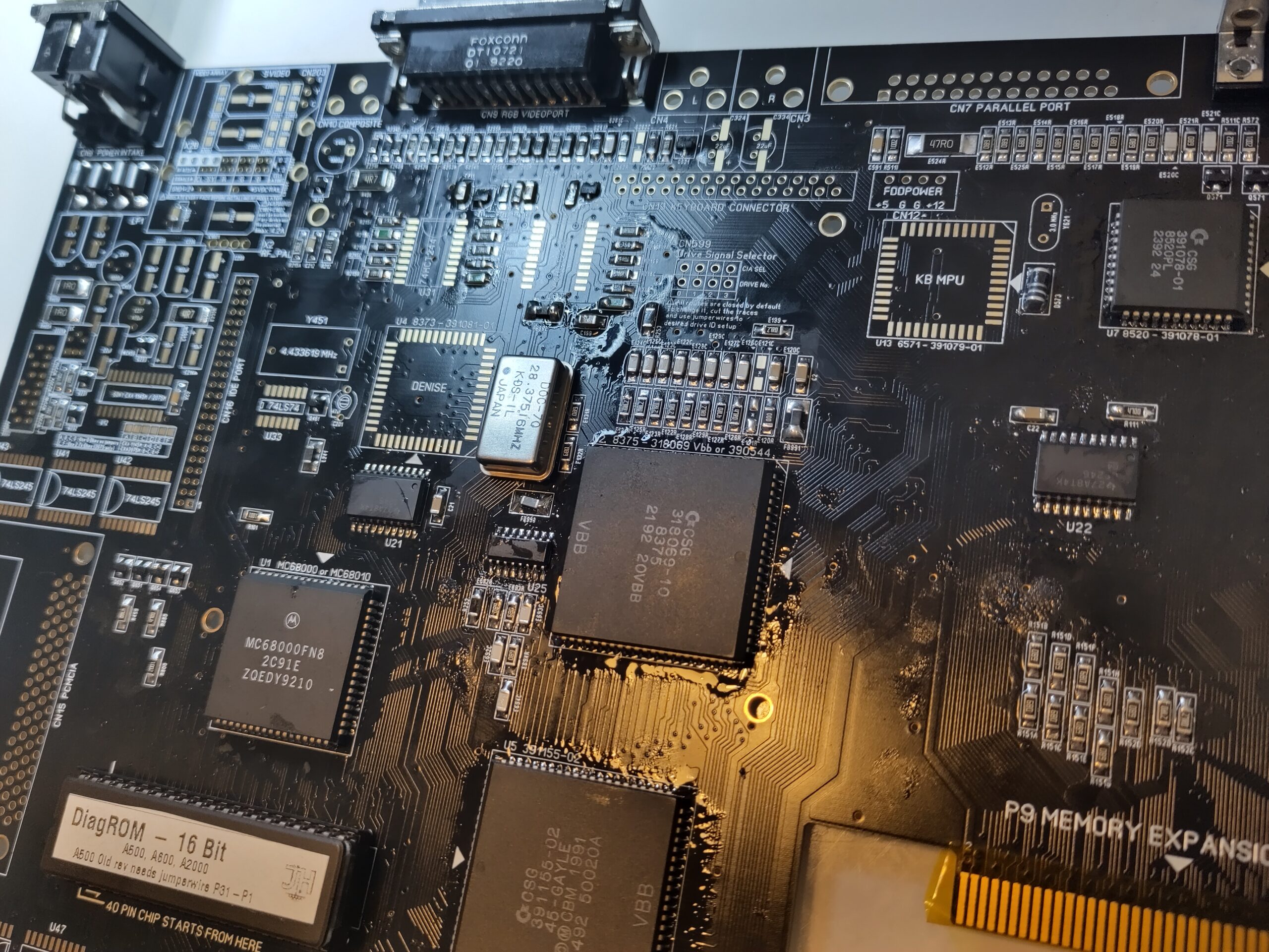
When you poweron you should see that the powerled will flash some (or atleast change brightness)
so time to get stuff out on the serialport via DiagROM.
Add Paula, U28 (1488) and Serialport.
Now you should get text out from the serialport from DiagROM.
Time to get Chipram working.
Add U26 (74F00) and U27 (74F139 or 74ATC139)
and I add rams in the order of first U17 and then U16, this is as DiagROM stops to look for more memory when it have found a block and then finds errors. so by adding the last 512K block first it will find 512K of bad ram and THEN the working block. doing this you have done a quick memcheck of the chipmem while building. much more easy to see if you have biterrors etc.
Now ass MPU and the 3MHz resonator (you CAN use a 4MHz aswell here)
(AGAIN I fcked up Photos. so Red it is 🙂 )
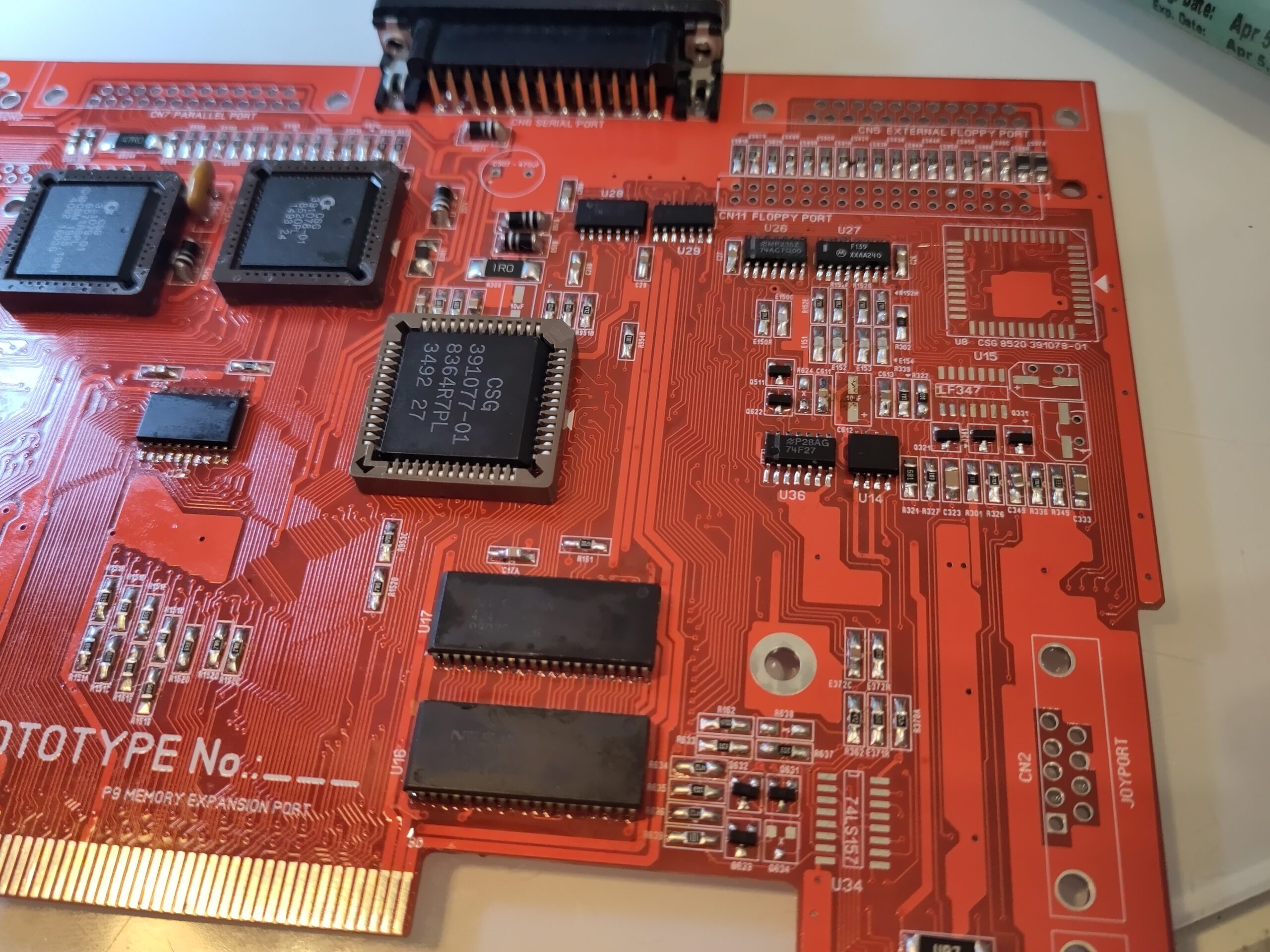
And now DiagROM should actually start and not crash after Chipmemtest is done.
Time to get something on the screen!
add Denise (YES Can be bitchy to solder in with oscillator there)
U31, U32 (74HCT244 WIDE) and U12 (the CXA)
OK here we have something to talk about. the Junior 600 supports the original CXA1145 and a newer 2075. IF you use the 2075 you will not need to have the following components installed:
R224, R221, C221, C222, R223, R222, R225 on backside
C459, C460, Z221, Z222 on topside (and throughhole)
AND I have to tell that the Rev 1.3 boards I will have at Amiga37 DOES have an error so your Red signal is bad. this needs sadly to be fixed with a Cut-N-Jump hack:
if you look at bottom (this is hard on the black board. but look closly and you will see)
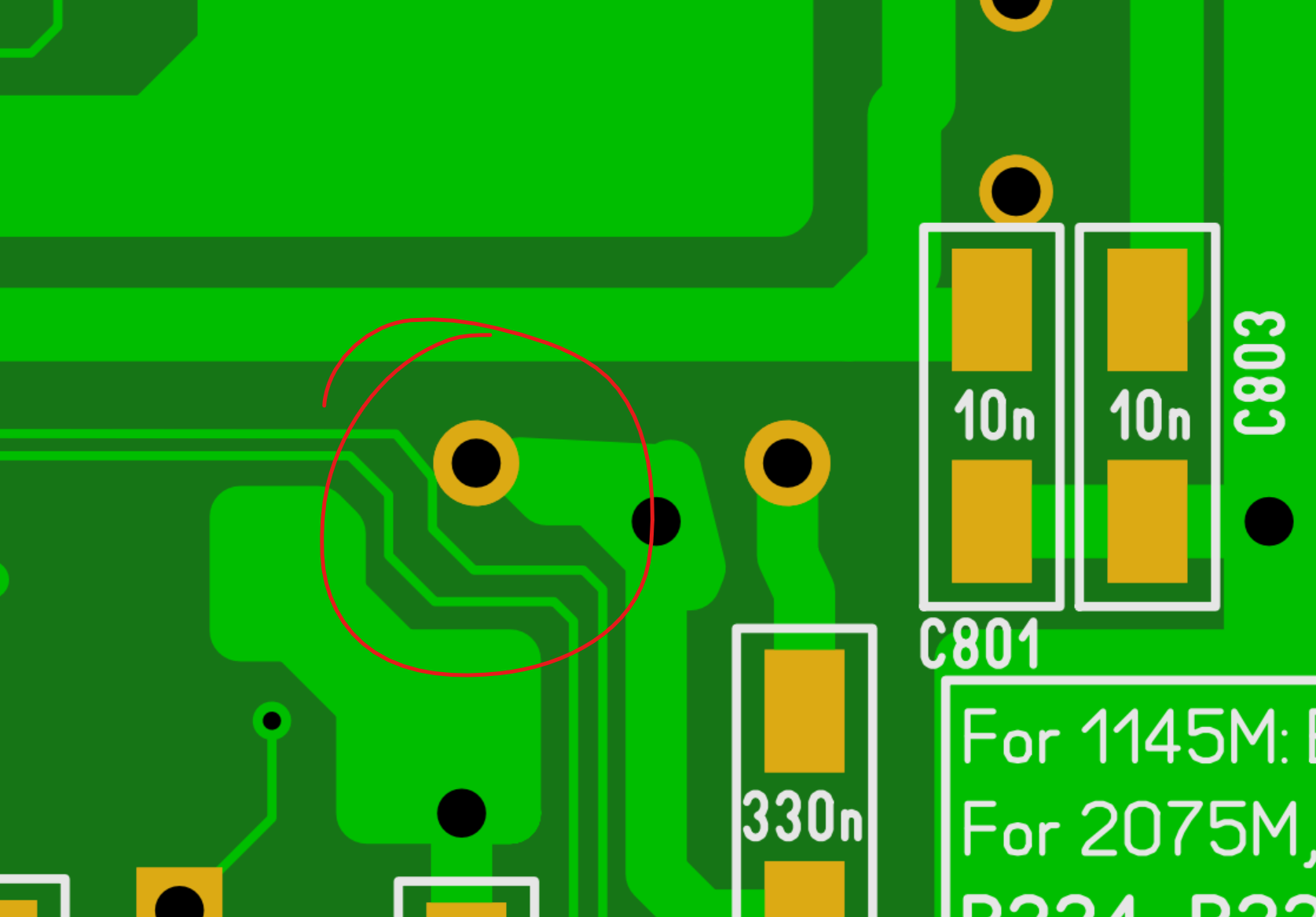
this you need to cut that trace and solder a jumperwire:
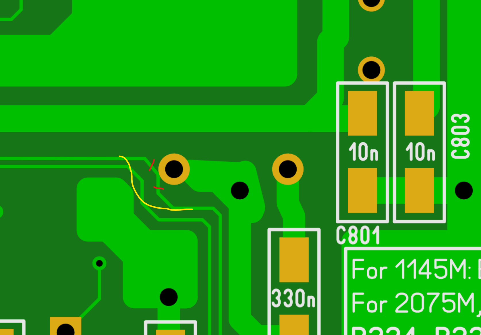
IMPORTANT NOTE! if you are soldering a 1.3 board that I have done the “cut n jump” fix on. be VERY careful when soldering in that through hole capacitor so you do not unsolder my patch. (and as it is also glued in place, that can make a “interesting” smell. solder from the top right corner of that pin!
(HOPEFULLY I had time to do that patch before going but writing this 2 days before my trip start is hard to tell)
Rev 1.3.1 does NOT have this issue. (only the first 20 black and 20 purple)
Anyway THIS screwup fixed, lets go on with the build: you will now have output on the RGB port!
Now lets gets some controls in DiagROM:
U34 (74LS157) and 9 Pin D-Subs (Now Mouse works)
U29 (1489) (Serial IN works)
(sloppy in pictures as no DSubs installed)
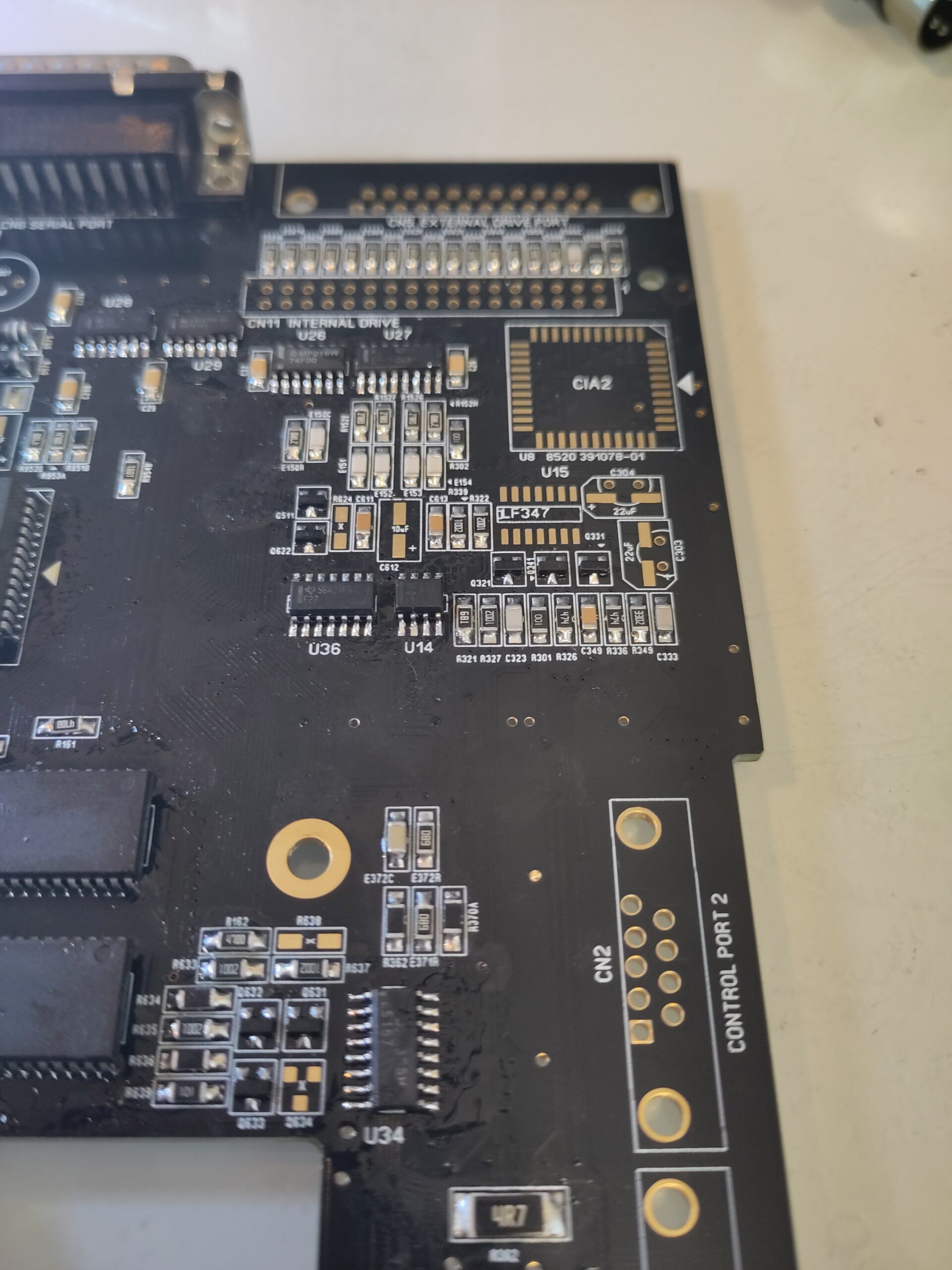
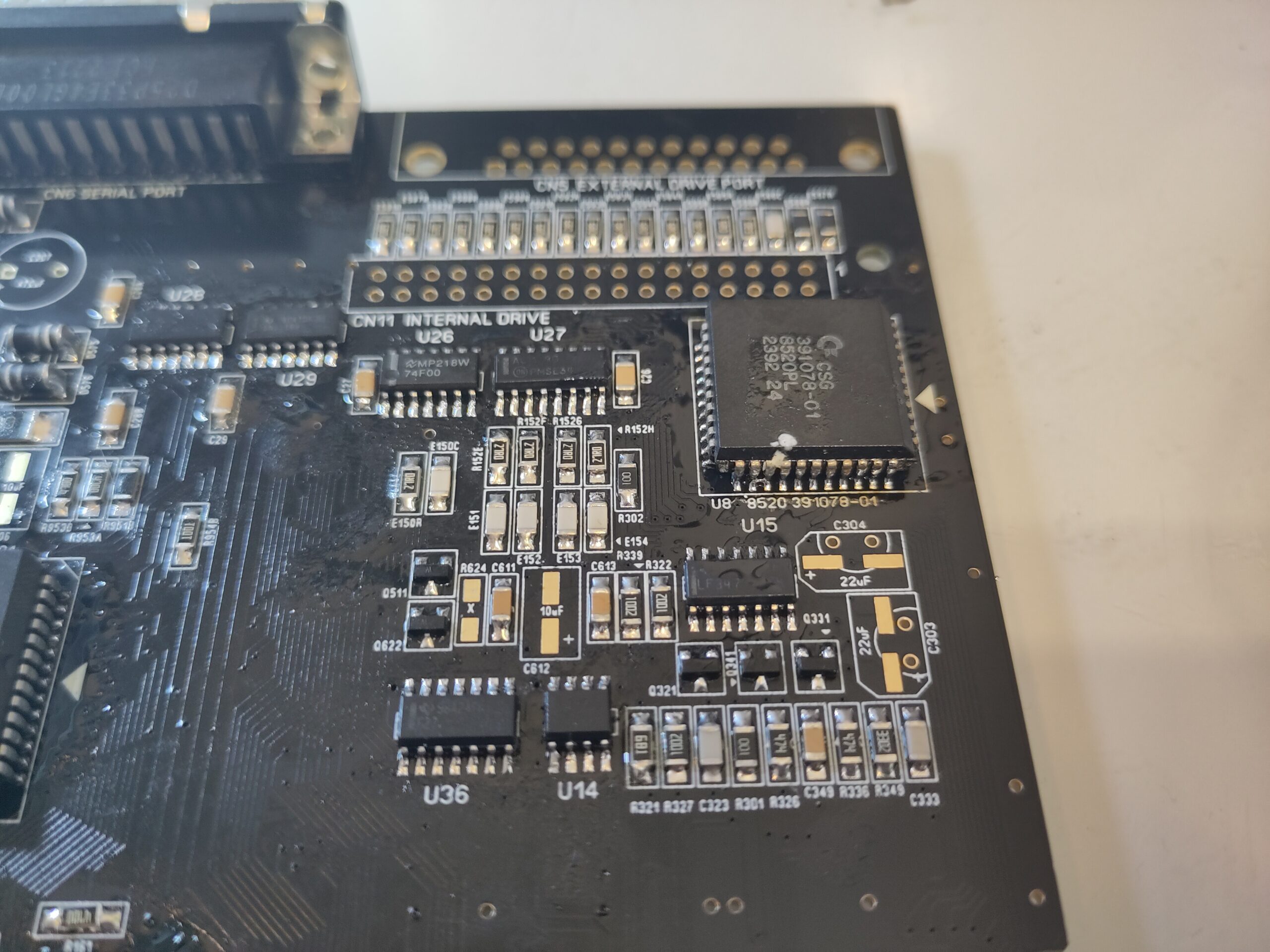
And now is a good time to add the next CIA and the Opamp for audio:
U8 (8520)
U15 (LF347) (Audio will not work as no electrolytric capacitors)
Now lets fix so Composite out etc on PAL will have Color:
U33 (74LS74)
4MHz Oscillator
and IF you have the original CXA the Z221 and Z222 Delaylines)
(Composite out will not work yet as no connector and electrolytic capacitor)
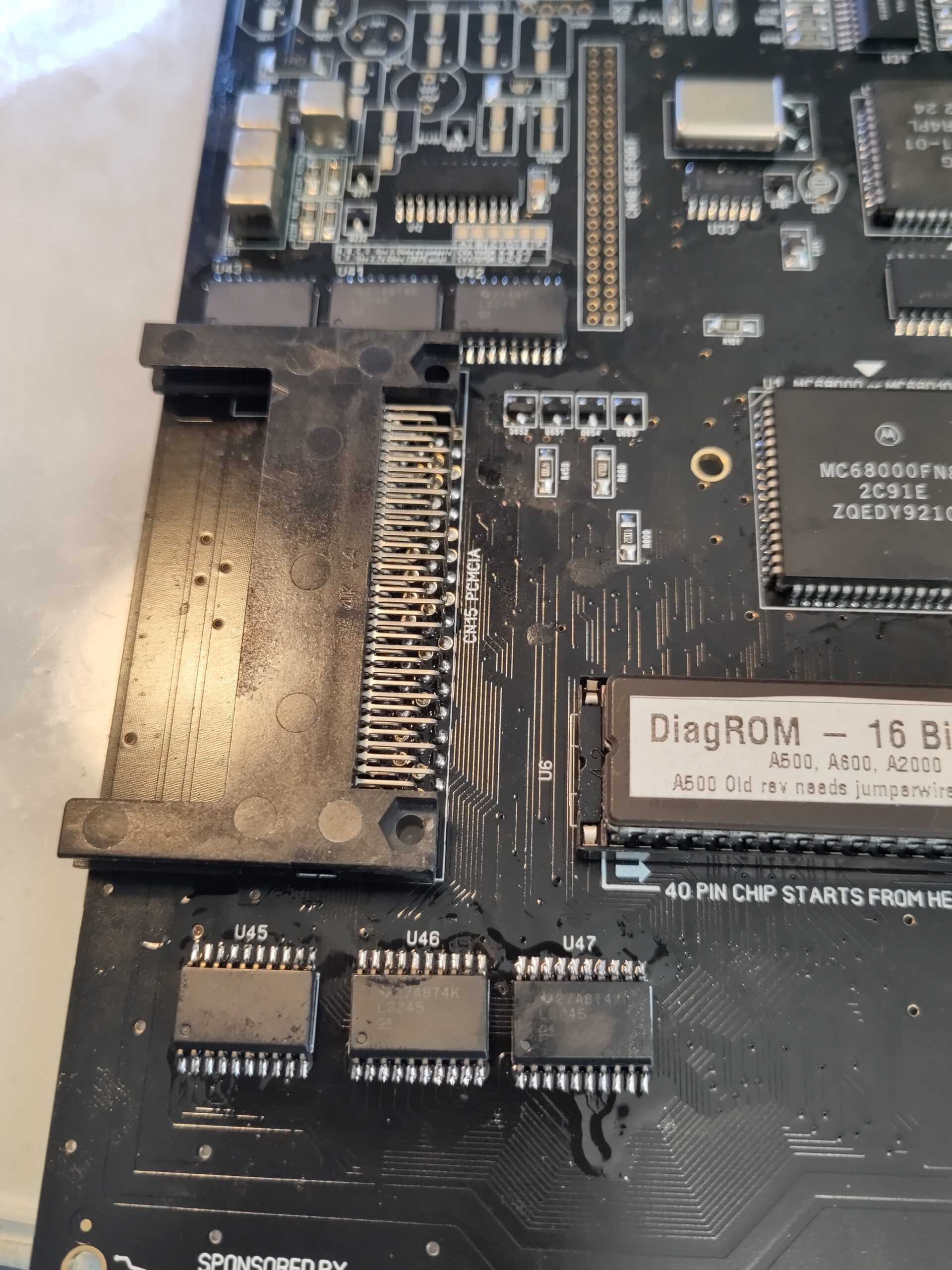
And time for the PCMCIA:
U44 (74F02)
U41, U42, U43, U45, U46 and U47 (74LS245 NOTE of the orientation it is easy to flip them wrong)
and Add the PCMCIA connector.
While we are at it. almost done. actually solder in all connectors now, ports, RCA Plugs, Keyboard connector, floppy power, floppy connector. everything.
IF you want to keep the original RF Modulator you can add it aswell. but DO insulate the board so the pads for extrastuff does not short to the RF Modulator.
AND if you want to use RF modulator you will need 2 resistors.

So simply for 1145, put a 0ohm resistor between pad A and B, C and D
and for 2075, 0 Ohm between B and C, 2.7K between and E and F.
this is for audio to the RF Modulator. so you can skip this if you ignore the RF.
Machine will now boot Workbench. (but not on Composite etc as no electrolytics)
and reason why I take electrolytics last is that it is not recomended to do ultrasonic clean with them on.
So Clean board and put in the electrolytic capacitors:
You can skip 3 100uF capacitors as you can see if you do not use a RF Modulator.
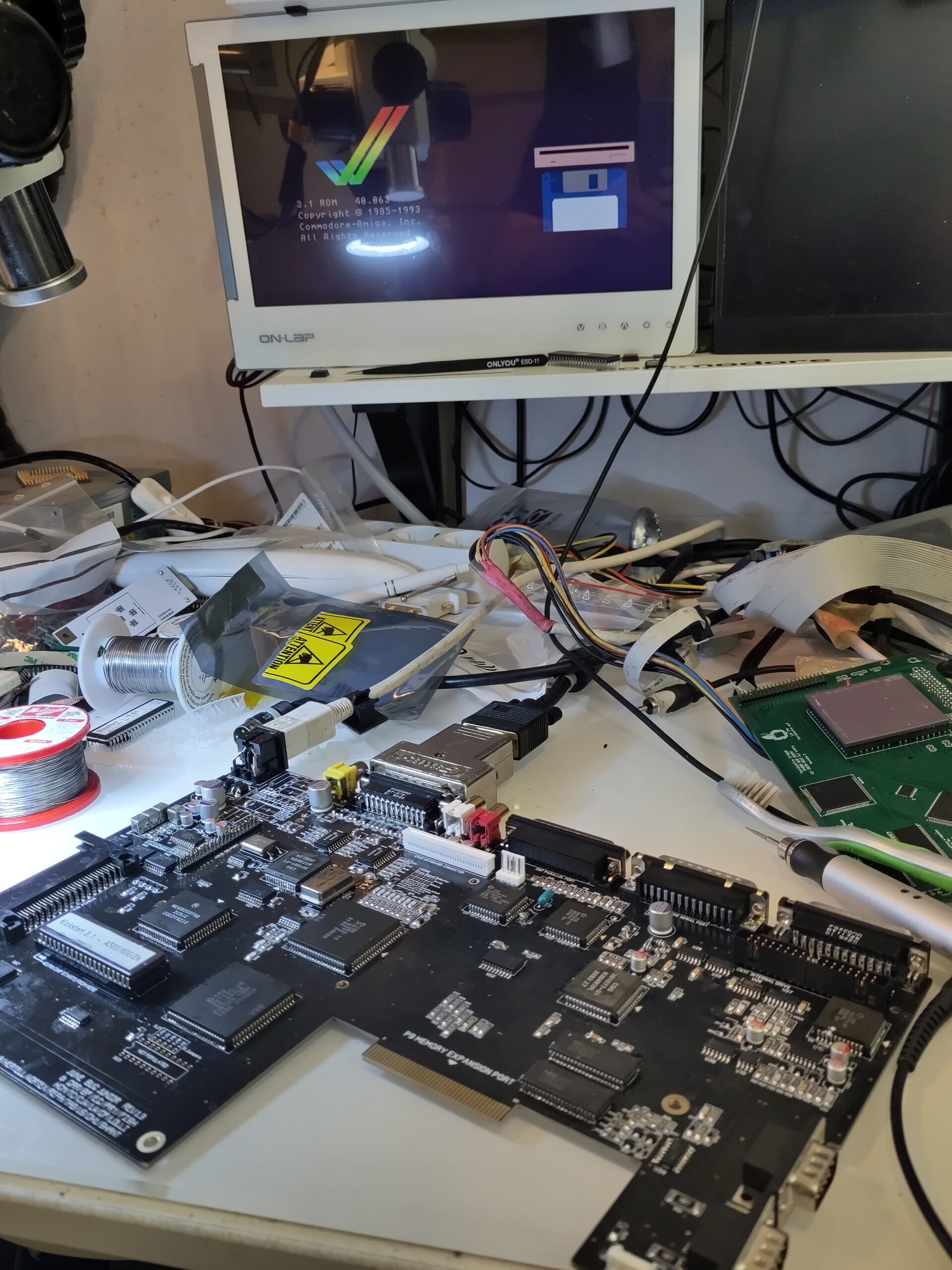
time to start it up and enjoy it:
Wouldn’t it be a nice challenge to make a Laptop out of an Amiga 600 ?
Redesign the motherboard, so that you could use LED monitor.
The A600 keyboard is in perfect size for a laptop. A battery could be a problem. But the laptop case could be created in a 3D-printer.
http://www.bambi-amiga.co.uk/amigahistory/suzanne.html
many have done. but for me nahh. Amiga draws so much current etc it would be “useless”
Hi just wondering where i can get a a600 junior motherboard i seem to be able to buy them fully built but can’t seem to find just a board on its own
Many Thanks
Scotty
It will hopefully be released to the public soon
Hi,
RetroEZ in UK has them in stock at the moment:
https://www.retroez.com/shop/Amiga-600-Junior-1-31-Replacement-Motherboard-Black-p708676178
Also in Hungary:
https://idoregesz.hu/product/amiga-600-junior-graphite-v14-pcb-board-with-autoplaced-passive-parts/
What has changed with V1.4 of the board compared to V1.3.1?
irocnially now I cant remember what differs not that much. it is Róbert that is the mainperson behind this project
I’ve built a couple of Junior 1.31 boards now, and I have noticed on both of them that if I use a Furia accelerator, then writing files to PCMCIA CF card doesn’t work correctly (no errors, but files are different when compared after copying). The same set up works fine on a standard CBM A600 board. I was wondering if you had seen that before, or if you had an idea when the issue could be?
Sorry no idea whatsoever what it could be. how does it behave without the furia?
Yes, without the Furia, my Junior boards are working fine. And the Furia works fine on a standard Commodore A600 board. So it’s like the Furia and Junior do not like each other. I’ve used new components whenever possible. I’m wondering if newer chips (such as the 74LS245s) have very slight difference to the original ones which cause a very subtle issue like this.
Hi Chucky,
A per this thread on EAB: https://eab.abime.net/showthread.php?t=121553 , the problem was with the 74LS245 chips near the PCMCIA port (U41, U42, U43, U45, U46, U47). I replaced them with 74AHC245 chips, and I see no corruption when writing to PCMCIA CF cards with my Furia in place.
Thanks,
Pete