IF moving from a Rev 2B board. please read the note at bottom!!
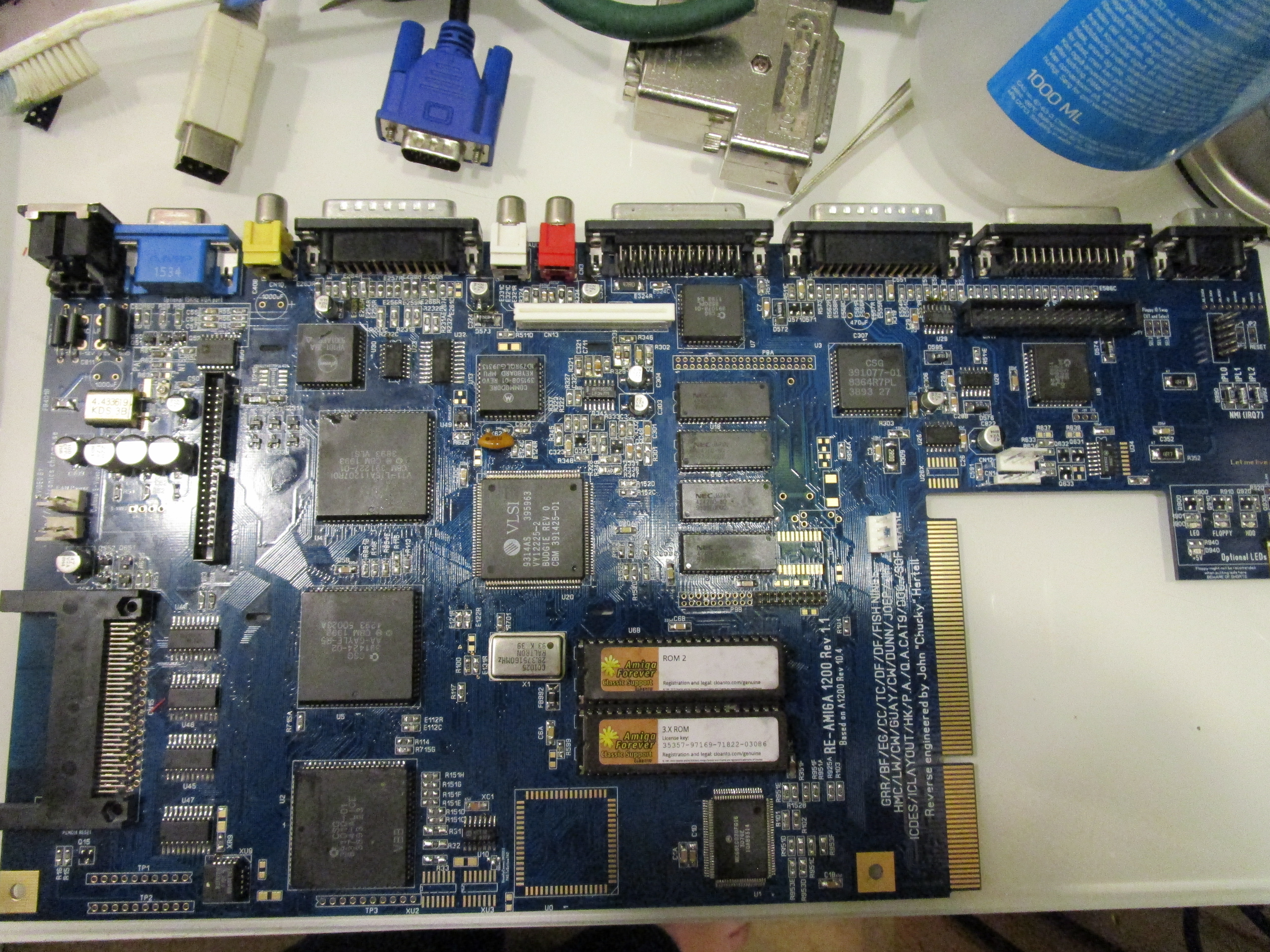
This is a small writeup how to move components from an dead Amiga 1200 to a ReAmiga board. (and basically the same as how to build one)
OFCOURSE there can be dead chips that will make such move not possible, but my experience is that chipset often is ok and the issue is more into a small passive being bad or via/pcb issue.
First of all I want to excuse the BAD soldering on the pictures here as I was out of solderwire and all I was able to get was leadfree crap.
and DAMN it is CRAP so solderjoints looks like I am drunk when soldering.
Remember this is NOT a SMD Soldering tutorial.
First you need to put on all passives. (resistors, capacitors (I skip the electrolyte ones at this point) etc. Nothing real to add about. I sort all components neededm marked. so I can get them fast and correct number of caps. Load the locator and just solder each value at time, first top layer then next layer. There is a 0ohm resistor marked on the locator that is hard to physically fit close to the FPU.
you can skip this for now.
http://www.hertell.nu/locator/locator.php?project=r1200
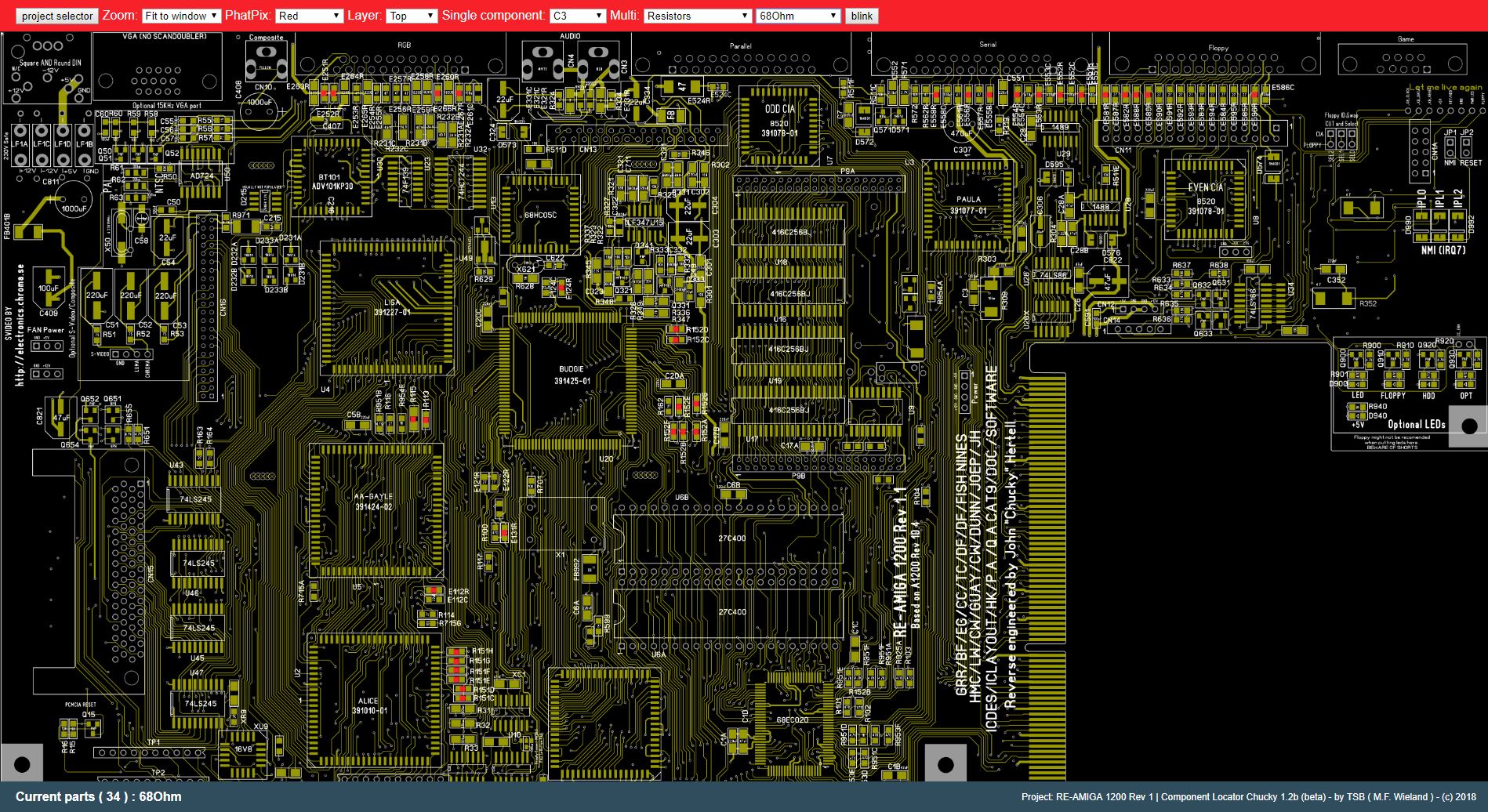
This is the locator, I have selected 68Ohm resistors and you can see every location it is used on this side. and on the bottom left you can also see how many resistors is used on this side.
so now you “just” need to solder all parts. if there is a difference of the value on the PCB and the locator. it is the value on the locator that is valid.
also take a notice that ferrite beads is listed on both Resistors and ferrite beads “multi” selection. This is due to how components are named.
Also if you look at my BOM. I mostly use 0805 size even if pads is 1206. This is as there is no real reason to use the 1206 size that costs more anyway.
When you have done the boring part of putting all the passives (birdseed as I call them) you can remove all components you want to use from the A1200:
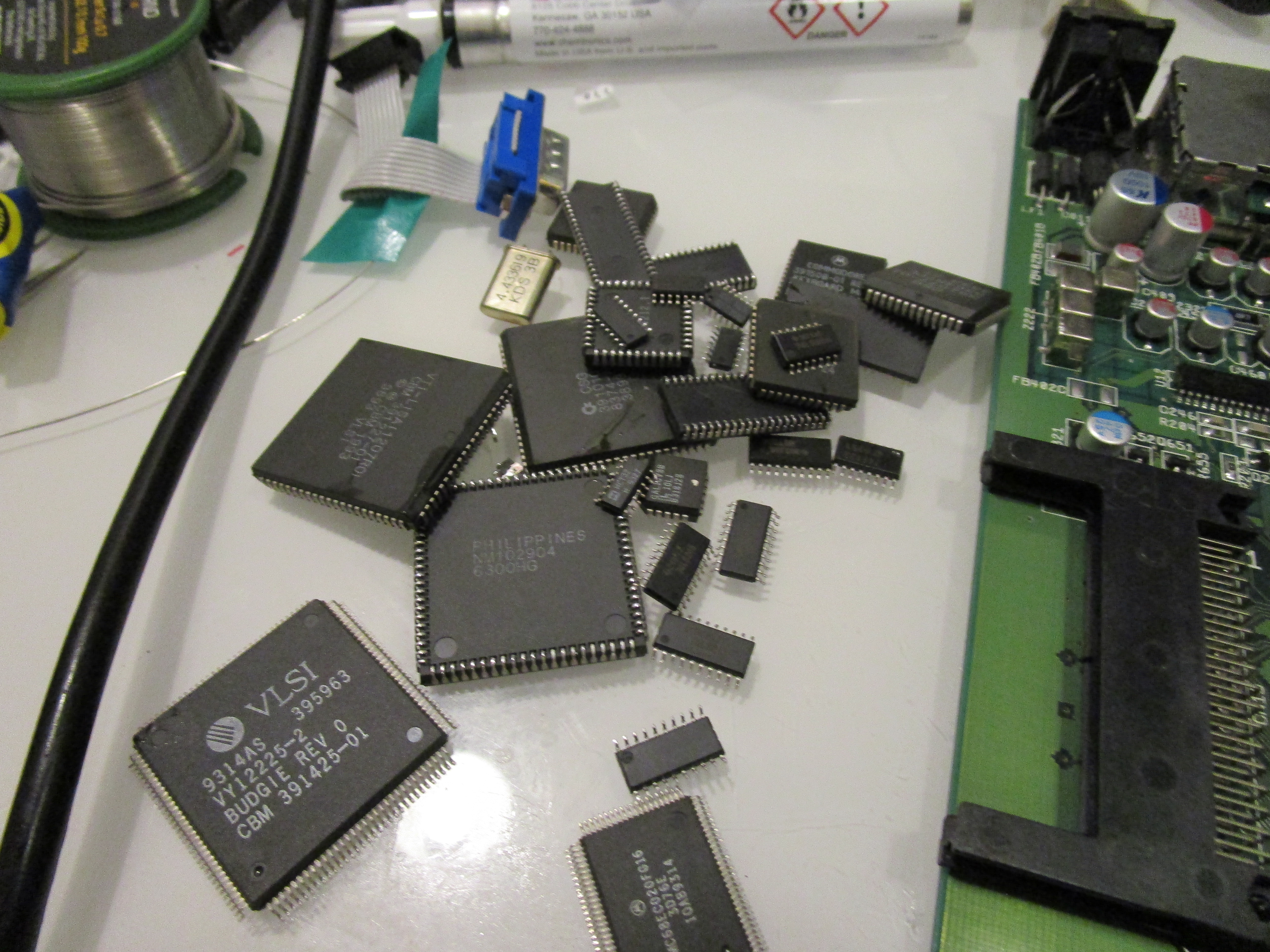

I use all ICs, oscillators and outer connectors. I do however put in new HDD, Floppy connectors. Keyboard connector I reuse due to its price and availability.
but it is up to you what you want to do.
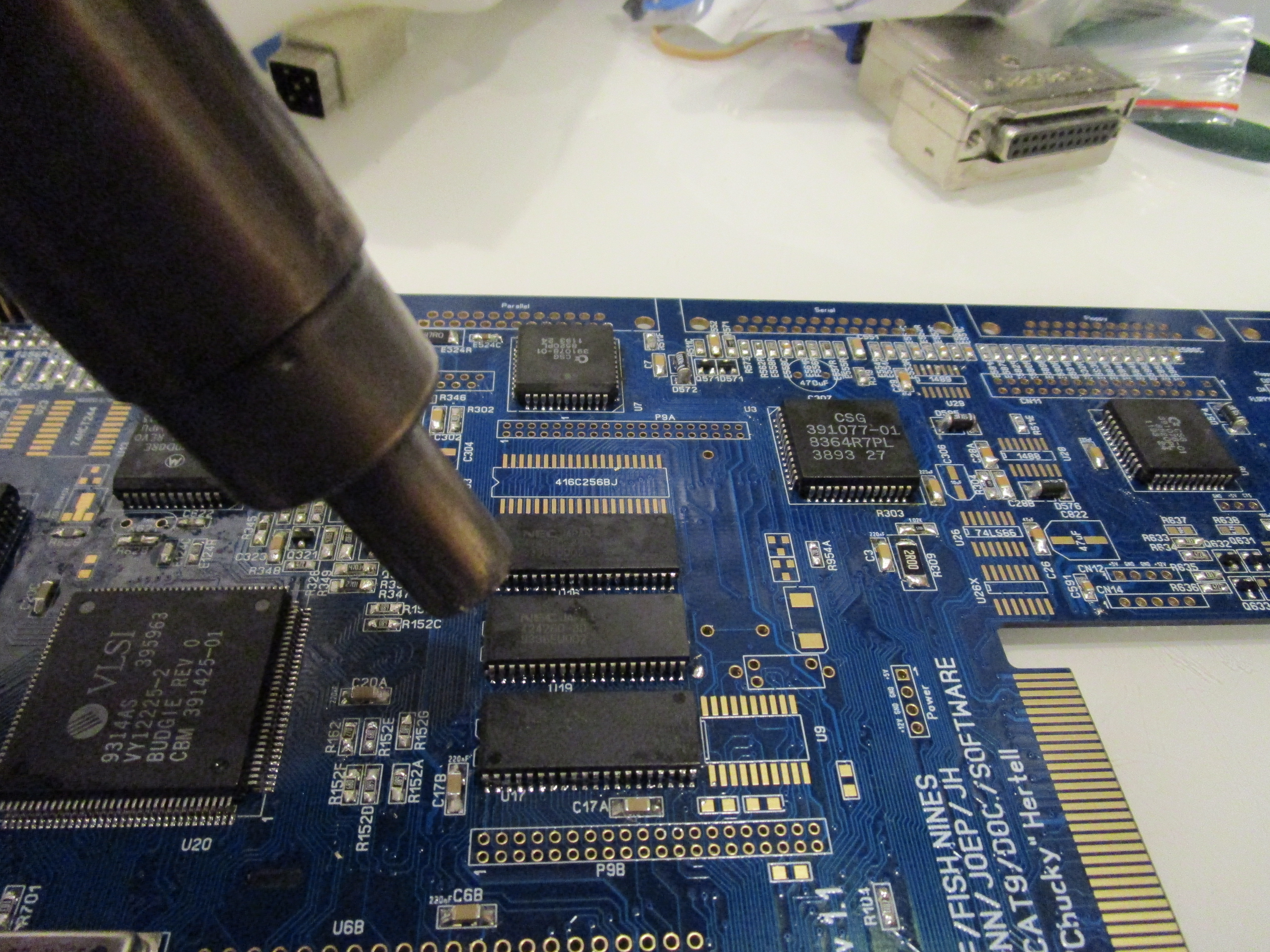
I remove the components with hot air. 280 degrees and time.. I usually put a pair of tweezers under a chip as a leaver. when solder melts the wheight of the tweezers will make the chip move.
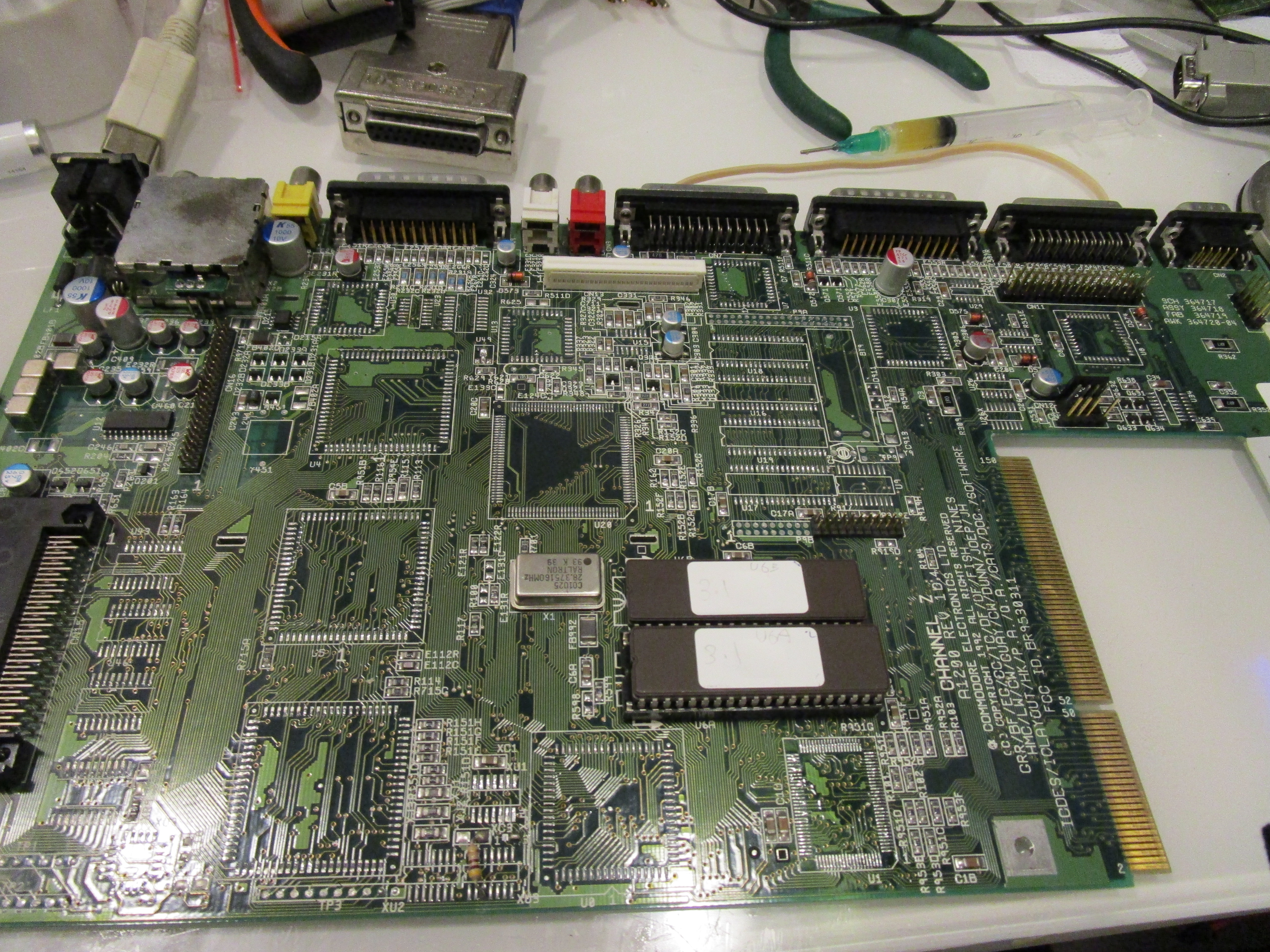
First I install the budgie.
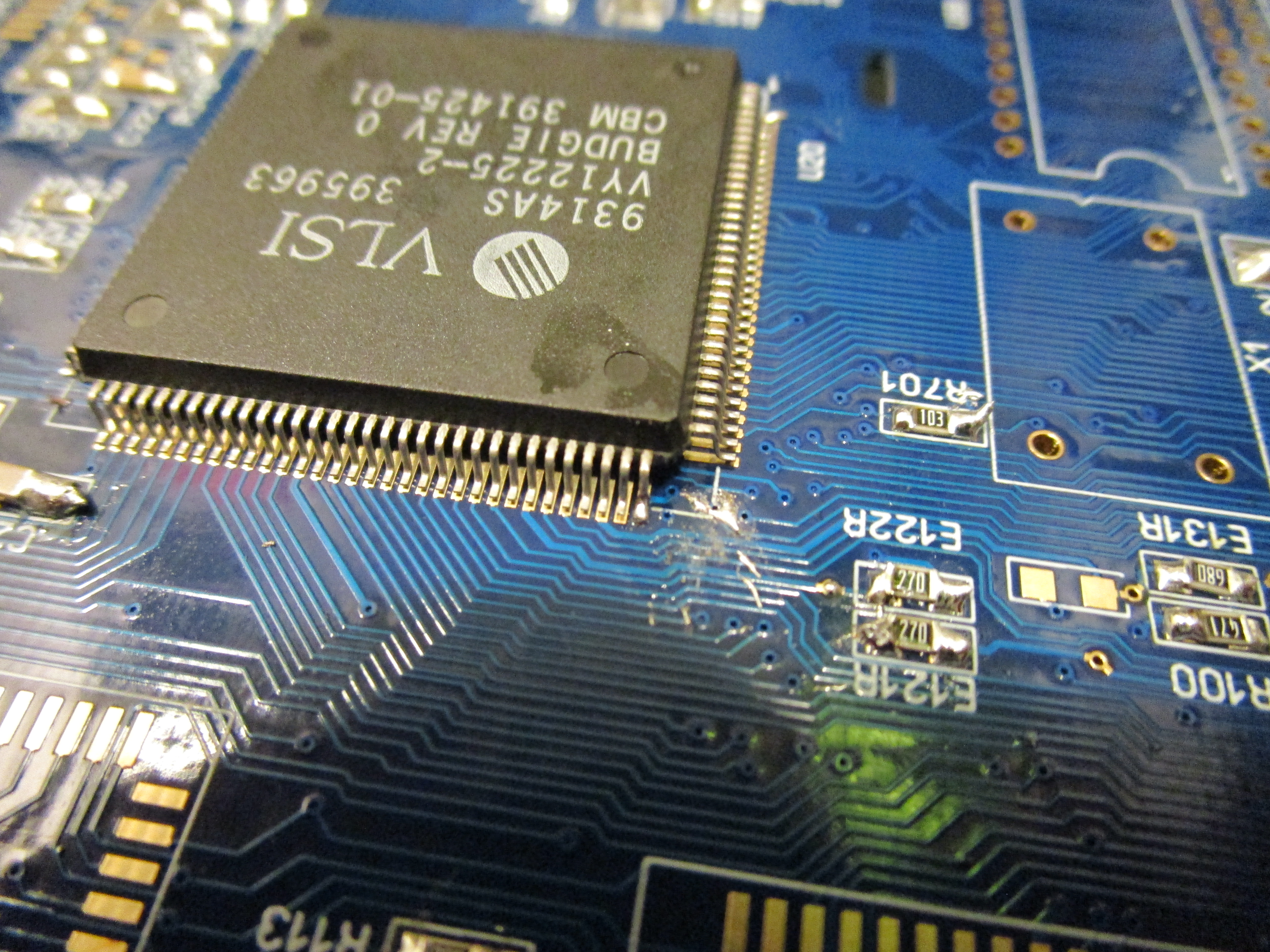
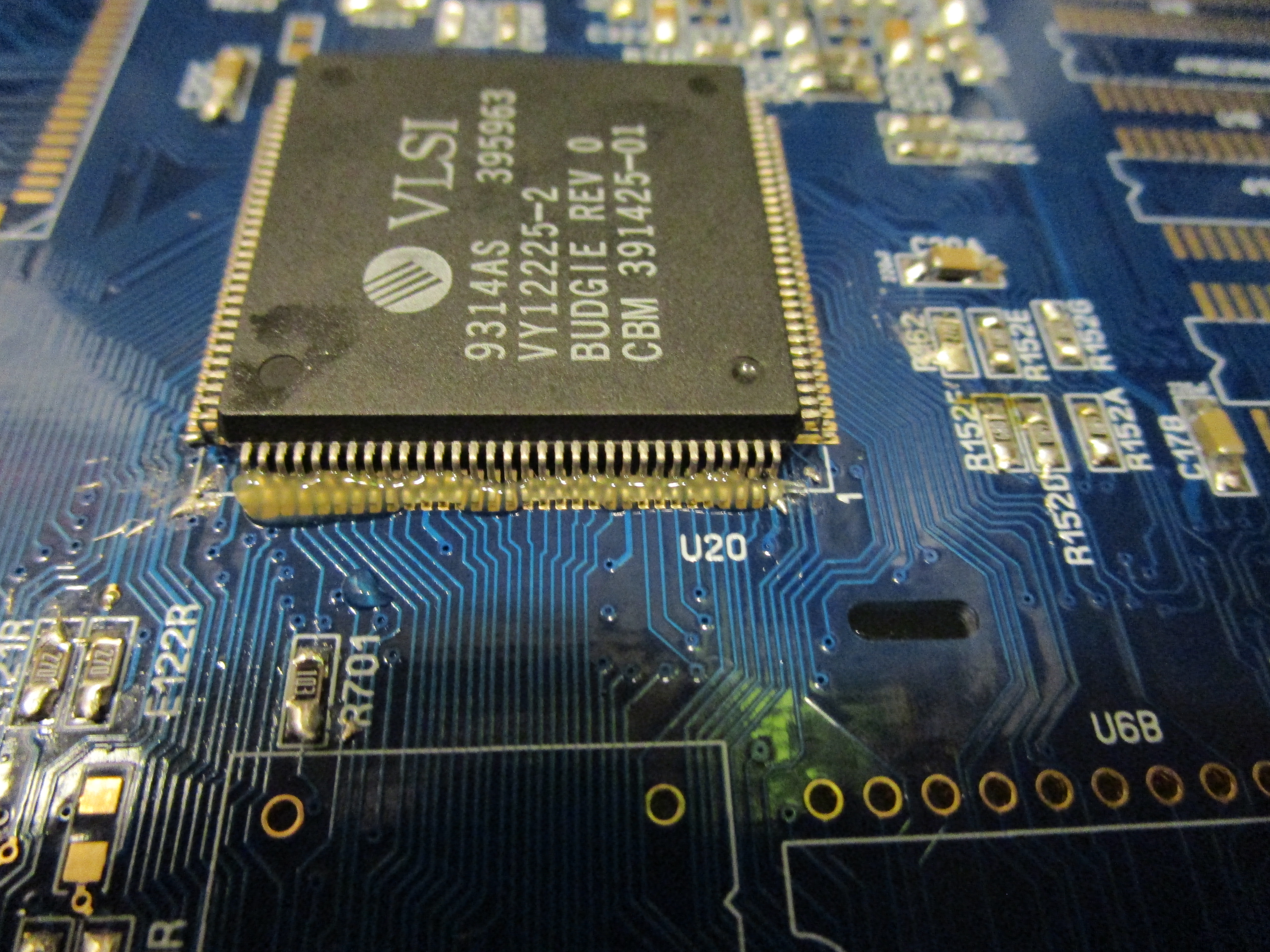
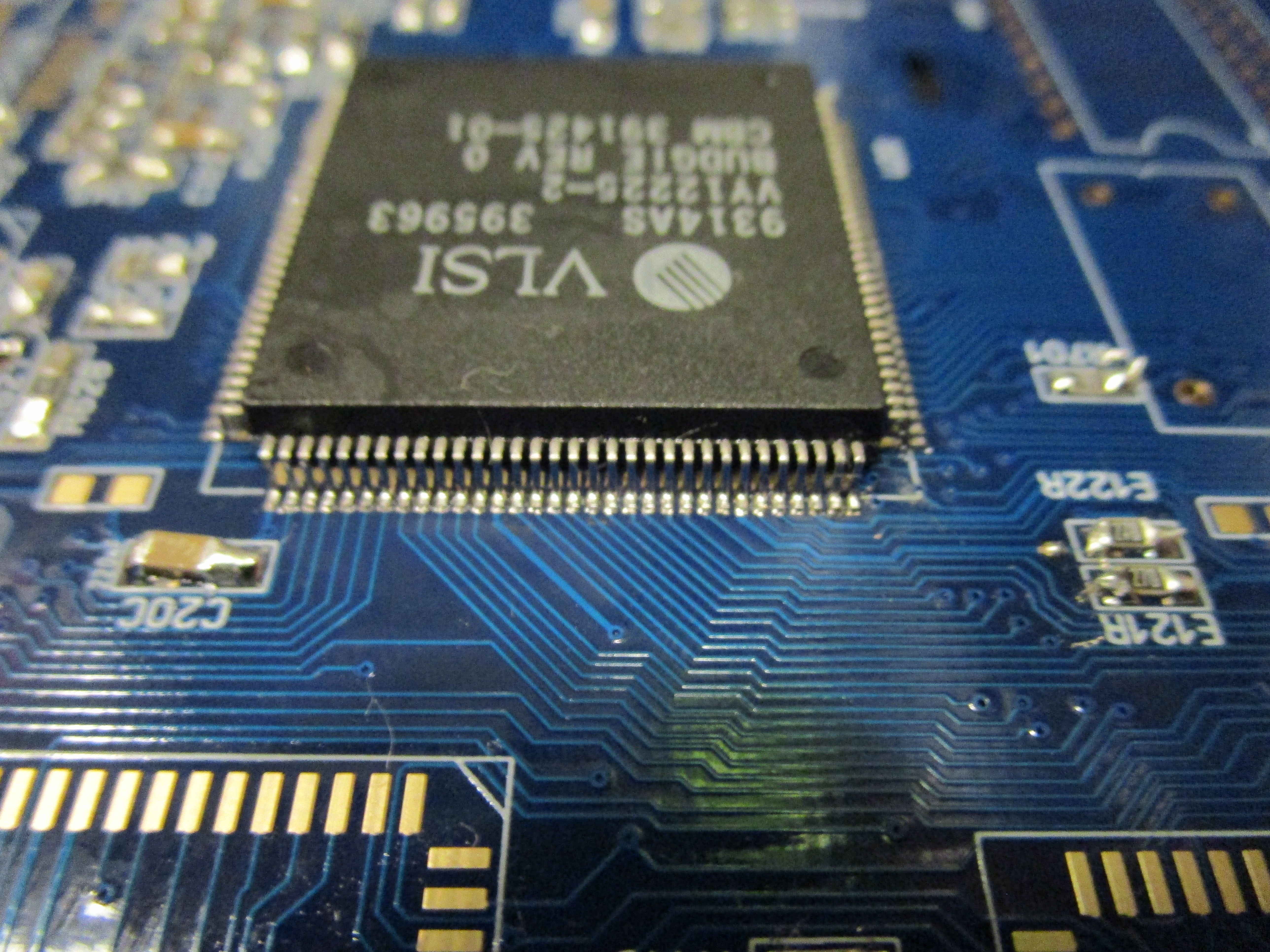
First tack one pin into place, turn the board around and align the pins and tack in that corner. you do not need to make a nicesolderopint here.
take a good look around the chip and make sure all pins seems to be aligned. Now put in flux, remember that much flux helps alot here and I use quite high temp.
so you need to work fast. now with a broad soldertip you dragsolder all pins. (google how to do this! remember this is not a soldertutorial)
To solder the PLCC packages. I solder a blob on one edge:
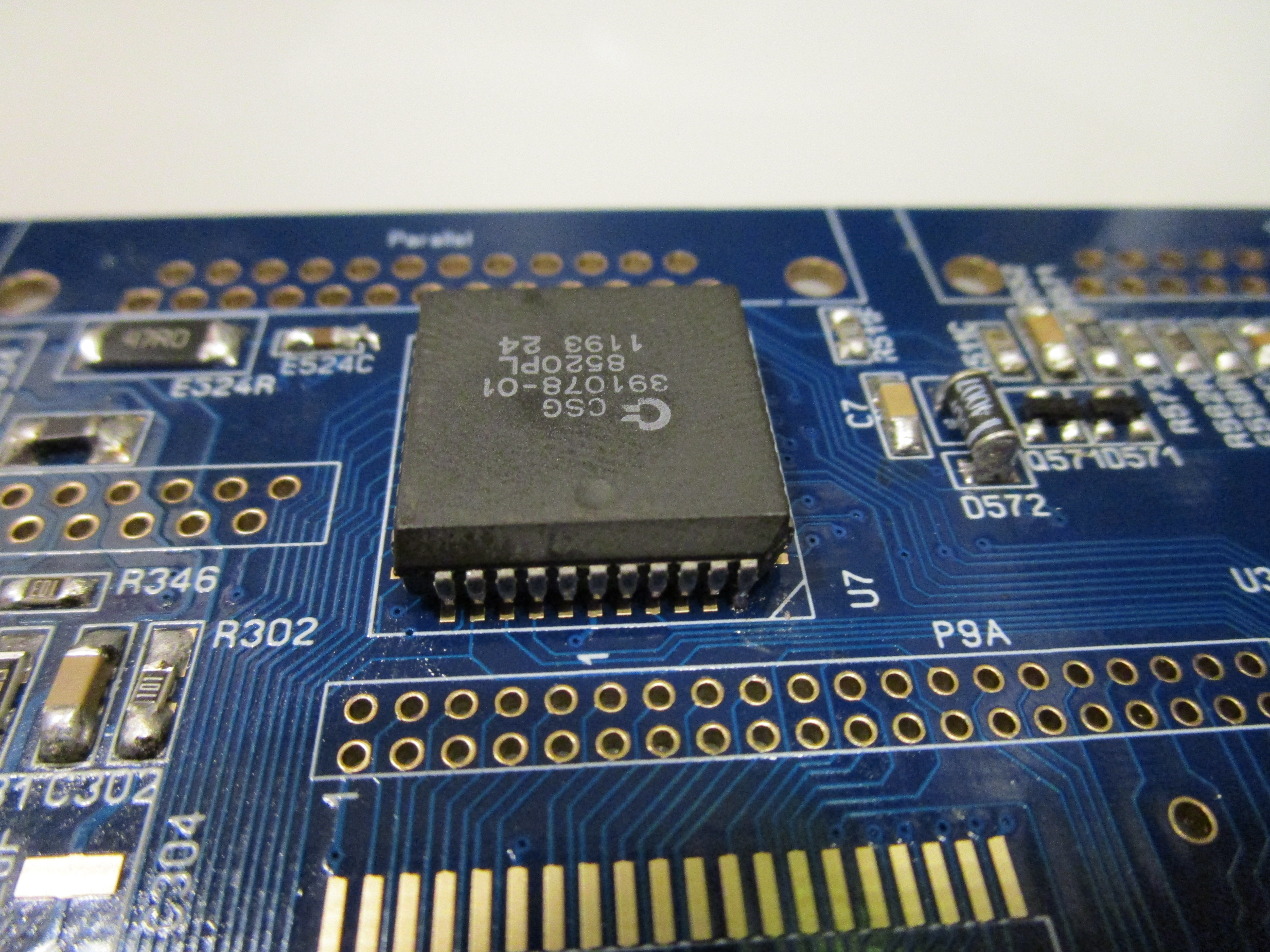

Then I put the chip in place and with your solderiron you make it stuck there. then turn the board around. solder a blob on the other edge while pressing down the chip.


Put on flux, and dragsolder with a wide and flat tip. (YES that big one is what I always use even for the budgie!)
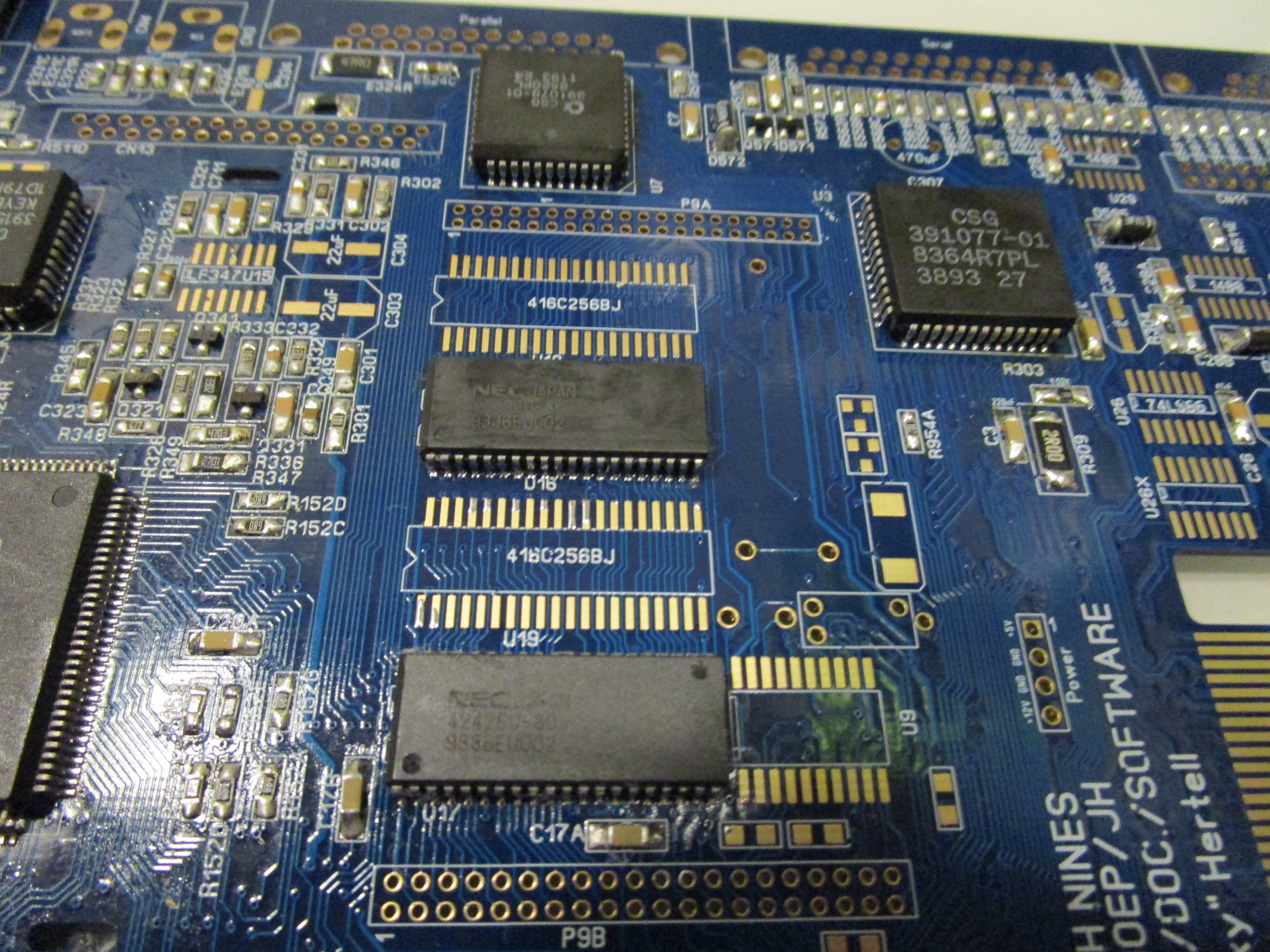
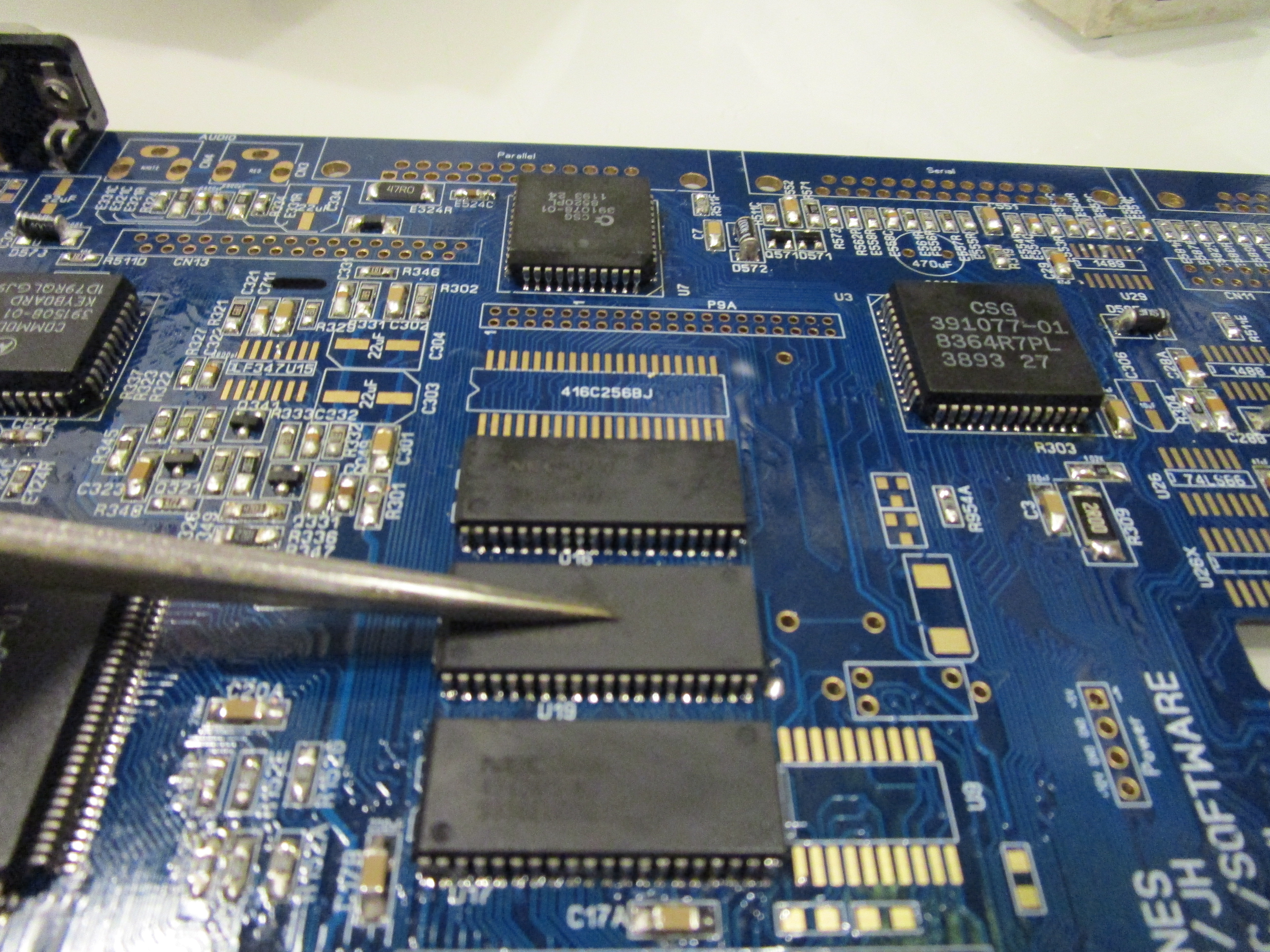
Now time for the memory. IF you had a rev2 PCB. unfortunally you need to find new compatible memorychips as your will NOT work, they have the wrong physical size.
the memorylocation is quite tight. so dragsoldering of all chips can be really hard. but the first MB of ram is more easy to do. I usually just do the first 1 and later after tests does the rest.
When soldering the extra, I found out that this is a easy way to do it:
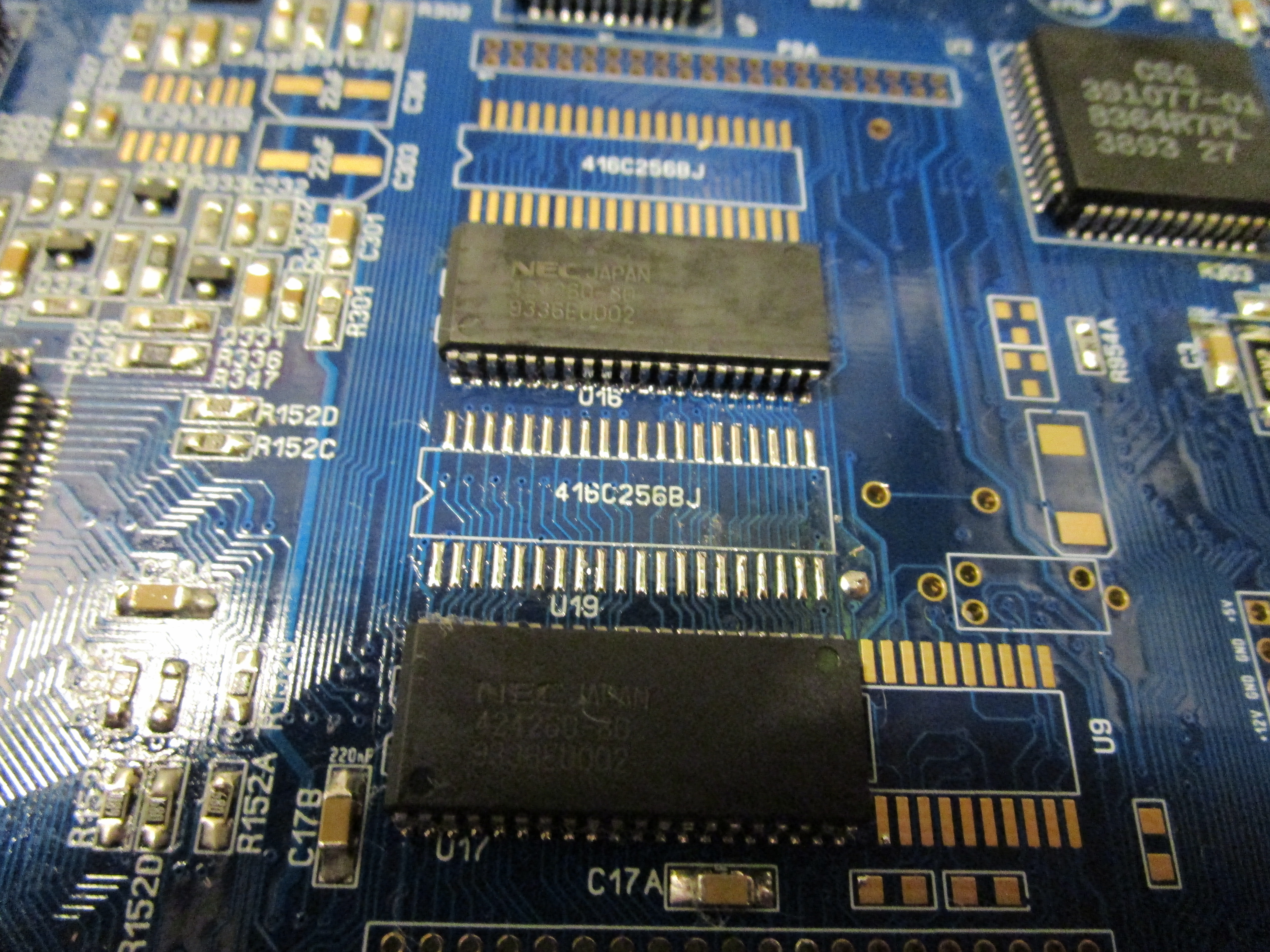
Put solder over the pads, try to get them very even, add flux ontop of it. And put your memorychip gently aligned.
use hotair (280 degrees) and when it melts gently push down the chip so it gets firmly seated while cooling. Be gentle or you will move the chip.
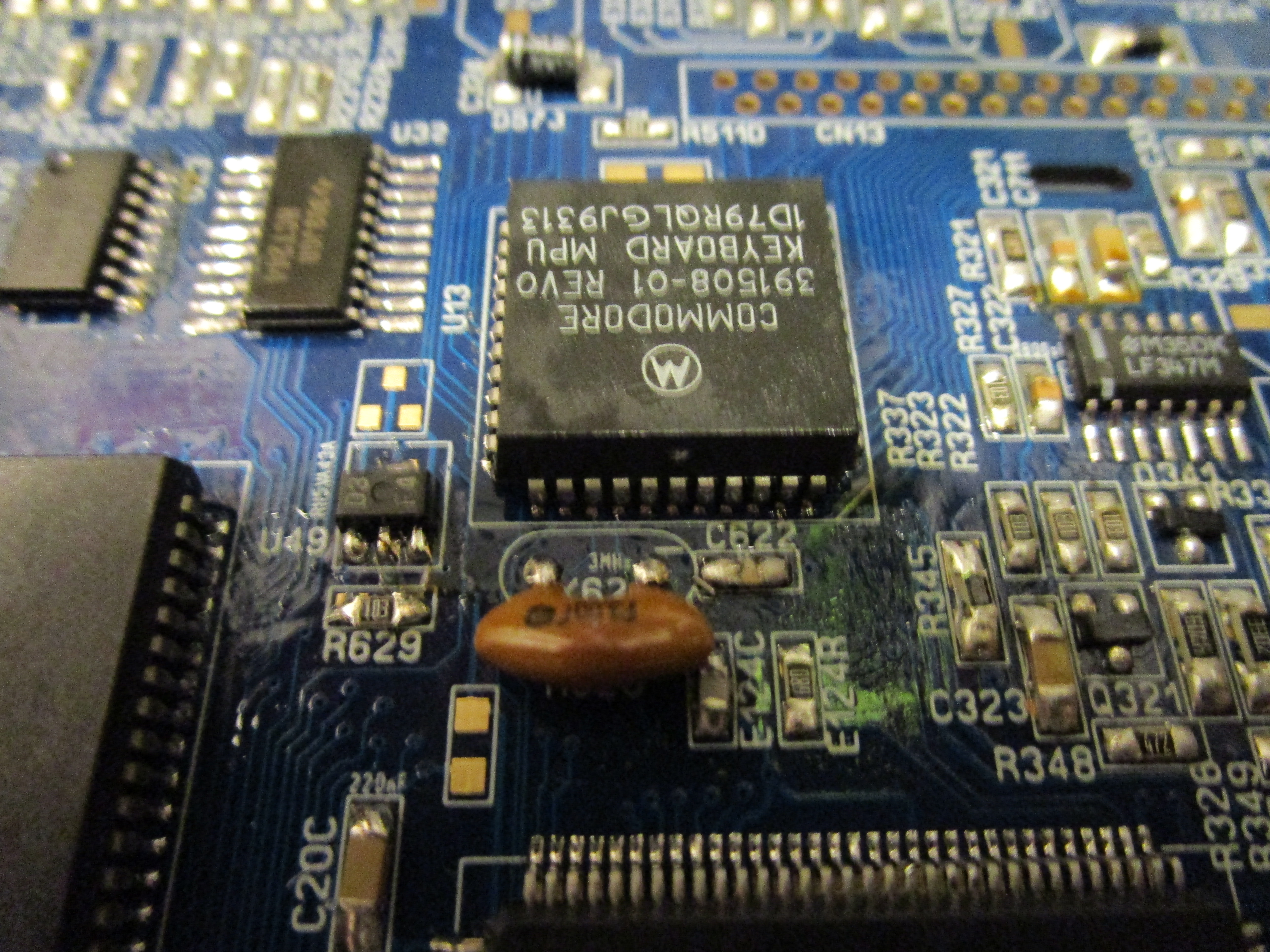
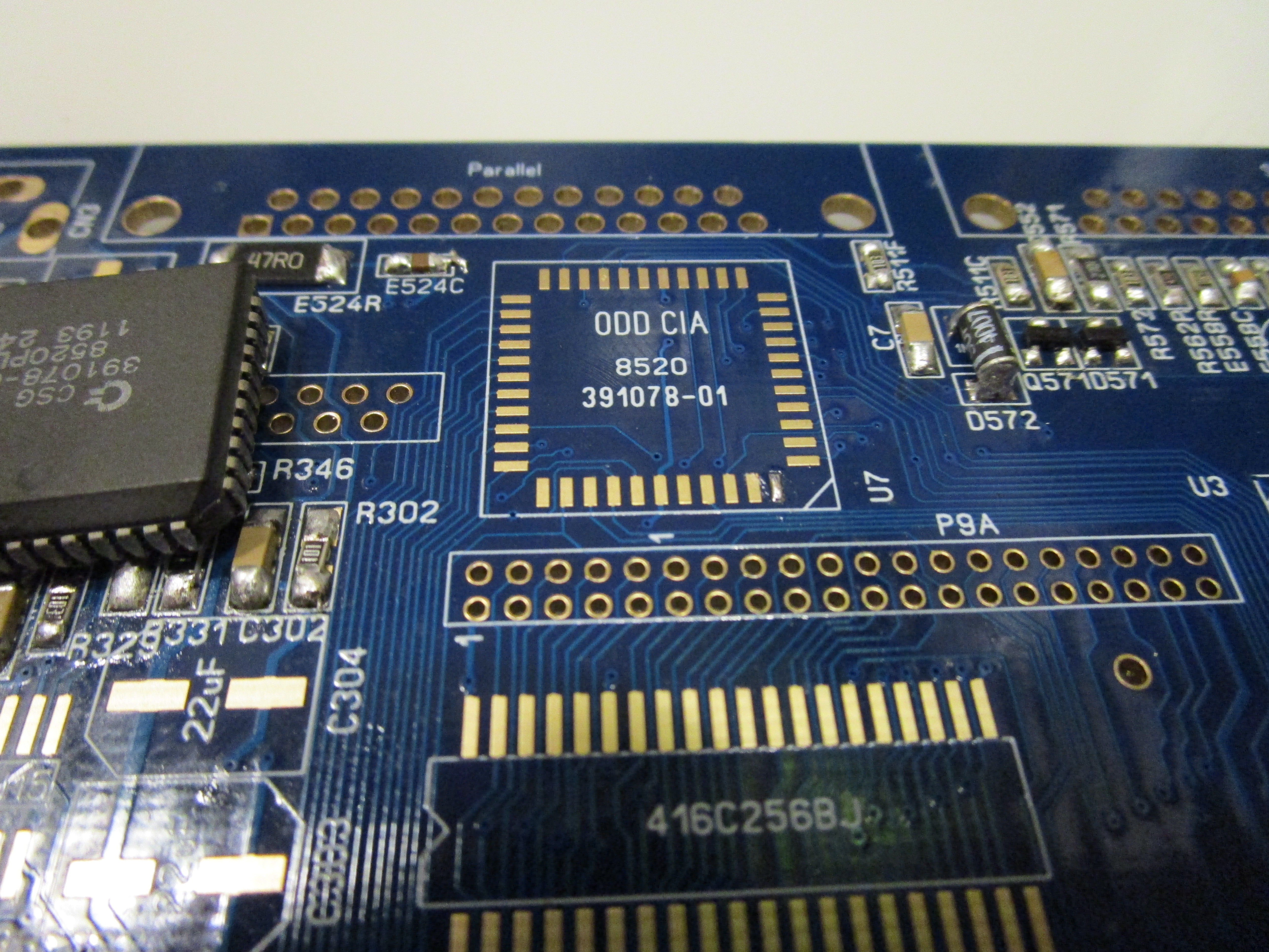
At the keyboard controller do not forget the 3MHz osicllator (red in picture) and the low voltage detector (small 3 pin thing between keyboardcpu and LISA)
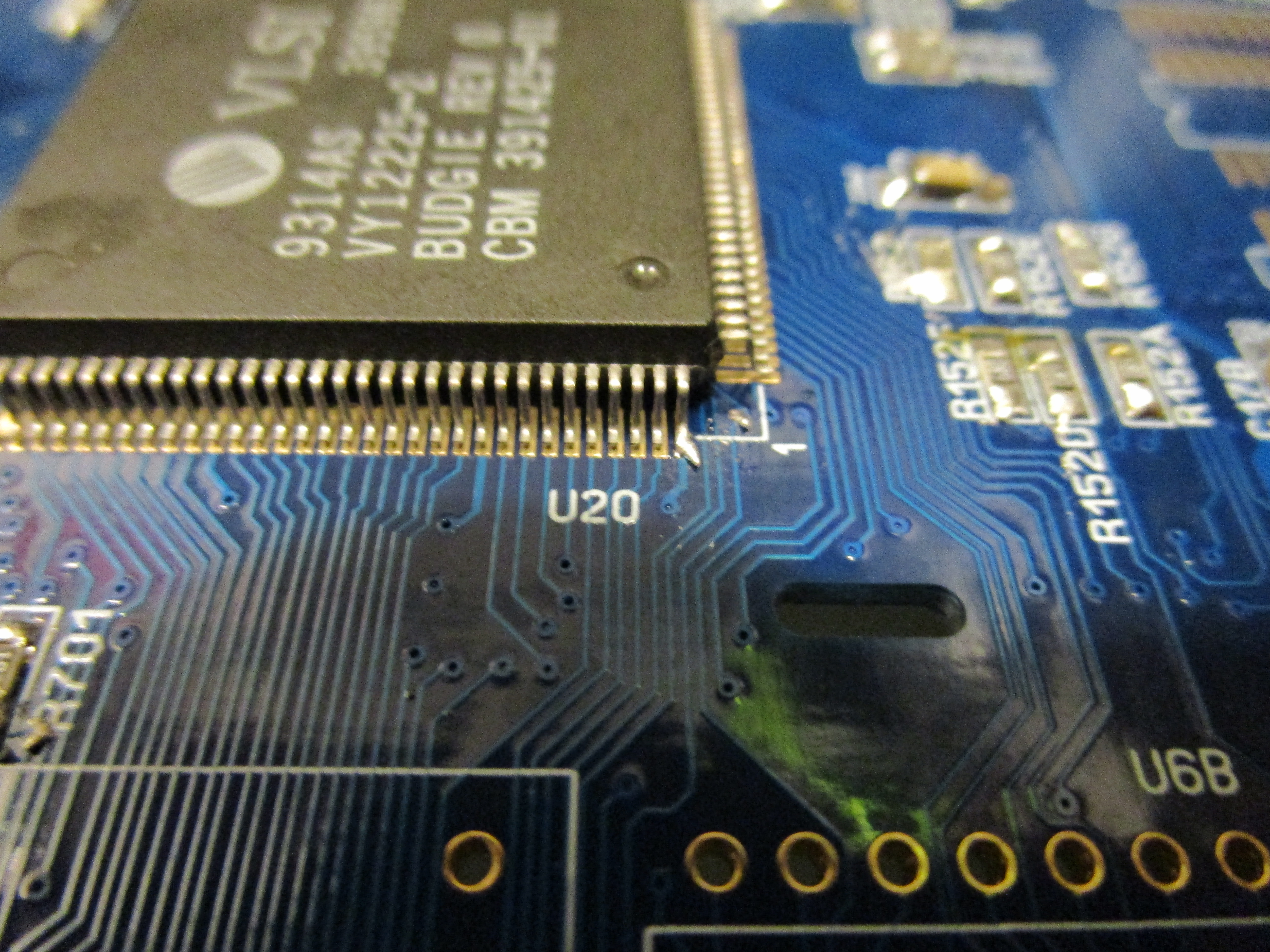
Now the thing that is EASY to forget.. the commodore “dityhack” or what to call it (remember the 0ohm resistor I told to skip.. this is it)
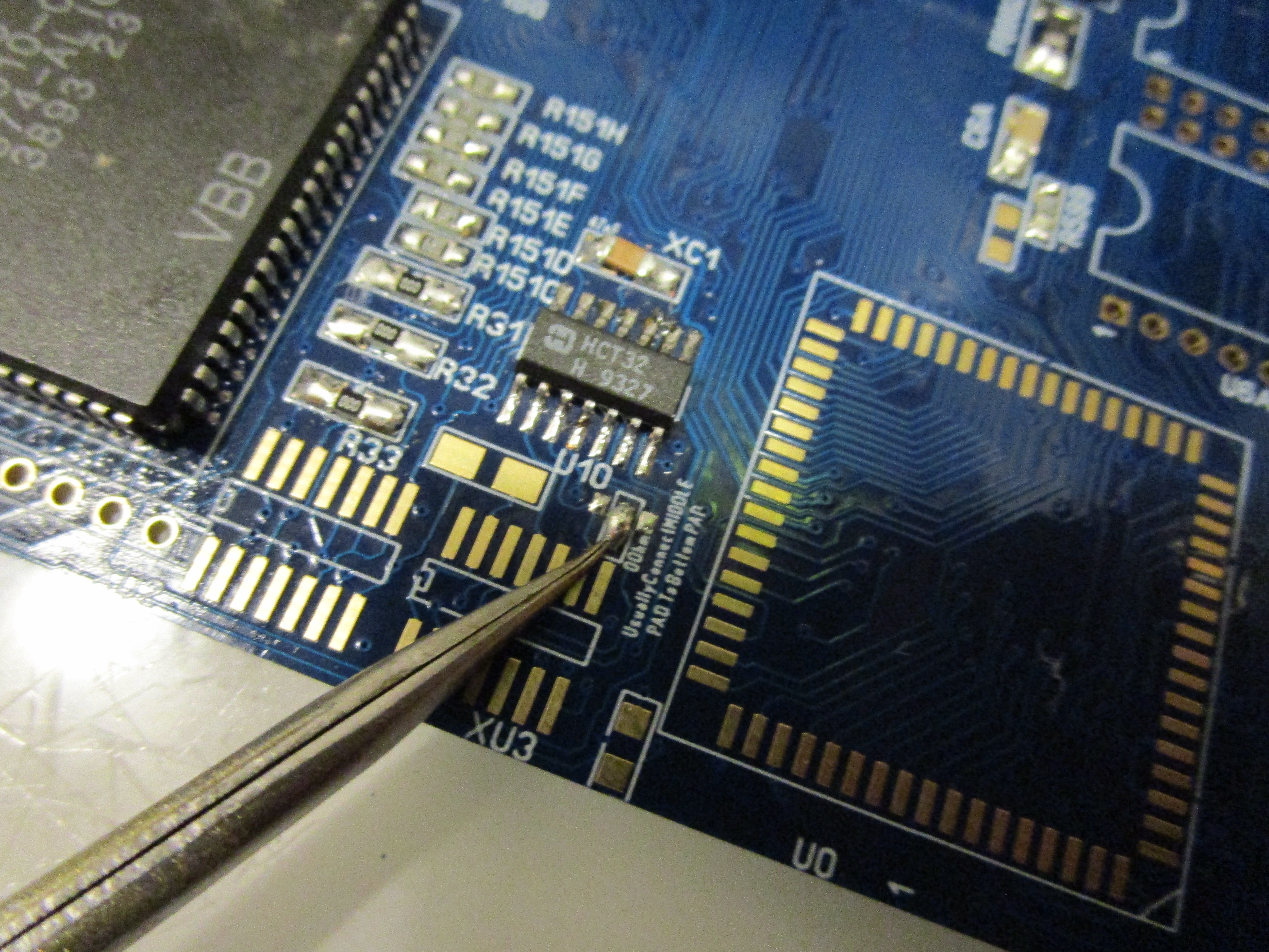
you need to make a blob/short between the middle upper point and the lower point (rev 1.0 PCBs have the lower slightly more to the right while 1.1 have it below the middle point)
and you need that 74HCT32 on that “unmarked” chiplocation you can see there.
Without this solderblob/connection you will NOT get a picture at all.
A note about the Videodac. IF you had that zenerdiode populated you have a older videodac. and there is an issue for that on the reamiga pcbs so far (will change it soon, but will not bump motherboard revision, it will just have a newer date than 2018-08-28.
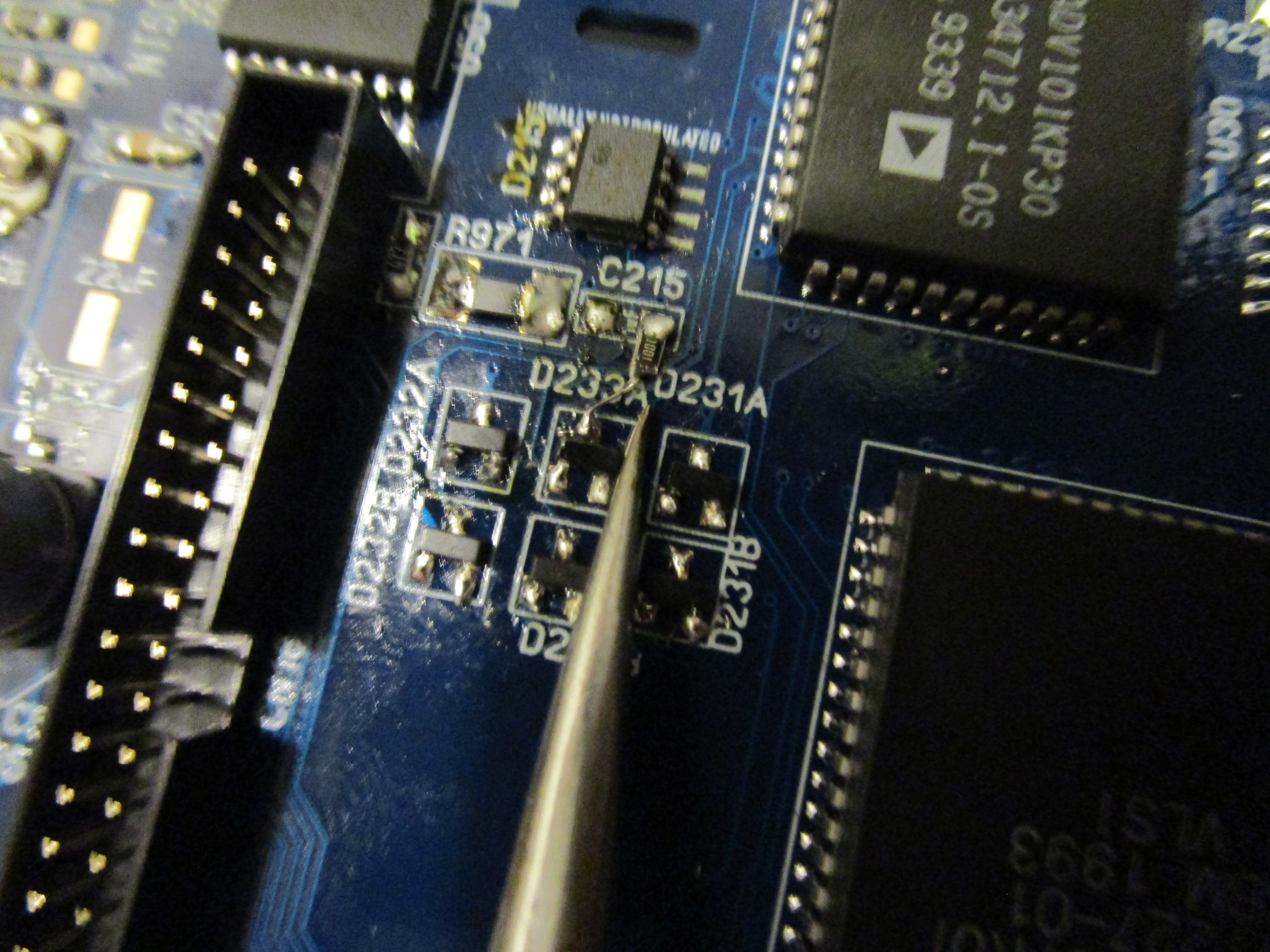
IF you have it (the small IC between IDE connector and Videodac) you need to put a 1k resistor on the RIGHT tab of C215, and solder a wire from the other side of the resistor to one of the top pins of the diodes below. (newer boards will have a empty 0805 pad here for this close to the C215 location)
Testing:
I usually test with a cpu card BEFORE soldering in the 68EC020 cpu.
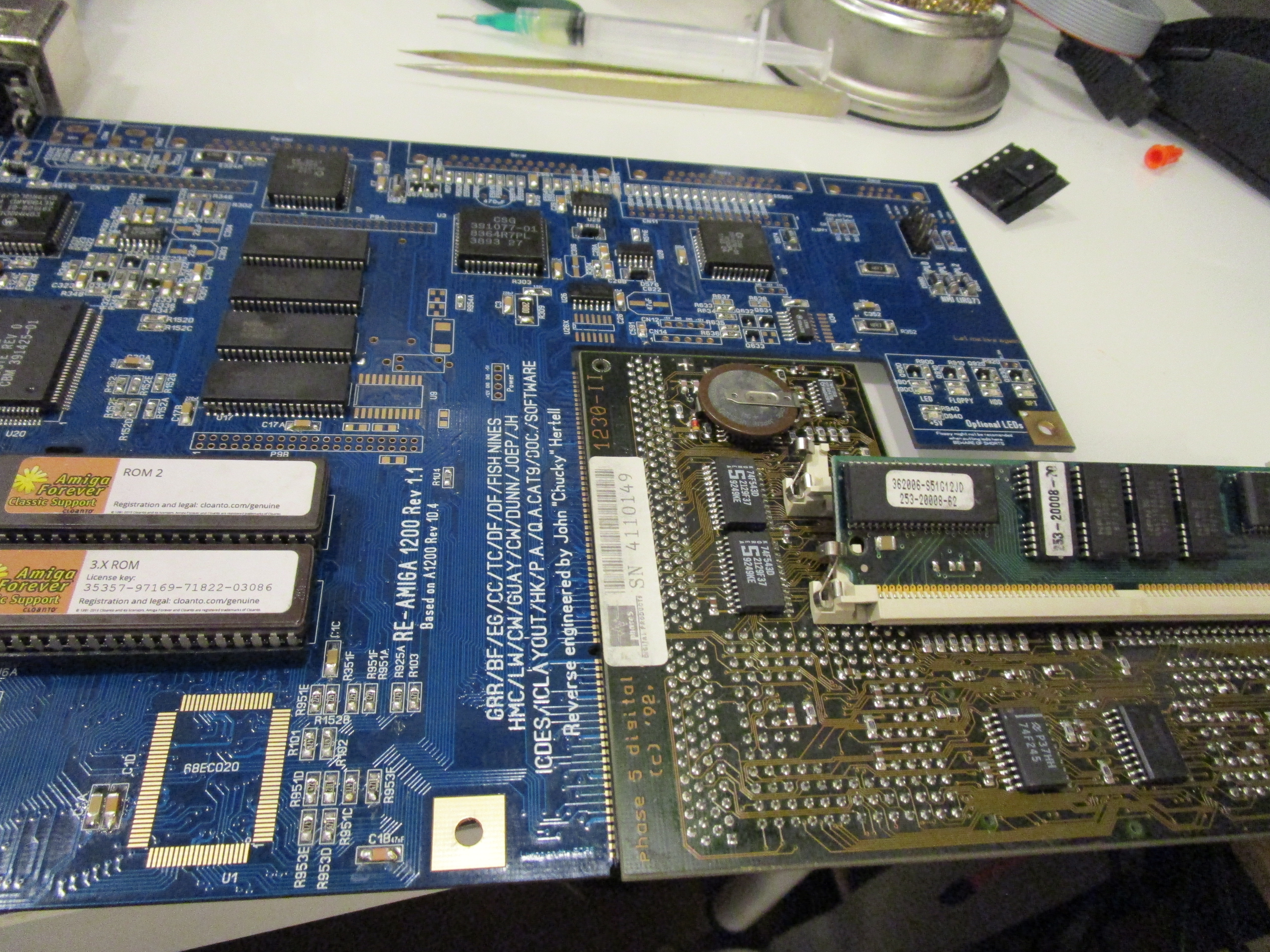
So if you want to use CPU cards, you can skip the 020 that will add heat anyway.

Or solder in the 020 afterwards or before.. remember flux is your friend.
Now for the options.
to the right of the board there is place for optional leds.
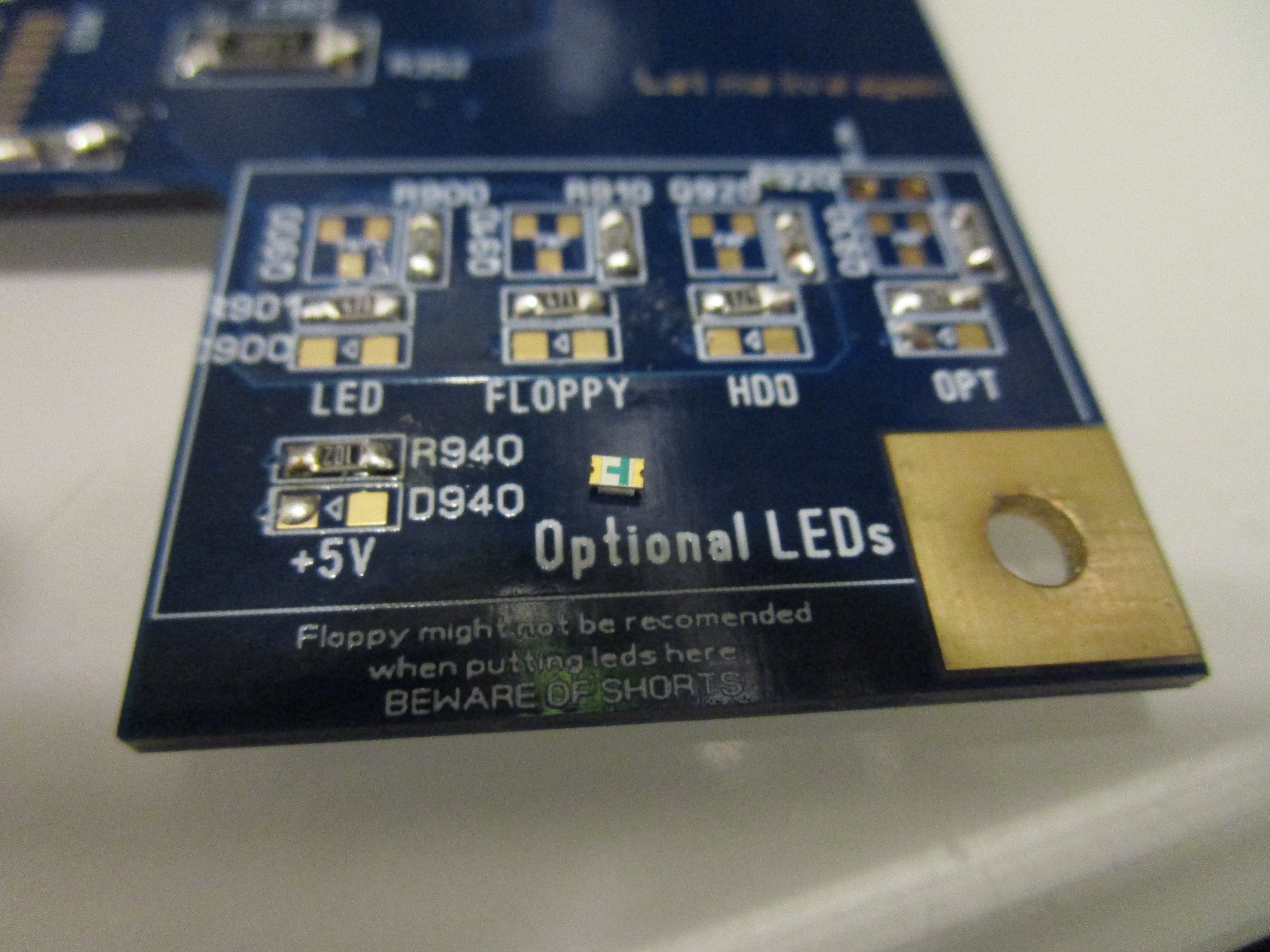
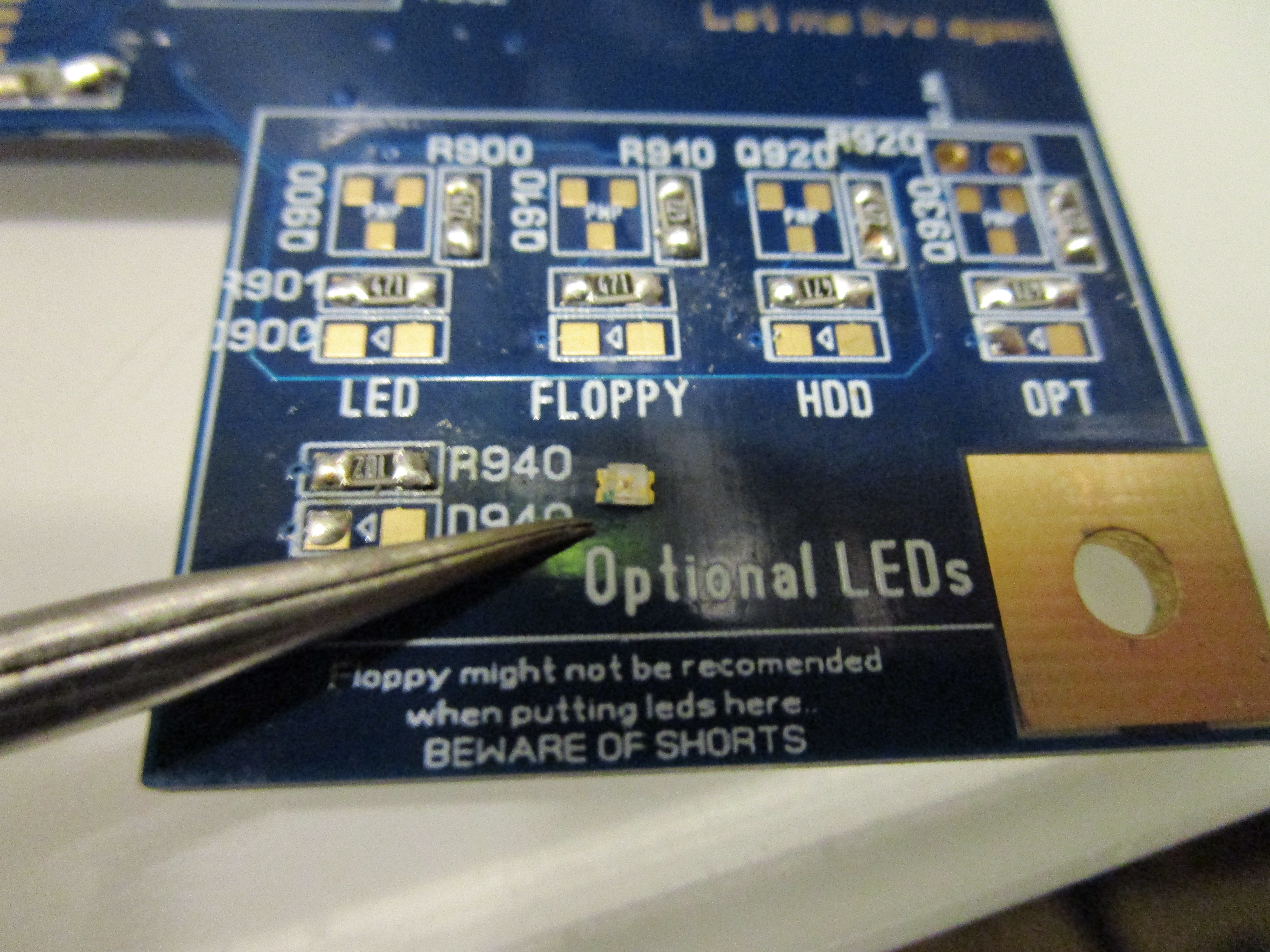
I have put a led upside down on the left pucture. you can see a small green line. if you turn it around you can see a small green (can be any color) marking, this means it should be pointing to that direction as the arrow on the pcb. put it into place use any color you want to. if you think the brightness is not what you want.. the resistor above the led sets the brightness. If you do the maths it should be 33Ohm but as I think that was WAAAY to bright. I used 470Ohm resistors instead.. use what you like. lower value=brigther led (do not go below 33Ohm)
the lower led is for 5V, “real” value should be 330Ohm but I use a 1K one there, to get a more decent brightness. Again up to you.
ALSO! A word of warning: if you populate the boards with leds and use a floppy. It can touch and short the leds. so be aware.
New Composite / S-Video / VGA Connector:
if you want to use Composite you need a AD724, and as the IDE Connector I am using can be big. I put it in before the IDE Connector:
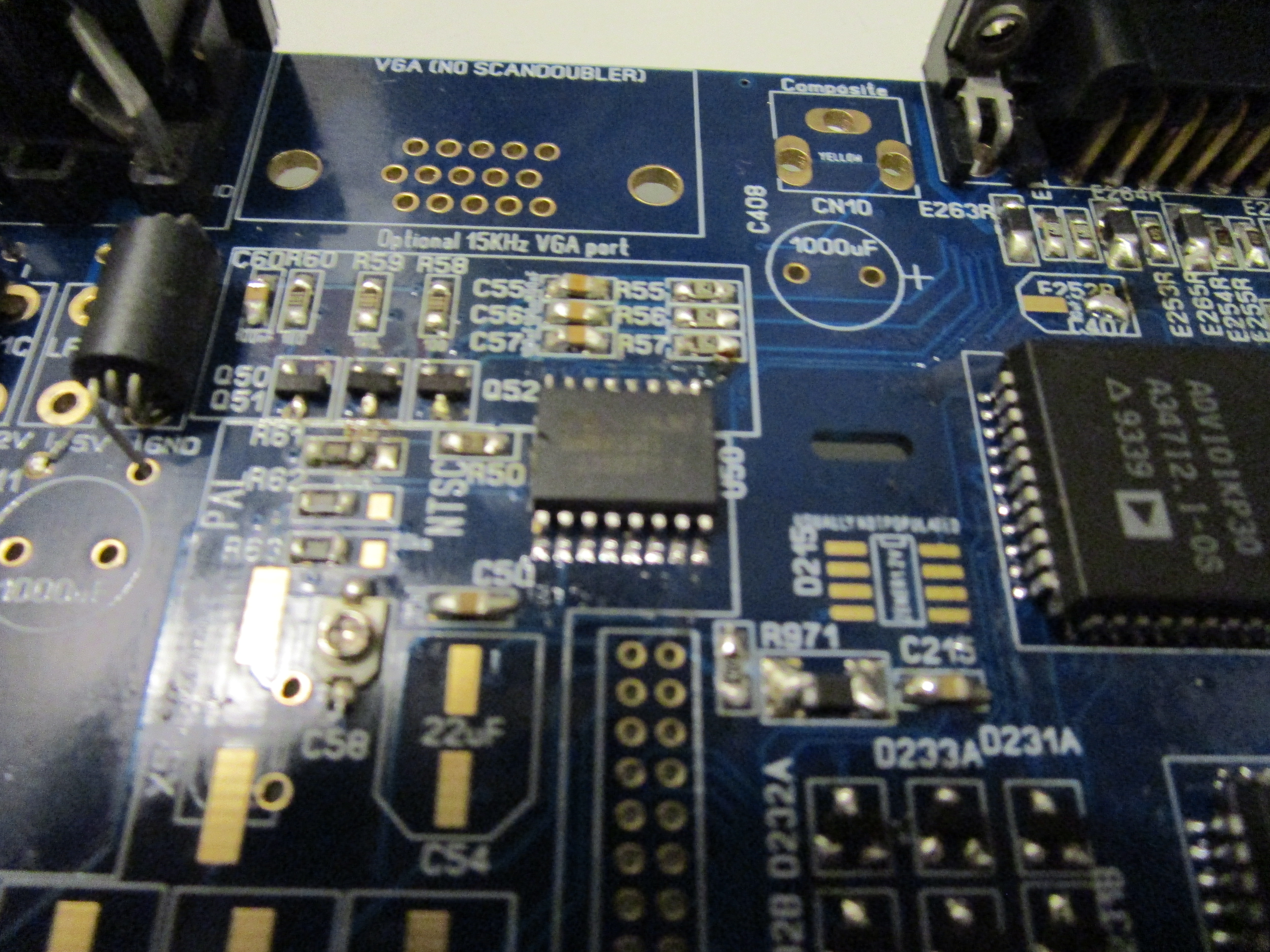

if you do not want to use VGA connector but Composite, you WILL need to add all components except the physical VGA Connector or the AD724 will not get any signals.
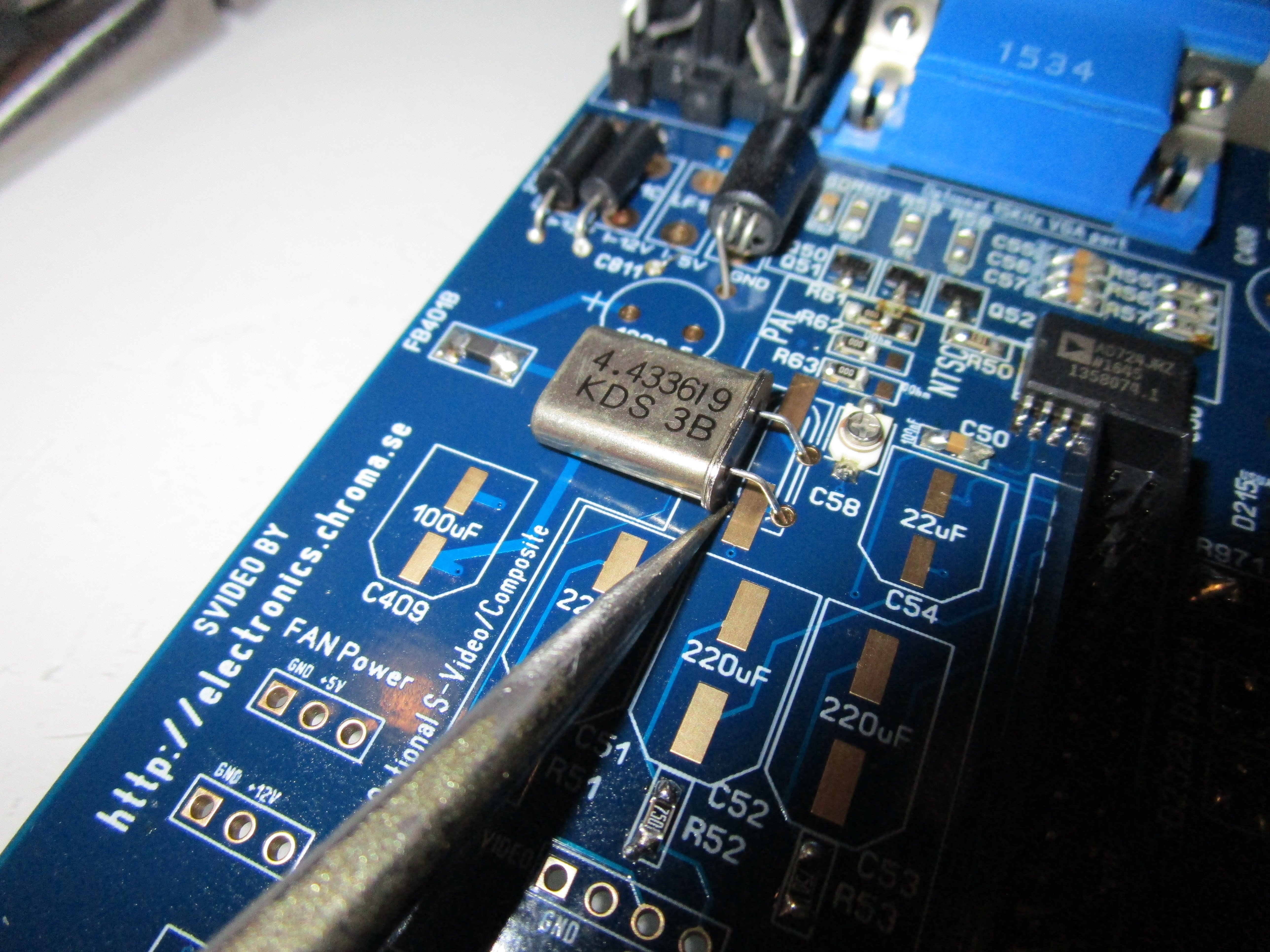
The 4.433619MHz oscillator can be soldered in as shown or you can use a SMD one. Just make sure it does NOT touch the pads for the SMD one. (this is moved from the old A1200. if you skip composite you can skip this)
The 0Ohm resistors above, when set to left like this it is set for PAL, if you want to have NTSC set to right. (the R63 resistor tells alice what mode to boot at the rest is for the composite/svideo handling)
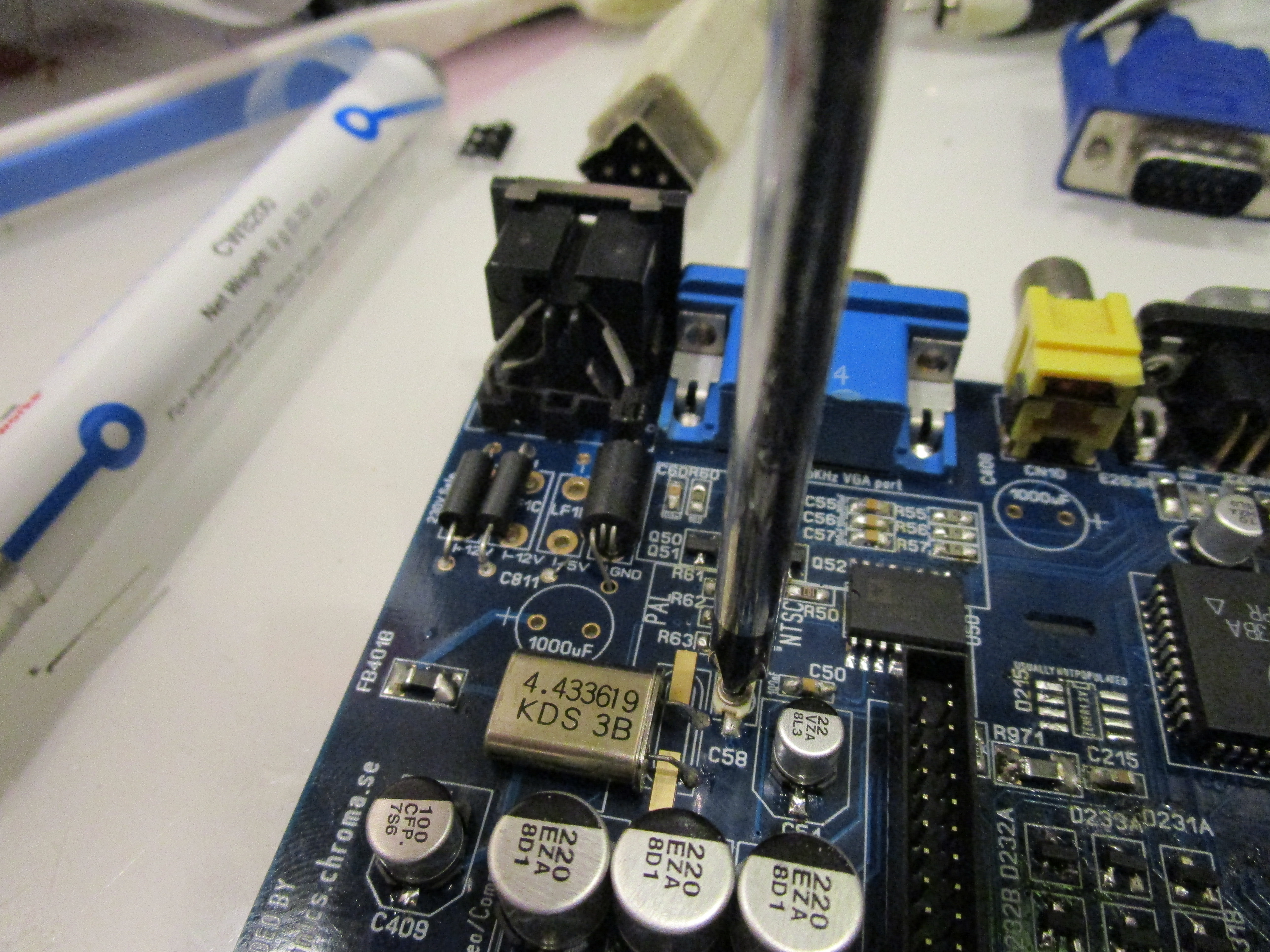
There is a variable capacitor, here you set the quality of the composite out. trim it with a plastic screwdriver if a screwdriver that is sheilded from you (or there will be interference when trimming)
do the setting using very bright colors on black background.
FAN Connectors:
on the left side there are 2 locations for fans:
here tou can see how I soldered in PC Fan-style connector. top one is 5V and bottom one is 12V. this is totally optional
And to the right:
Here you can see 2 floppy-like connectors. BPPC with BVision etc might sometimes require a lot of power so manual tells you to put in a powerconnector INTO the floppypower connector, with this you can put it into the connector closer to the CPU slot and still use floppy power as you like.. or connect a fan. it is up to you. also optional.
IRQ7 (NMI) and RESET
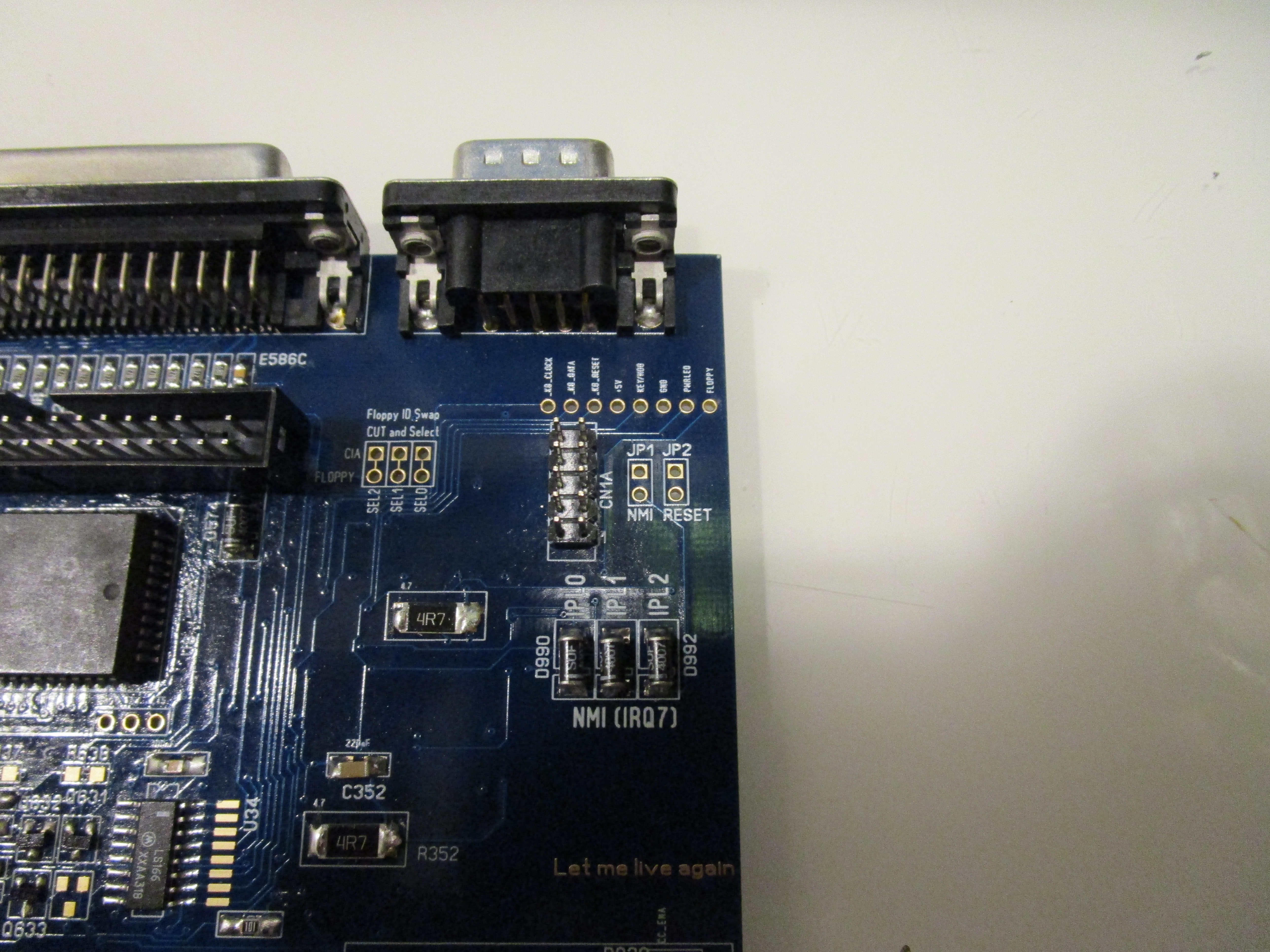
if you have soldered in the diodes for NMI. if you short the jumper for NMI (IRQ7) you will trigger a Level 7 irq. Without anything special this will just pause the machine.
but with software like HRTMon, AsmPro etc you can use it for debugging, freezing etc.
and reset.. well .. it resets the machine 🙂
and the SEL jumpers.. IF you want to use an external gotek and sometimes want it to behave like df0 while the internal drive behaves like df1. you can cut he trace (visible) and solder a connector and switch the SEL0 with SEL1 etc. for you to figure out but the top hole goes to the CIA chips and the bottom holes to the default floppy location.
Well.. thats it:
(I on this picture I have used a wire instead of the ferritecore for 5V will fix later when I find the damn thing)
Also.. if doubt this is how the floppyconnector is turned:

Remember you can test the machine witout the electrolytes.. (except audio and composite) I usually add them when the machine is working)
So.. now time for me to do that..
Enjoy your ReAmiga 1200!
Moving from a REV2B board:
If you are moving from a 2B board, first of all. you need new memorymodules.
BUT you also need to reprogram the GAL. you need to have the 1D.x code for XU9 location not the XU1 location GAL (same physical place but different name) code is in the R1200 archive.
Great work. Would like a 1.D.4 version please
I only have R1200 boards available
Could you go in a bit more detail, what equipment you use/require for this process?
Been like 30 years since I last did any soldering 🙂
For soldering I use my Hakko 888D and desoldering my hotair Atten 858D and my ZD-915 desoldingtool
Thanks for all the info. Just going through the BOM again and confused about the 2 x 1206 0 ohm resistors as they don’t seem to be listed on the locator?
Thanks
yeah I know it is.. confusing. if you check the locator it will show the 0ohm resistors for all sizes.. the 1206 ones is located at the audioports..
you can use 0805 there 🙂 actially you can use 0805 all over.
This is off-topic to this post but could you send me a personal email. I have a dead CyberStormPPC card that I’m wondering if you could take a look for possible repair.
I do not repair CSPPCs try to contact Stachu100 on Amibay
Hello Chucky,
the part EFO-MN3004A4 seems to be phased out. Mouser does not show a replacement. Can you recommend something?
thanks!
Peter
there are a few 4MHz versions that works fine aswell
Thanks alot. I’m planning to do this and already have a donor board.
Stupid question, is there anything such as SMT sockets. I hate solder irreplaceable chips.
I’m old school and everything BELONGS in a socket, but like cell phone batteries, I guess we’re stuck with components.
You can put in sockets but they are HARD to solder. 99 out of 100 times when people have issues and sockets. it is due to sockets